Table of Contents
Advertisement
OPERATION MANUAL
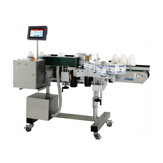
GALLON WRAP-AROUND LABELER
10861 Business Drive, Fontana, CA 92337
1.
Before operating the machine: Read thoroughly this Operating Manual to ensure the safety of the
personnel and to keep the machine in good conditions.
2.
Machine adjustment and parts changeover are only to be done by qualified and properly trained
engineers.
Model CVC 310
CVC TECHNOLOGIES, INC.
TEL: (909) 355-0311
FAX: (909) 355-0411
(ISO 9001:2000 Certified)
Advertisement
Table of Contents
Troubleshooting

Subscribe to Our Youtube Channel
Related Manuals for CVC 310

Summary of Contents for CVC 310
- Page 1 OPERATION MANUAL GALLON WRAP-AROUND LABELER Model CVC 310 CVC TECHNOLOGIES, INC. 10861 Business Drive, Fontana, CA 92337 TEL: (909) 355-0311 FAX: (909) 355-0411 (ISO 9001:2000 Certified) Before operating the machine: Read thoroughly this Operating Manual to ensure the safety of the personnel and to keep the machine in good conditions.
-
Page 2: Table Of Contents
2011.3.10 CVC TECHNOLOGIES, INC. CVC 310 OPERATION MANUAL CONTENTS ABOUT THIS MANUAL About This Manual ....................1-1 Additional Information..................1-1 SPECIFICATIONS Machine Specifications..................2-1 Label Specifications .................... 2-2 Hot Stamp Printer Specifications (Optional)............2-3 SAFETY REGULATIONS General Safety Rules ................... 3-1 Warning Signs..................... - Page 3 CVC TECHNOLOGIES, INC. CVC 310 OPERATION MANUAL Hot Stamp Printer Installation (Optional)............... 9-6 OPERATING PROCEDURE 10.1 Air Regulator Set Check (Optional) ............... 10-1 10.2 Labeler Operation ....................10-2 MACHINE SET-UP AND ADJUSTMENT 11.1 Guide Rail and Product Separator Adjustment ............11-1 11.2...
- Page 4 OPERATION MANUAL Dear Customer, Thank you for purchasing a CVC 310 Labeling Machine. We at CVC hope you will find that the Model CVC 310 meets or exceeds your expectations and requirements for an affordable, reliable and innovative addition to your packaging operation.
- Page 5 CVC 310 OPERATION MANUAL PREFACE: The Model CVC 310 is a Gallon Wrap-Around Labeler featuring CVC exclusive SelfSet control system plus a special vacuum wrap belt to assure correct placement for labels up to 18” in length. The unique design of CVC 310 SelfSet: ●...
-
Page 6: About This Manual
CVC TECHNOLOGIES, INC. CVC 310 OPERATION MANUAL ABOUT THIS MANUAL About This Manual This Operation Manual has been written by observing the CE directives, the main purpose of the regulation is in relation to the protection of personal safety and the maintenance of the machine in good conditions, as it is intended to provide the proper operation procedures to avoid causing danger and damages to persons and to the machine. -
Page 7: Specifications
10” option conveyor: 3,400 x 1,190 x 1,450 (mm) 133 ¾" x 46 ¾" x 57" Machine Weight 210 kg Noise Level * Some features or different product formats will require additional attachments and changeover parts, please consult CVC for the purchase. 2 - 1... -
Page 8: Label Specifications
CVC TECHNOLOGIES, INC. CVC 310 OPERATION MANUAL Label Specifications Backing Paper Transparent Label Height Range C: 15~150, D: 15~180, E: 15~220 (mm) Label Length Range C,D,E: 15~450 mm Label Roll Inner Diameter 38 mm & 76 mm (1 " & 3") Max. -
Page 9: Hot Stamp Printer Specifications (Optional)
CVC TECHNOLOGIES, INC. CVC 310 OPERATION MANUAL 2.2.3 Label Rolled Inside Diagram (LRI) Labels are on the inside and roll in counterclockwise (less use). Reserve a blank for hot stamp printing if needed. Counterclockwise Hot stamped code position Fig 2.2-3... - Page 10 CVC TECHNOLOGIES, INC. CVC 310 OPERATION MANUAL 2.3.1 Print Area ") Max.: 70mm (2 Fig 2.3-1 2.3.2 Type and Related Specifications Brass Type Height Type Width Narrow Line-Spacing Wide Line-Spacing Character Number Type Lines Type Type Type (Typing Max. Length) B1.3...
- Page 11 CVC TECHNOLOGIES, INC. CVC 310 OPERATION MANUAL Type Height Type Width Character Number Nickel Type Type Lines Line Spacing (Max. Length) Z1.5 1.5 mm 1.8 mm 4.7 mm (32.4 mm) Z2.0 2.0 mm 1.8 mm 4.7 mm (32.4 mm) Z2.5 2.5 mm...
- Page 12 CVC TECHNOLOGIES, INC. CVC 310 OPERATION MANUAL 2.3.3 Sample of Stamps Numbers 2.3.3.1 Brass Line-Spacing Type for Wide Head Fig 2.3-4 2.3.3.2 Brass Line-Spacing Type for Narrow Head Fig 2.3-5 2.3.3.3 Nickel Alloy Type Fig 2.3-6 2 - 6...
-
Page 13: Safety Regulations
CVC TECHNOLOGIES, INC. CVC 310 OPERATION MANUAL SAFETY REGULATIONS 3.1 General Safety Rules The safety regulations have been provided purely as a guide for the safety of all personnel involved in the operation, cleaning and maintenance of the equipment covered by this instruction manual. Please ensure that you have read and understood all safety notices before operating the equipment covered by this instruction manual, and that the recommendations here enclosed are strictly followed. - Page 14 CVC TECHNOLOGIES, INC. CVC 310 OPERATION MANUAL 3.3 Warning Sign Placements Fig 3.3-1 3 - 2...
-
Page 15: Important Safety Notices
CVC TECHNOLOGIES, INC. CVC 310 OPERATION MANUAL 3.4 Important Safety Notices Please observe the following important safety notices. Directions should be given to operating personnel ensuring the safety regulations are observed. Heed all warning signs placed on the machine by the manufacturer. - Page 16 CVC TECHNOLOGIES, INC. CVC 310 OPERATION MANUAL Be sure that the operator knows the precise location of the emergency stop button, so that it can be pressed in time upon any emergency situation. Before machine start-up, also ensure that both the Stop Button and the Emergency stop button are in “0”...
- Page 17 CVC TECHNOLOGIES, INC. CVC 310 OPERATION MANUAL It is not allowed to alter the equipment’s original appearance by alterations, maintenance or by any other means carried out on behalf of the customer/owner or by a third party. It is not allowed to place or fit any additional equipment inside any cabinet or on any part of the equipment, which are not delivered, approved or mounted by the manufacturer or sales distributor.
- Page 18 CVC TECHNOLOGIES, INC. CVC 310 OPERATION MANUAL The equipment should be serviced by qualified personnel when the equipment does not appear to operate normally or exhibits a marked change in performance. Do not attempt to clean, inspect and maintain the equipment beyond that described in this instruction manual.
- Page 19 CVC TECHNOLOGIES, INC. CVC 310 OPERATION MANUAL Setting up and troubleshooting of electrical parts must be carried out by qualified electrician or engineer. Power Box should not be opened without permission, connections made by unauthorized personnel is prohibited. During cleaning, avoid spattering water on the power box or any electric component.
-
Page 20: Installation
Have a clearance space of at least 800 mm (31½”) around the machine for operation, cleaning and maintenance purposes (refer to Fig. 4.2-1). Minimum Machine Operation Space Model Height CVC 310 (STD) 2,650 mm (104") 3,600 mm (142") 2,800 mm (110 ") Fig 4.2-1A... - Page 21 CVC TECHNOLOGIES, INC. CVC 310 OPERATION MANUAL Model Height CVC 310 2,890 mm 5,000 mm 2,800 mm (110 ") w/ 10” conveyor (option) (113 ¾") (196 ¾") Fig 4.2-1B 4 - 2...
-
Page 22: Transportation Precautions
CVC TECHNOLOGIES, INC. CVC 310 OPERATION MANUAL Transportation Precautions Remove the top cover first, and then open the 4 side panels carefully. Keep the bottom wood base for fork lift transportation. b. Check the machine and its accessories for shipping damage. -
Page 23: Transportation Procedures
CVC TECHNOLOGIES, INC. CVC 310 OPERATION MANUAL Transportation Procedures Transport the machine to the installation site with its wooden crate or wooden base safely using a 2-ton minimum fork lift. b. If the wooden base has already been removed, two people are required to hold each side of the machine to maintain balance while moving. -
Page 24: Positioning And Adjustment Of Machine Level And Height
CVC TECHNOLOGIES, INC. CVC 310 OPERATION MANUAL 4.5 Positioning and Adjustment of Machine Level and Height a. Adjust the machine to the required height and position horizontally with jacks. Place two jacks at the center position between the foot stands and under the machine aluminum base (refer to Fig. 4.5-1). -
Page 25: Installation Procedures
CVC TECHNOLOGIES, INC. CVC 310 OPERATION MANUAL INSTALLATION PROCEDURES Power Connection a. Connection of electricity supply to the machine is necessary for the operation of its electrical components. b. Connect the main power cord of the machine to the safety NFB breakers on the power source, ensuring that the voltage and amperage meet machine’s requirements. -
Page 26: U-Type Spring Clip Mounting (Optional)
CVC TECHNOLOGIES, INC. CVC 310 OPERATION MANUAL U-Type Spring Clip Mounting (Optional) Follow the illustrations given below to mount the U type spring clip before using 38mm labeling roll. It is designed to fasten the label roll when using 38mm label roll. - Page 27 CVC TECHNOLOGIES, INC. CVC 310 OPERATION MANUAL C60 Type Arrangement of the Type Holder (Optional) a. Whenever possible, it is suggested that the letter type are arranged in a centered and balanced way within the type holder area for better results. (Depend on the actual situation of the label imprinting.)
-
Page 28: Machine General Layout
CVC TECHNOLOGIES, INC. CVC 310 OPERATION MANUAL 6. MACHINE GENERAL LAYOUT Parts Identification Right Front View ○ ○ ○ ○ ○ ○ ○ ○ ○ ○ ○ ○ ○ ○ ○ ○ ○ ○ ○ ○ ○ ○ ○ ○... - Page 29 CVC TECHNOLOGIES, INC. CVC 310 OPERATION MANUAL Left Rear View ○ ○ ○ ○ ○ ○ Fig 6.1-2 6 - 2...
- Page 30 CVC TECHNOLOGIES, INC. CVC 310 OPERATION MANUAL Labeling Head Layout Fig 6.1-3 Nomenclature Nomenclature Label Roll Disk 19 Wrap Plate Height Fastening Block Rewind Spool 20 Wrap Plate Horizontal Adjustment Handwheel Label Roll Axle 21 Electrical Connector for Wrap Station...
-
Page 31: Machine Parts Functions
CVC TECHNOLOGIES, INC. CVC 310 OPERATION MANUAL Machine Parts Functions A brief description of the main components functions of the machine are given in this section, please refer to “Machine Parts Identification” section for the identification of the parts on the machine. - Page 32 CVC TECHNOLOGIES, INC. CVC 310 OPERATION MANUAL ․ No.27: "Emergency Stop Button", depress the button to stop immediately the machine operation upon emergency situations. ․ No.28: “Product Sensor”, designed to detect bottle position and bottle width. ․ No.29: "Labeling Position Height Adjustment Handwheel" provides to adjust properly the height of the labeling head.
-
Page 33: Machine Control Parts Functions
CVC TECHNOLOGIES, INC. CVC 310 OPERATION MANUAL Machine Control Parts Functions Refer to section 6.1 for the location of the different control parts. 6.3.1 Main Power Switch This main switch is used to connect or disconnect the machine from the power source, putting the switch in position “OFF”... -
Page 34: Hot Stamp Printer (Optional)
CVC TECHNOLOGIES, INC. CVC 310 OPERATION MANUAL 6.3.4 Blower Power Switch This main switch is used to connect or disconnect the blower from the power source, putting the switch in position “OFF” disconnects the power source, whereas putting it in “ON” connects the machine to the power source. -
Page 35: Pneumatic Control System
CVC TECHNOLOGIES, INC. CVC 310 OPERATION MANUAL Pneumatic Control System (Optional) Pneumatic control system is provided to control the C60 hot stamp printer if equips with this printer. 6.5.1 Air Regulating Set Responsible of regulating the compressed air connected to the machine into desired pressure. The air flowing is controlled by the air adjustment knob;... -
Page 36: General Layout And Dimensions
CVC TECHNOLOGIES, INC. CVC 310 OPERATION MANUAL General Layout and Dimensions 6.6.1 STD Labeling Machine (78 ¾”) Fig 6.6-1 6 - 9... - Page 37 CVC TECHNOLOGIES, INC. CVC 310 OPERATION MANUAL 6.6.2 10” Conveyor Labeling Machine (Option) Fig 6.6-2 6 - 10...
- Page 38 CVC TECHNOLOGIES, INC. CVC 310 OPERATION MANUAL POWER BOX Refer to the Chapter related to “Electrical Diagrams” for more detailed information regarding the functions of the electrical components. C3: Main power switch C1: Hand-Held Terminal (HHT) C5: Cooling fan C10: DC motor drive...
- Page 39 CVC TECHNOLOGIES, INC. CVC 310 OPERATION MANUAL C18: Power board C17: DC Power supply C15: Interface board C16: Transformer C4: Master board Fig 7.1-2 7 - 2...
- Page 40 CVC TECHNOLOGIES, INC. CVC 310 OPERATION MANUAL Stepper Motor Driver - Label Head JP2:Driver power DC 145V Dip Switch setting: Left: Overheating protection Spare – for future use. Left: Single Label Head stepper motor revolution switch Right: Half step motor switch: 0.9˚ revolution per signal.
- Page 41 CVC TECHNOLOGIES, INC. CVC 310 OPERATION MANUAL DC Motor Driver - Conveyor, Wrap Belt and Product Separator Wheel 5V VIN STOP U7 Power supply GND (ORG) indicator ○ VIN (BRN) Power supply indicator ○ STOP (GRN) GND (PUR) Power supply indicator ○...
- Page 42 CVC TECHNOLOGIES, INC. CVC 310 OPERATION MANUAL Note: All the LED indicators should be ON when power is ON (D11 red LED is flashing or ON). The standard operation procedures of MV are below: a. Speed adjustment: Conveyor speed: Press product speed twice, set the value at 255 (max) and then press ENTER key.
- Page 43 CVC TECHNOLOGIES, INC. CVC 310 OPERATION MANUAL DC Power Supply FG AC DC OUT Item Function AC Power Input: AC85~265V Fuse: 4A (20mm) DC 5V/12V Black Wire(BK): 12V Brown Wire(BR): 12VG Red (R) and Orange (O): 5V Yellow (Y) & Green (G): 5VG If LED D41on Interface Board is not lit as power is on, it indicates no output for switch Power (5V).
- Page 44 CVC TECHNOLOGIES, INC. CVC 310 OPERATION MANUAL Power Board a. F2 fuse is burned if transformer is short circuit. b. Check LED D37 on the interface board. If the three LED is lit, it indicates both the power board and fuse are not functional.
- Page 45 LD28 Item Lamp Function Power “ON” On “Labeling” Labeling Head “B” (for CVC 400 only) Spare – for future use Spare – for future use Spare – for future use Labeling Head “A”(for all models) Spare – for future use Spare –...
- Page 46 CVC TECHNOLOGIES, INC. CVC 310 OPERATION MANUAL Interface Board Fuse and Indicators F1 STEP B F2 STEP A F3 STEP CLAP F4 STEP H3 F5 DC 24V F6 AC IN F7 AC OUT Working Trouble Item Fuse Function Fuse Size...
-
Page 47: Special Options
CVC TECHNOLOGIES, INC. CVC 310 OPERATION MANUAL Special Options 6.7.1 10” Conveyor Labeling Machine (Reference) 10” conveyor (option) Fig 6.7-1 6 - 11... -
Page 48: Control Panel Descriptions
CVC TECHNOLOGIES, INC. CVC 310 OPERATION MANUAL HAND-HELD TERMINAL INSTRUCTION Control Panel Descriptions Fig 8.1-1 Symbol Description green Start conveyor Stop conveyor Function keys Value modification keys: decreases (-) and increases (+) Used to select different displays. Numerical keys: Used for value entry... - Page 49 CVC TECHNOLOGIES, INC. CVC 310 OPERATION MANUAL Labeling Head Switch: To turn labeling head ON or OFF, the right rectangle in the symbol becomes black to indicate that the labeling head is active. This key should also be pressed for the adjustments of LABEL DISPENSING SPEED, LABEL EXTENSION, LABEL POSITION, LABEL SENSING and LABEL LENGTH.
-
Page 50: Lcd Display Descriptions
CVC TECHNOLOGIES, INC. CVC 310 OPERATION MANUAL LCD Display Descriptions LCD-1 F1 AUTO ADJ F2 CALL F3 CURRENT MEM F1: Select this key for new products, new bottles (container) or new labels. F2: Call job setting from memory for reuse (job #1 through #50) F3: Continue with the same job as before the last power off. - Page 51 CVC TECHNOLOGIES, INC. CVC 310 OPERATION MANUAL LCD-5 F1 PD LEN F2 LA LEN F1: Product diameter measured by SelfSet F2: Label length measured by SelfSet LCD-6 F3 PRINT F3: Print Time for optional C60 Hot Stamp Printer (unit 5 m/sec), normally print time is set at 15.
-
Page 52: Selfset Tm Display Sequence
CVC TECHNOLOGIES, INC. CVC 310 OPERATION MANUAL SelfSet Display Sequence CVC 310 8 - 5... -
Page 53: Preparation Before Operation
CVC TECHNOLOGIES, INC. CVC 310 OPERATION MANUAL 9. PREPARATION BEFORE OPERATION Ensure that no foreign objects or tools are left in the machine. Ensure that air and power supply are normal. Check that there are no loose or damaged parts in the machine. - Page 54 CVC TECHNOLOGIES, INC. CVC 310 OPERATION MANUAL b. Label rolled inside (Fig 9.1-1b) (Copy Positions 5.6.7.8 of Label Position Chart, Fig 9.1-6). Fig.9.1-1b 9.1.2 Rewind Spool Tension Adjustment Use a metal clip to fasten the label web backing paper onto the rewind spool, and then manually rotate the rewind spool one rotation in the clockwise direction to ensure a proper attachment.
- Page 55 CVC TECHNOLOGIES, INC. CVC 310 OPERATION MANUAL 9.1.3 Label Advance Roller Lock and Rewind Roller Lock After installing the label roll, and then to make sure both of the label advance roller lock (1) and the rewind roller lock (2) are firmly locked (Fig 9.1-3). An improper locking will lead to an abnormal label dispensing.
- Page 56 CVC TECHNOLOGIES, INC. CVC 310 OPERATION MANUAL 9.1.5 Label Web Tightness Adjustment Always keep the label web slightly tensed is important, this ensures a smooth label dispensing and a stable label length, also avoids wrinkles or unevenness (FIG 9.1-4). Label web should lay flat on the label peel blade Correct the loose web on the peel blade.
- Page 57 CVC TECHNOLOGIES, INC. CVC 310 OPERATION MANUAL 9.1.6 Label Position Chart a. Copy Positions 1, 2, 3 and 4 are used to designate labels rolled so they are positioned on the outside of the web. b. Copy Positions 5, 6, 7 and 8 are used to designate labels rolled so they are positioned on the inside of the web.
-
Page 58: Hot Stamp Printer Installation (Optional)
CVC TECHNOLOGIES, INC. CVC 310 OPERATION MANUAL Hot Stamp Printer Installation (Optional) The hot stamp printer is an optional for the machine. The printing and labeling are accomplished synchronously; the printer must be properly adjusted and ready to operate before starting labeling. - Page 59 CVC TECHNOLOGIES, INC. CVC 310 OPERATION MANUAL the indicator is lit and stops flashing if print temperature is more than 329 ℉. The main power of the printer must be switched off to protect the heater from overheating if the indicator is lit.
-
Page 60: Air Regulator Set Check (Optional)
CVC TECHNOLOGIES, INC. CVC 310 OPERATION MANUAL 10. OPERATION INSTRUCTION a. Ensure that electric supply and compressed air are properly connected. b. Ensure that the HHT Control panel plug is properly connected to the HHT socket on the machine. c. It is necessary to adjust the working parts of the machine to a proper position according to the product to be labeled and the label to be applied. -
Page 61: Labeler Operation
CVC TECHNOLOGIES, INC. CVC 310 OPERATION MANUAL 10.2 Labeler Operation a.. Turn on the main power switch and blower power switch. b. The first identification screen is displayed as below: CVC 310 VER X.X After 3 seconds, the display is changed to:... - Page 62 CVC TECHNOLOGIES, INC. CVC 310 OPERATION MANUAL 3) Label sensitivity is set after the above two readouts display. After that, the display will change to: PLACE PRODUCT ON CONVEYOR FOR TEST 4) Place one product on the conveyor to the left of the product sensor when conveyor starts moving slowly.
- Page 63 CVC TECHNOLOGIES, INC. CVC 310 OPERATION MANUAL Press to enter the bottle diameter and then press key to confirm. Press to enter the label length, and then press key to confirm. Finally save the labeling data in memory: Press key → Job number → and then to confirm.
-
Page 64: Machine Set-Up And Adjustment
CVC TECHNOLOGIES, INC. CVC 310 OPERATION MANUAL 11. MACHINE SET-UP AND ADJUSTMENT Machine Adjustments Note: For safety and to avoid damaging to the machine, always SWITCH OFF the power before any machine adjustment. All machine adjustments should be accomplished by qualified technicians. -
Page 65: Label Head Height Adjustment
CVC TECHNOLOGIES, INC. CVC 310 OPERATION MANUAL 11.2 Label Head Height Adjustment Adjust the label head height with the head handwheel under the labeling head. Rotate the handwheel to raise or lower the labeling head. Label roll disk Label head height adj. -
Page 66: Wrap Assembly Adjustment
CVC TECHNOLOGIES, INC. CVC 310 OPERATION MANUAL 11.3 Wrap Assembly Adjustment a. Place a product between wrap plate and wrap belt, then use width adjustment handwheel of the wrap plate to adjust the width until the bottle is snugly held by the belt and the plate, but not too tight. -
Page 67: Hot Stamp Printer Adjustments (Optional)
CVC TECHNOLOGIES, INC. CVC 310 OPERATION MANUAL 11.4 Hot Stamp Printer Adjustments C60 Hot Stamp Printer is an optional item for the machine. It is used for coding and dating on the labels. Printing action must be synchronized with labeling action. Proper adjustment is required before starting the machine. - Page 68 CVC TECHNOLOGIES, INC. CVC 310 OPERATION MANUAL 11.5.3 Label Dispense Speed (LAB SPD) Adjustment Generally, this parameter is automatically synchronized with wrap station by SelfSet , and no adjustments are necessary. Only the following two situations, the adjustments are required: a.
- Page 69 CVC TECHNOLOGIES, INC. CVC 310 OPERATION MANUAL The label should be pulled a little tight by The backing paper should be the advancing product while performing stretched out on the label peel blade wrapping job while performing dispensing job Fig 11.5-3 11.5.4...
- Page 70 CVC TECHNOLOGIES, INC. CVC 310 OPERATION MANUAL 11.5.5 Labeling Position (POSITN) Adjustment a. SelfSet will automatically calculate the correct label position and no adjustment is required. Only slight adjustment is necessary to carry out for some special cases. Check and verify the label position is within standard range before performing the labeling (Fig 11.5-5).
- Page 71 CVC TECHNOLOGIES, INC. CVC 310 OPERATION MANUAL 11.5.6 Labeling Sensitivity (LAB SENS) Adjustment a. Label sensor indicates the sensitivity of the backing paper translucency or opacity; the sensitivity of the label sensor can be adjusted. b. Owing to the different product applied, the label thickness, label material and the opacity of labels are also different.
- Page 72 CVC TECHNOLOGIES, INC. CVC 310 OPERATION MANUAL f. Two or more labels dispensing may also be caused by an incorrect detecting point of the label sensor to label (e.g. If the sensor detecting point is positioned on the label edge as shown in Fig. A &...
-
Page 73: Product Sensor Adjustments
CVC TECHNOLOGIES, INC. CVC 310 OPERATION MANUAL 11.6 Product Sensor Adjustments The function of product sensor (WL-4G) is to detect bottle width (a tolerance of 1-2mm showed on the LCD display is possible and acceptable), and then sends the signal of bottle width to SelfSet to perform labeling job. -
Page 74: Clear Label Sensor Adjustment Procedures (Optional)
CVC TECHNOLOGIES, INC. CVC 310 OPERATION MANUAL 11.7 Clear Label Sensor Adjustment Procedures (Optional) a. Thread the labels around the rollers and thru the label sensor as described by the manual. b. Remove a label from under the label sensor. -
Page 75: Rewind Spool Tension Adjustments
CVC TECHNOLOGIES, INC. CVC 310 OPERATION MANUAL LABEL LABEL LABEL LABEL SPAN SPAN SHIFT SHIFT Fig.11.7-1 11.8 Rewind Spool Tension Adjustments If the web is loose during operation, it is necessary to increase the rewind spool tension with the adjustment knob (Fig 11.8-1). -
Page 76: Missing Date Code Sensor Adjustments (Optional)
CVC TECHNOLOGIES, INC. CVC 310 OPERATION MANUAL 11.9 Missing Date Code Sensor Adjustments (Optional) Missing Date Code Sensor module (optional) (SICK, KT5W-2N1116) Fig.11.9-1 The Date Code Sensor is provided for detecting the unqualified label-imprinting. If the label is not imprinted and detected by the sensor, the LCD display will show the warning message and the machine will stop. -
Page 77: Wrap Station Changeover (Optional)
CVC TECHNOLOGIES, INC. CVC 310 OPERATION MANUAL 11.10 Wrap Station Changeover (Optional) The changeover components and procedures of the wrap station are illustrated as follows: Step 1. Install the wrap plate. Step 2. Step 3. Fasten the screws. Fasten the lever. - Page 78 CVC TECHNOLOGIES, INC. CVC 310 OPERATION MANUAL Step 4. Install the wrap belt assembly. Step 5. Step 6. Ensure the mechanism matches the gear Equip the vacuum pipe. wheel. 11 - 15...
- Page 79 CVC TECHNOLOGIES, INC. CVC 310 OPERATION MANUAL Step 7. Fasten the screw. Step 8. Ensure the wrap belt assembly is properly installed, and then do a final adjustment according to the size and height of the product. 11 - 16...
-
Page 80: Complementary Tools
CVC TECHNOLOGIES, INC. CVC 310 OPERATION MANUAL COMPLEMENTARY TOOLS 12.1 Complementary Tools Note: Tool set may differ when machine is sold as part of an integrated line. 12.1.1 Tool Box A tool box is provided with the shipment, containing some useful tools (Fig 12.1-1). - Page 81 CVC TECHNOLOGIES, INC. CVC 310 OPERATION MANUAL 12.1.3 U-Type Spring Clip (Optional) This clip is designed for fastening 38 mm Labeling roll (Fig 12.1-3). Fig 12.1-3 12 - 2...
-
Page 82: Maintenance
CVC TECHNOLOGIES, INC. CVC 310 OPERATION MANUAL 13. MAINTENANCE 13.1 General Precautions a. Safety ․Before performing any maintenance job or cleanup, ensure that the power is disconnected. ․Always take the necessary safety measures to protect both machine and personnel when carrying out maintenance job b. -
Page 83: Air Regulator Set Maintenance (Optional)
CVC TECHNOLOGIES, INC. CVC 310 OPERATION MANUAL 13.3 Air Regulator Set Maintenance (Optional for C60 Hot Stamp Printer) The air regulator is equipped with an air filter; drain the accumulated water of the reservoir and check after every usage. Inspect and ensure the lubrication oil reservoir is sufficient. -
Page 84: Maintenance And Lubrication Schedule
CVC TECHNOLOGIES, INC. CVC 310 OPERATION MANUAL 13.4 Maintenance and Lubrication Schedule Machine parts Maintenance Period Remarks Labeling head height Lubrication Weekly Wipe out old grease and adj. screw (ISO VG 32) apply new grease. Wrap belt height adj. Lubrication... - Page 85 CVC TECHNOLOGIES, INC. CVC 310 OPERATION MANUAL 14. ELECTRICAL AND PNEUMATIC DIAGRAMS 14 - 1...
-
Page 86: Pin Descriptions
CVC TECHNOLOGIES, INC. CVC 310 OPERATION MANUAL 14.1 Pin Description 14.1.1 Side-Plate (Power Box) Labeling Head A (Right, X2) ※ Stepper Motor Coil Labeling Head A (Right, X2) Pin No. Color Definition Pin No. Color Definition Pin No. Color Definition A’... - Page 87 CVC TECHNOLOGIES, INC. CVC 310 OPERATION MANUAL Digital I/O Pin No. Color Definition Pin No. Color Definition Pin No. Color Definition DC 12 V Encoder, Conveyor encoder Backlog sensor, BLK Product sensor PH B Product sensor, (310) Positioning sensor DC 12 V...
- Page 88 CVC TECHNOLOGIES, INC. CVC 310 OPERATION MANUAL 14.1.2 Wiring Duct ※ The input components should be matched with DC 12VG, and the output components should be matched with DC 24V or DC 12V (depending on the voltage of the component applied, motor is excluded) Stepper Motor Coil Labeling Head A (Right, X2) <4P>...
- Page 89 CVC TECHNOLOGIES, INC. CVC 310 OPERATION MANUAL Digital Sensor Product Sensor <3P> Positioning Sensor <3P> (optional) Pin No. Color Jump No. Definition Pin No. Color Jump No. Definition J31-1 DC 12V J31-1 DC 12V, Positioning solenoid J31-4 DC 12VG J31-4...
- Page 90 CVC TECHNOLOGIES, INC. CVC 310 OPERATION MANUAL 14.2 Pneumatic Diagram for C60 Hot Stamp Printer 14 - 6...
- Page 91 CVC TECHNOLOGIES, INC. CVC 310 OPERATION MANUAL 14.3 Wiring Diagrams 14.3.1 Labeler 14 - 7...
- Page 92 CVC TECHNOLOGIES, INC. CVC 310 OPERATION MANUAL Labeler Machine Wiring Diagram (A) STEP FUSE CLAP STEP FUSE CLAP STEP FUSE CLAP STEP FUSE FUSE POWER BOARD AC 110V FUSE 34 BUS FUSE 40 BUS FUSE TRANSFORMER conveyor wrap around separator...
- Page 93 CVC TECHNOLOGIES, INC. CVC 310 OPERATION MANUAL Labeler Machine Wiring Diagram (B) 14 - 9...
- Page 94 CVC TECHNOLOGIES, INC. CVC 310 OPERATION MANUAL 14.3.2 C60 Hot Stamp Printer (Optional) 14 - 10...
- Page 95 CVC_F26_001 CVC TECHNOLOGIES, INC. No.361, Renhua Rd. Dali City, Taichung County, Taiwan Phone. 886-4-24969922 Company / customer Job number E06001C Project description Manufacturer (company) CVC TECHNOLOGIES, INC. Path Project name E06001 make Type Place of installation +MP1 Power supply 1Φ110 V AC...
- Page 96 S1000997 =E060+MP1/01.4:D Electric Valve SY5120-5G-01 S8000091 =E060+MP1-01Y1 Solenoid valve =E060+MP1/01.3:D =E060+MP1-PLT-168P Connector Connector PLT-168P S1000227 =E060+MP1/01.2:B E06001C Date 2010/10/4 REPORT Drawn 20020401 PARTSLIST Parts list : S1000537 - S1000227 Designed Page E06001C CVC TECHNOLOGIES,INC Modification Date Name Next =E060+BM/01 Approved...
- Page 97 -01E1 -01B1 -01S1 -01F1 -01S3 -01Y1 -01S2 -01U1 -PLT-168P E06001C Date 2010/10/7 E060 Drawn 20020401 Parts Figure Designed Designed Page E06001C CVC TECHNOLOGIES,INC Modification Date Name Next +MP1/01 Approved...
- Page 98 -01W1 -01U1 -01S2 -01S3 -01X1 -01F1 -01S1 -01Y1 -01V1 -01E1 -01B1 Electric Valve Ribbon Sensor Temperature Heater Thermocouple (Option) Controller E06001C Date 2010/10/7 E060 Drawn 20020401 Power circuitry Designed Designed Page E06001C CVC TECHNOLOGIES,INC Modification Date Name Approved Next Approved...
- Page 99 CVC_F26_001 CVC TECHNOLOGIES, INC. No.361, Renhua Rd. Dali City, Taichung County, Taiwan Phone. 886-4-24969922 Company / customer Job number E06002C Project description Manufacturer (company) CVC TECHNOLOGIES, INC. Path Project name E06002 make Type Place of installation +MP1 Power supply 1Φ110 V AC...
- Page 100 Solenoid valve =E060+MP1/01.3:D =E060+MP1-01Y2 Solenoid valve 525158 MHP3-M1H-3/2O-1/8 FESTO S8000681 =E060+MP1/01.3:D Connector PLT-168P S1000227 =E060+MP1-PLT-168P Connector =E060+MP1/01.2:B E06002C Date 2010/10/4 REPORT Drawn 20020401 PARTSLIST Parts list : S1000537 - S1000227 Designed Page E06002C CVC TECHNOLOGIES,INC Modification Date Name Next =E060+BM/01 Approved...
- Page 101 -01E1 -01B1 -01S1 -01F1 -01Y1 -01S3 -01S2 -01Y1 -01U1 -PLT-168P E06002C Date 2010/10/7 E060 Drawn 20020401 Parts Figure Designed Designed Page E06002C CVC TECHNOLOGIES,INC Modification Date Name Next +MP1/01 Approved...
- Page 102 -01U1 -01S2 -01S3 -01X1 -01F1 -01Y2 -01V1 -01Y1 -01S1 -01E1 -01B1 Electric Valve Ribbon Sensor Temperature Heater Thermocouple (Option) Controller E06002C Date 2010/10/4 E060 Drawn 20020401 Power circuitry Designed Designed Page E06002C CVC TECHNOLOGIES,INC Modification Date Name Approved Next Approved...
-
Page 103: Spare Parts List
CVC TECHNOLOGIES, INC. CVC 310 OPERATION MANUAL 15. SPARE PARTS LIST 15.1 Labeling Machine Part Number Reference Descriptions Number Product sensor (SICK): WL4G-3N1382P01 Standard, new type S1000407 WL4G-2 Standard, old type WL9-2N Special type for transparent container Label sensor: W0090067 LABEL-7P a. -
Page 104: C60 Hot Stamp Printer (Optional)
Hot stamp silicone pad (50H02010) S1000537 KBSGN-43H05 Thermal IC S8000091 SY5120 Solenoid valve S1000491 110V – 60W Heater *This part must be procured only from CVC to avoid any damage to the printer. 50H06000 50H06000 Air cylinder 15 - 2... -
Page 105: Electrical Parts List
CVC TECHNOLOGIES, INC. CVC 310 OPERATION MANUAL 15.3 Electrical Parts List Reference Item Part Number Description Specification Remark Number TO-2-1 S1000921 Main Power Switch S1000792 Main Board S1000791 Interface Board PWR5 S1000925 Power Board DCMD-8 S1000789 DC Motor Drive DC Motor Drive, Wrap... - Page 106 CVC TECHNOLOGIES, INC. CVC 310 OPERATION MANUAL 42A78BEPM-F3 S1000775 10” conveyor motor 1/3hP (40:1) Bodine (4193) (option) HES-036-2MHC S1000393 Attach w/ optional 10” ROTARY conveyor 15 - 4...
-
Page 107: Troubleshooting
CVC TECHNOLOGIES, INC. CVC 310 OPERATION MANUAL 16. TROUBLESHOOTING 16.1 Troubleshooting for Labeling Problem Possible Cause Suggested Solution 1. Label partially dispensed so that the a. Improper adjustment of label sensor a. Remove the label in front of label backing paper is pulled by container. - Page 108 CVC TECHNOLOGIES, INC. CVC 310 OPERATION MANUAL 4. Dispensing two labels at a time a. The sensitivity value of the label is a. Increase label sensitivity value. too close to the value of the backing paper. It is unable to send out signal to stop it.
-
Page 109: Troubleshooting For C60 Hot Stamp Printer (Optional)
CVC TECHNOLOGIES, INC. CVC 310 OPERATION MANUAL 16.2 Troubleshooting for C60 Hot Stamp Printer Problem Possible Cause Suggested Solution 1. Heater indicator light remains Heater is not functioning. Replace the heater. orange, dose not turn to green 2. Thermal indicator light remains Thermal IC is not functioning. -
Page 110: Error Message
CVC TECHNOLOGIES, INC. CVC 310 OPERATION MANUAL 16.3 Error Message a. Product sensor error: PRODUCT SENSOR ERR Problem: Product sensor is malfunctioned or product is abnormal. PLEASE CHECK After solving the problem, press START PRESS ‘START’ KEY 5 SEC. RESTART key for 5 seconds to restart the machine. -
Page 111: Appendix
CVC TECHNOLOGIES, INC. CVC 310 OPERATION MANUAL 17. APPENDIX 17 - 1... - Page 112 CVC TECHNOLOGIES, INC. CVC 310 OPERATION MANUAL 32A5BEPM-W3 (Bodine) for Wrap Station 17 - 2...
- Page 113 CVC TECHNOLOGIES, INC. CVC 310 OPERATION MANUAL 42A5BEPM-E3C4183 (Bodine) for Conveyor 17 - 3...
- Page 114 CVC TECHNOLOGIES, INC. CVC 310 OPERATION MANUAL Clear Label Sensor (LRD 6110) 17 - 4...
- Page 115 CVC TECHNOLOGIES, INC. CVC 310 OPERATION MANUAL 17 - 5...
- Page 116 CVC TECHNOLOGIES, INC. CVC 310 OPERATION MANUAL 17 - 6...
- Page 117 CVC TECHNOLOGIES, INC. CVC 310 OPERATION MANUAL 17 - 7...
- Page 118 CVC TECHNOLOGIES, INC. CVC 310 OPERATION MANUAL 17 - 8...
- Page 119 CVC TECHNOLOGIES, INC. CVC 310 OPERATION MANUAL 17 - 9...
- Page 120 CVC TECHNOLOGIES, INC. CVC 310 OPERATION MANUAL 17 - 10...
- Page 121 CVC TECHNOLOGIES, INC. CVC 310 OPERATION MANUAL 17 - 11...
- Page 122 CVC TECHNOLOGIES, INC. CVC 310 OPERATION MANUAL 17 - 12...
- Page 123 CVC TECHNOLOGIES, INC. CVC 310 OPERATION MANUAL 17 - 13...
- Page 124 CVC TECHNOLOGIES, INC. CVC 310 OPERATION MANUAL 17 - 14...
- Page 125 CVC TECHNOLOGIES, INC. CVC 310 OPERATION MANUAL 17 - 15...
- Page 126 CVC TECHNOLOGIES, INC. CVC 310 OPERATION MANUAL 17 - 16...
- Page 127 CVC TECHNOLOGIES, INC. CVC 310 OPERATION MANUAL 17 - 17...
- Page 128 CVC TECHNOLOGIES, INC. CVC 310 OPERATION MANUAL 17 - 18...
Need help?
Do you have a question about the 310 and is the answer not in the manual?
Questions and answers