Advertisement
Quick Links
Advertisement

Related Manuals for AUMA LE Series

Summary of Contents for AUMA LE Series
- Page 1 Linear thrust unit LE 12.1 LE 200.1 Operation instructions Assembly, operation, commissioning...
- Page 2 LE 12.1 LE 200.1 Table of contents Read operation instructions first. Observe safety instructions. These operation instructions are part of the product. Retain operation instructions during product life. Pass on instructions to any subsequent user or owner of the product. Purpose of the document: This document contains information for installation, commissioning, operation and maintenance staff.
- Page 3 LE 12.1 LE 200.1 Table of contents Certificates..........................9.1. EU Declaration of Conformity / Declaration of Incorporation Index............................Addresses..........................
- Page 4 Any device modification requires prior written consent of the manufacturer. 1.2. Range of application AUMA linear thrust units are designed for the operation of industrial valves, e.g. globe valves. Other applications require explicit (written) confirmation by the manufacturer. The following applications are not permitted, e.g.:...
- Page 5 LE 12.1 LE 200.1 Safety instructions Lifting appliances according to EN 14502 Passenger lifts according to DIN 15306 and 15309 Service lifts according to EN 81-1/A1 Escalators Continuous duty Radiation exposed areas in nuclear power plants No liability can be assumed for inappropriate or unintended use. Observance of these operation instructions is considered as part of the device's designated use.
- Page 6 LE 12.1 LE 200.1 Identification Identification 2.1. Name plate Figure 1: Arrangement of name plates Linear thrust unit name plate Additional plate, e.g. KKS (Power Plant Classification System) plate or approval plate Description of linear thrust unit name plate Figure 2: Linear thrust unit name plate (example) Name of manufacturer Address of manufacturer Type and size (see explanation below)
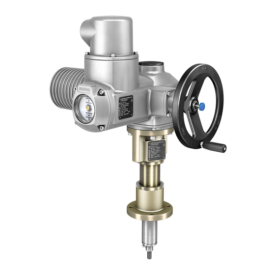
- Page 7 They are used in combination with multi-turn actuators on valves which require linear travel. The linear thrust units convert the output torque of the multi-turn actuator into an axial thrust. As an option, AUMA linear thrust units are available with spring-loaded damping devices to compensate for changes in lengths caused by varying...
- Page 8 LE 12.1 LE 200.1 Transport, storage and packaging Transport, storage and packaging 3.1. Transport For transport to place of installation, use sturdy packaging. Hovering load! Death or serious injury possible. Do NOT stand below hovering load. Linear thrust units mounted to a valve in combination with an actuator: Attach ropes or hooks for the purpose of lifting by hoist to valve and NOT to actuator.
- Page 9 LE 12.1 LE 200.1 Transport, storage and packaging Weights linear thrust units Type Stroke Weight [kg] Base weight [kg] LE 70.1 / LE 100.1 LE 200.1 Refer to name plate Without actuator and base 3.2. Storage Danger of corrosion due to inappropriate storage! Store in a well-ventilated, dry room (maximum humidity 70 %).
- Page 10 State of delivery When AUMA actuators and linear thrust units up to size LE 50.1 and a stroke of max. 200 mm are supplied together, assembly is performed in the factory. For larger strokes and when exceeding size LE 70.1, assembly must be performed by the customer.
- Page 11 LE 12.1 LE 200.1 Assembly Suitable AUMA actuators, flanges, and screws Type Suitable AUMA actuator Actuator mounting flange Screws Tightening torque T [Nm] EN ISO 5210 Size Quantity Strength class A2-70 LE 70.1 SA 14.2/SAR 14.2 F14, F14-ZB M16 x 40 LE 100.1...
- Page 12 LE 12.1 LE 200.1 Assembly Attachment dimensions to valve Dimensions LE 12.1 LE 25.1 LE 50.1 LE 70.1 LE 100.1 LE 200.1 EN ISO 5210 (DIN 3210) (G0) (G0) (G0) (G0) (G1/2) (G1/2) (G3) ∅ d6 g7 ∅ d8 M12 x 1.25 M16 x 1.5 M20 x 1.5 M36 x 3...
- Page 13 5.2. Thrust limitation Thrust limitation is made via mounted actuator. Refer to <Limit switching: set> chapter in operation instructions of suitable AUMA multi-turn actuators. Damage at linear thrust unit due to excessive torque! Max. permissible thrusts may not be exceeded.
- Page 14 Danger of jamming. Keep hands clear from stroke range of combination. If necessary, fit protection cover. Information: AUMA linear thrust units type LE 12.1 LE 200.1 leave the factory Verify stroke direction with retracted stem (end position OPEN). Move actuator manually to intermediate position or to sufficient distance from end position.
- Page 15 Therefore, we recommend contacting our service. Only perform servicing and maintenance tasks when the device is switched off. AUMA AUMA offers extensive service such as servicing and maintenance as well as Service & Support customer product training. For the relevant contact addresses, please refer to <Addresses>...
- Page 16 LE 12.1 LE 200.1 Servicing and maintenance 6.3. Re-lubrication Re-lubrication is only necessary if grease has been visibly leaking and can be performed through the grease nipple while mounted. Figure 6: Grease nipple and vent Stem Hexagonal screw for venting Grease nipple Move stem [1] to upper position (retracted).
- Page 17 Information on the customer-specific version, refer to the order-related data sheet. The technical data sheet can be downloaded from the Internet in both German and English at ht- tp://www.auma.com (please state the order number). 7.1. Features and functions Features and functions...
- Page 18 The tests to ensure conformity with ATEX directive 2014/34/EU were performed according to the technical data. For other applications, please consult AUMA. 100 % load may only be applied for a short time during opening and closing. Sufficient pause times have to be respected.
- Page 19 LE 12.1 LE 200.1 Spare parts Spare parts 8.1. Linear thrust unit LE 12.1 LE 200.1...
- Page 20 Spare parts Please state device type and our order number (see name plate) when ordering spare parts. Only original AUMA spare parts should be used. Failure to use original spare parts voids the warranty and exempts AUMA from any liability. Representation of spare parts may slightly vary from actual delivery.
- Page 21 LE 12.1 LE 200.1 Spare parts 8.2. Linear thrust units LE 12.1 — LE 200.1 with base...
- Page 22 Spare parts Please state device type and our order number (see name plate) when ordering spare parts. Only original AUMA spare parts should be used. Failure to use original spare parts voids the warranty and exempts AUMA from any liability. Representation of spare parts may slightly vary from actual delivery.
- Page 23 Certificates are valid as from the indicated date of issue. Subject to changes without Information notice. The latest versions are attached to the device upon delivery and also available for download at http://www.auma.com. 9.1. EU Declaration of Conformity / Declaration of Incorporation...
- Page 24 LE 12.1 LE 200.1 Index Index Safety instructions Safety instructions/warnings Screws Actuator mounting flange Self-locking Actuators Serial number Ambient temperature 6, 18 Service Applications Service conditions Approval plate Servicing Assembly Size Attachment dimensions Spare parts Standards Stem Certificates Storage Commissioning 4, 13 Stroke Corrosion protection...
- Page 25 AUMA Finland Oy AUMA Polska Sp. z o.o. FI 02230 Espoo PL 41-219 Sosnowiec Tel +358 9 5840 22 Tel +48 32 783 52 00 AUMA Riester GmbH & Co. KG auma@auma.fi biuro@auma.com.pl www.auma.fi www.auma.com.pl Location Muellheim DE 79373 Muellheim AUMA France S.A.R.L.
- Page 26 AUMA worldwide AUMA South Africa (Pty) Ltd. Mikuni (B) Sdn. Bhd. Mustafa Sultan Science & Industry Co LLC ZA 1560 Springs BN KA1189 Kuala Belait OM Ruwi Tel +27 11 3632880 Tel + 673 3331269 / 3331272 Tel +968 24 636036 aumasa@mweb.co.za...
- Page 27 AUMA worldwide...
- Page 28 AUMA Riester GmbH & Co. KG P.O. Box 1362 DE 79373 Muellheim Tel +49 7631 809 - 0 Fax +49 7631 809 - 1250 info@auma.com www.auma.com Y000.346/003/en/1.20 For detailed information on AUMA products, refer to the Internet: www.auma.com...
Need help?
Do you have a question about the LE Series and is the answer not in the manual?
Questions and answers