Table of Contents
Advertisement
Quick Links
Advertisement
Table of Contents

Related Manuals for Zurich ZR15

Summary of Contents for Zurich ZR15
- Page 2 Table of Contents SAFETY PRECAUTIONS IMPORTANT SAFETY INFORMATION .......... SCAN TOOL CONTROLS CONTROLS AND INDICATORS ............. DISPLAY FUNCTIONS ..............BATTERY REPLACEMENT ............. USING THE SCAN TOOL CODE RETRIEVAL PROCEDURE ..........THE SYSTEM MENU ................ VIEWING OEM ENHANCED DTCs (except Ford/Mazda) ....VIEWING OEM ENHANCED DTCs (Ford/Mazda only) ....
- Page 3 Safety Precautions IMPORTANT SAFETY INFORMATION IMPORTANT SAFETY INFORMATION Read all safety warnings and all instructions. Failure to follow the warnings and instructions may result in electric shock, fire and/or serious injury. Save all warnings and instructions for future reference. 1. Operating a vehicle indoors CAN KILL YOU IN MINUTES. Engine exhaust contains carbon monoxide.
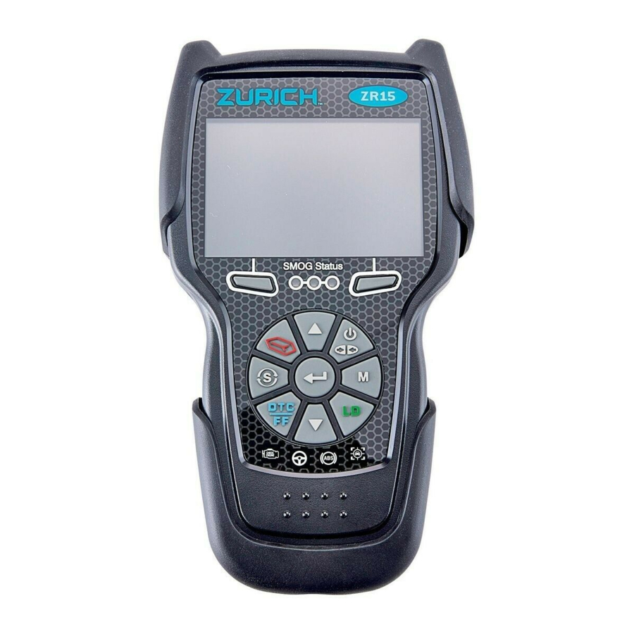
- Page 4 Scan Tool Controls CONTROLS AND INDICATORS CONTROLS AND INDICATORS Figure 1. Controls and Indicators See Figure 1 for the locations of items 1 through 16, below. ERASE button - Erases Diagnostic Trouble Codes (DTCs), and “Freeze Frame” data from the vehicle’s computer, and resets Monitor status.
- Page 5 Scan Tool Controls DISPLAY FUNCTIONS DOWN button - When in MENU mode, scrolls DOWN through the menu options. When LINKED to a vehicle, scrolls DOWN through the current display screen to display additional data. 10. Left Option Button - Selects the associated option shown on the display (Yes/No, Previous/Next, etc).
- Page 6 Scan Tool Controls DISPLAY FUNCTIONS 2. Monitor icons - Indicate which Monitors are supported by the vehicle under test, and whether or not the associated Monitor has run its diagnostic testing (Monitor status). A solid green icon indicates the associated Monitor has completed its diagnostic testing. A flashing red icon indicates that the vehicle supports the associated Monitor, but the Monitor has not yet run its diagnostic testing.
- Page 7 Scan Tool Controls BATTERY REPLACEMENT BATTERY REPLACEMENT Replace batteries when the battery symbol is visible on display and/or the 3 LEDS are all lit and no other data is visible on screen. 1. Locate the battery cover on the back of the Scan Tool. 2.
- Page 8 Using the Scan Tool CODE RETRIEVAL PROCEDURE CODE RETRIEVAL PROCEDURE Retrieving and using Diagnostic Trouble Codes (DTCs) for troubleshooting vehicle operation is only one part of an overall diagnostic strategy. Never replace a part based only on the DTC definition. Each DTC has a set of testing procedures, instructions and flow charts that must be followed to confirm the location of the problem.
- Page 9 Using the Scan Tool CODE RETRIEVAL PROCEDURE A PROTOCOL is a set of rules and procedures for regulating data transmission between computers, between testing equipment and computers. As of this writing, five different types of protocols (ISO 9141, Keyword 2000, J1850 PWM, J1850 VPW and CAN) are in use by vehicle manufacturers.
- Page 10 Using the Scan Tool CODE RETRIEVAL PROCEDURE 9. When New Vehicle is chosen from the Select Vehicle screen, the Select Year screen displays. Select the desired vehicle model year, then press ENTER The Select Make screen displays. Select the desired vehicle make, then press ENTER The Select Model screen displays.
- Page 11 Using the Scan Tool CODE RETRIEVAL PROCEDURE If a recommended solution for the “priority” DTC is not available, an advisory message displays. Press DTC/FF to scroll to the next DTC. In the case of long code definitions, a small arrow is shown in the upper/lower right-hand corner of the display area to indicate the presence of additional information.
- Page 12 Using the Scan Tool CODE RETRIEVAL PROCEDURE Choose FixAssist to view FixAssist information for the “priority” DTC. Choose Freeze Frame to view Freeze Frame data for the “priority” DTC. DTC’s that start with “P0”, “P2” and some “P3” are considered Generic (Universal).
- Page 13 Using the Scan Tool THE SYSTEM MENU / VIEWING OEM ENHANCED DTCs (except Ford/Mazda) To prolong battery life, the Scan Tool automatically shuts “Off” approximately three minutes after it is disconnected from the vehicle. The DTCs retrieved, Monitor Status and Freeze Frame data (if any) will remain in the Scan Tool’s memory, and may be viewed at any time by turning the unit “On”.
- Page 14 Using the Scan Tool VIEWING OEM ENHANCED DTCs (Ford/Mazda only) If the Scan Tool cannot link to the vehicle’s computer after three attempts, the message “Contact Technical Support” displays. - Choose System Menu to return to the System Menu. - Turn the ignition off, and disconnect the Scan Tool. - Contact Technical Support for assistance.
- Page 15 Using the Scan Tool VIEWING OEM ENHANCED DTCs (Ford/Mazda only) If KOER is selected, an advisory message shows. - Start and warm the engine to normal operating temperature, then choose Continue. Proceed to step 3. 2. If KOEO or Continuous Memory is selected, an “instructional” message shows.
- Page 16 Using the Scan Tool VIEWING ABS DTCs I/M MONITOR STATUS icons are not displayed when viewing enhanced DTCs. In the case of long code definitions, a small arrow is shown in the upper/ lower right-hand corner of the code display area indicate the presence of additional information.
- Page 17 Using the Scan Tool VIEWING SRS DTCs - Choose Relink to try again, or, choose System Menu to return to the System Menu. If the Scan Tool cannot link to the vehicle’s computer after three attempts, the message “Contact Technical Support” displays. - Choose System Menu to return to the System Menu.
- Page 18 Using the Scan Tool NETWORK TEST If the Scan Tool fails to link to the vehicle’s computer, a "Communication Error" message shows. - Ensure your vehicle is OBD2 compliant. - Verify the connection at the DLC, and verify the ignition is ON. - Turn the ignition OFF, wait 5 seconds, then back ON to reset the computer.
- Page 19 Using the Scan Tool NETWORK TEST To scan all modules: 1. Select Scan All Modules from the System Menu, then press ENTER A “One moment please” message displays while the Scan Tool scans all available modules. When the scan is complete, the Available Systems screen displays.
- Page 20 Using the Scan Tool NETWORK TEST 4. If more than one code was retrieved press DTC/FF to display additional codes one at a time. Whenever the Scroll function is used, the Scan Tool’s communication link with the vehicle’s computer disconnects. To re-establish communication, press POWER/LINK again.
- Page 21 Using the Scan Tool ERASING DIAGNOSTIC TROUBLE CODES (DTCs) If the definition for the currently displayed code is not available, an advisory message shows. I/M MONITOR STATUS icons are not displayed when using the Network Test function. In the case of long code definitions, a small arrow is shown in the upper/lower right-hand corner of the code display area to indicate the presence of additional information.
- Page 22 Using the Scan Tool ERASING DIAGNOSTIC TROUBLE CODES (DTCs) To erase OBD2 DTCs: Wait until the codes are displayed, then proceed to step 3. To erase enhanced, ABS, SRS or Network DTCs: Press SYSTEM MENU to display the System Menu. Select the desired option, then press ENTER .
- Page 23 Live Data Mode VIEWING LIVE DATA The Scan Tool lets you view and/or record "real-time" Live Data. This information includes values (volts, rpm, temperature, speed etc.) and system status information (open loop, closed loop, fuel system status, etc.) generated by the various vehicle sensors, switches and actuators. These are the same signal values generated by the sensors, actuators, switches and/or vehicle system status information used by the vehicle's computer when calculating and conducting system adjustments and corrections.
- Page 24 Live Data Mode CUSTOMIZING LIVE DATA (PIDs) If communication with the vehicle is lost while viewing Live Data, an advisory message displays. 5. Choose Graph to view the currently selected PID in “graph” mode. Choose Text View to return to the PID list. With one PID displayed in “graph”...
- Page 25 Live Data Mode RECORDING (CAPTURING) LIVE DATA - Press POWER/LINK to continue. If Live Data is not supported by the vehicle under test, an advisory message displays. Choose Relink to try again, or, choose System Menu to return to the System Menu. If custom Live Data was previously configured, the Select PIDs to Use screen displays.
- Page 26 Live Data Mode RECORDING (CAPTURING) LIVE DATA Record by Manual Trigger If POWER/LINK is pressed at any time while in Live Data mode, any recorded Live Data will be erased from the Scan Tool’s memory. Record by DTC Trigger This function automatically records Live Data information when a DTC sets and saves it in the Scan Tool’s memory.
- Page 27 Live Data Mode RECORDING (CAPTURING) LIVE DATA - To exit the record function, Choose Back to return to the Record Live Data menu. When the Erase process is complete, the Record Live Data screen displays the message “Ready to record Waiting for DTCs.” 5.
- Page 28 Live Data Mode LIVE DATA PLAYBACK - Ensure your vehicle is OBD2 compliant. - Verify the connection at the DLC, and verify the ignition is ON. - Turn the ignition OFF, wait 5 seconds, then back ON to reset the computer.
- Page 29 Live Data Mode LIVE DATA PLAYBACK 1. With the Scan Tool not connected to a vehicle, press POWER/LINK The "To Link" screen displays. 2. Press and hold LD until the Live Data Menu displays. 3. Select Playback Live Data, then press ENTER The Playback Live Data menu displays.
- Page 30 Additional Tests THE MAIN MENU – SYSTEM/ACTUATOR TESTS THE MAIN MENU You can use the Scan Tool to perform additional diagnostic tests, view diagnostic and vehicle information stored in the vehicle's on-board computer, and configure the Scan Tool for your particular needs. These functions are accessed through the Main Menu.
- Page 31 Additional Tests SYSTEM/ACTUATOR TESTS Chrysler System & Actuator Tests Depending on the vehicle under test, the Special Functions menu provides access to one or more of the following tests: Set Throttle Blade Position Throttle Learn Mode ECR Mass Flow Rate Test Routine Start Cam Crank Relearn Idle Up Feature Enable IMA Rapid Calibration...
- Page 32 Additional Tests SYSTEM/ACTUATOR TESTS Set Throttle Blade Position Select Set Throttle Blade Position in the Special Functions menu, then press ENTER An “instructional” screen displays. Prepare the vehicle for test as directed: - Turn the ignition on. DO NOT start the engine. 2.
- Page 33 Additional Tests SYSTEM/ACTUATOR TESTS EGR Mass Flow Rate Test Routine Start The EGR Mass Flow Rate Test Routine Start function lets you initiate the Exhaust Gas Recirculation (EGR) mass flow rate test. 1. Select EGR Mass Flow Rate Test Routine Start in the Special Functions menu, then press ENTER An “instructional”...
- Page 34 Additional Tests SYSTEM/ACTUATOR TESTS Idle Up Feature Enable The Idle Up Feature Enable function lets you enable or disable the idle up feature. 1. Select Idle Up Feature Enable in the Special Functions menu, then press ENTER An “informational” screen displays. 2.
- Page 35 Additional Tests SYSTEM/ACTUATOR TESTS 3. A “confirmation” screen displays when the learn routine begins. A series of “instructional” screens display while the procedure is in progress. Perform the following when prompted: - Press and hold the accelerator pedal. - Release the accelerator pedal. A “results”...
- Page 36 Additional Tests SYSTEM/ACTUATOR TESTS 3. A “confirmation” screen displays when the test routine begins. 4. An “informational” screen displays, and engine speed increases. 5. When engine speed returns to normal, choose Finish to return to the Special Functions menu. Compression Test 1.
- Page 37 Additional Tests SYSTEM/ACTUATOR TESTS A “status” screen displays while a vehicle status check is performed. The Select Test screen displays. 3. Select Normal or On, as desired, then press ENTER The Test Results screen displays. The screen shows the values for Cylinder 1 Contribution through Cylinder 6 Contribution, Cylinder 1 –...
- Page 38 Additional Tests SYSTEM/ACTUATOR TESTS 1. Select ESIM Forced Monitor Test in the Special Functions menu, then press ENTER An “instructional” screen displays. Prepare the vehicle for test as directed: - Start and idle the engine. - When repeating the test, allow 30 seconds between tests. 2.
- Page 39 Additional Tests SYSTEM/ACTUATOR TESTS The Test Results screen displays. The screen shows the current values for APP 1 Volts, APP 2 Volts, TPS 1 Volts, TPS 2 Volts and Throttle Blade 1 Position. 4. If desired, choose Reselect to return to the Select Position screen, and repeat step 3 to select a new throttle position.
- Page 40 Additional Tests SYSTEM/ACTUATOR TESTS An “instructional” screen displays. Prepare the vehicle for test as directed: - Turn the ignition on. DO NOT start the engine. 2. Choose Yes to continue. A “status” screen displays while a vehicle status check is performed.
- Page 41 Additional Tests SYSTEM/ACTUATOR TESTS An “instructional” screen displays. Prepare the vehicle for test as directed: - Start and idle the engine. 2. Choose Yes to continue. A “status” screen displays while a vehicle status check is performed. 3. A “confirmation” screen displays when the test routine begins. A “results”...
- Page 42 Additional Tests SYSTEM/ACTUATOR TESTS Set Engine RPM The Set Engine RPM function lets you set engine speed to a specified value. 1. Select Set Engine RPM in the Special Functions menu, then press ENTER An “instructional” screen displays. Prepare the vehicle for test as directed: - Start and idle the engine.
- Page 43 Additional Tests SYSTEM/ACTUATOR TESTS The screen shows the current Target Idle Speed, Engine Speed, MAP Vacuum, Throttle Blade Position, Spark Advance and Engine Coolant Temperature. 4. If desired, choose Reselect to return to the Select RPM screen, and repeat step 3 to select a new engine speed. 5.
- Page 44 Additional Tests SYSTEM/ACTUATOR TESTS A “status” screen displays while a vehicle status check is performed. The Select Test Mode screen displays. 3. Select Pump, Vent PS1 or Hold PS1, as desired, then press ENTER The Test Results screen displays. The screen shows the current LDP Pump Test mode, LDP State, Engine Speed, MAP Vacuum, LDP Switch and Purge Adaptive Duty...
- Page 45 Additional Tests SYSTEM/ACTUATOR TESTS 1. Select Injector Kill System Test in the Special Functions menu, then press ENTER An “instructional” screen displays. Prepare the vehicle for test as directed. - Start and idle the engine. - Make sure engine coolant temperature is 83°C (180°F) before proceeding.
- Page 46 Additional Tests SYSTEM/ACTUATOR TESTS The screen shows the Injector Kill Results, the Injector Number selected, the current Engine Speed, and the Engine Coolant Temp. 4. If desired, choose Reselect to return to the Select Injector screen, and repeat step 3 to select a new fuel injector. 5.
- Page 47 Additional Tests SYSTEM/ACTUATOR TESTS A “status” screen displays while a vehicle status check is performed. 3. A “confirmation” screen displays when the routine begins. A “results” screen displays when the routine has completed. 4. Choose Finish to return to the Special Functions menu. Reverse Brake Torque Test 1.
- Page 48 Additional Tests SYSTEM/ACTUATOR TESTS A “status” screen displays while a vehicle status check is performed. The PTO Remote Speed screen displays. 3. Select Next to continue. The Select Speed screen displays. 4. Select the desired PTO remote speed, then press ENTER The Enter Value screen displays.
- Page 49 Additional Tests SYSTEM/ACTUATOR TESTS A “status” screen displays while a vehicle status check is performed. 3. A “confirmation” screen displays when the routine begins. A “countdown” timer displays. A “results” screen displays when the routine has completed. 4. Choose Finish to return to the Special Functions menu.
- Page 50 Additional Tests SYSTEM/ACTUATOR TESTS Ford System & Actuator Tests Depending on the vehicle under test, the Active Test menu provides access to one or more of the following tests: Spark Advance Gear Command by Output State Control One-Touch Start Status (EVAP) Vapor Blocking Valve Output State...
- Page 51 Additional Tests SYSTEM/ACTUATOR TESTS An “instructional” screen displays. Prepare the vehicle for test as directed: - Turn the ignition on. DO NOT start the engine. 2. Press ENTER to continue. The Gear Commanded by Output State Control screen displays. 3. Select the gear to be commanded, as desired, then press ENTER The screen refreshes to show the Result.
- Page 52 Additional Tests SYSTEM/ACTUATOR TESTS 2. Press ENTER to continue. The (EVAP) Vapor Blocking Valve screen displays. 3. Select On or Off, as desired, then press ENTER The screen refreshes to show the Result. 4. Repeat step 3 as desired. 5. Choose Exit to return to the Active Test menu.
- Page 53 Additional Tests SYSTEM/ACTUATOR TESTS 3. Select Increase Decrease, as desired, then press ENTER The screen refreshes to show the Result. 4. Repeat step 3 as desired. 5. Choose Exit to return to the Active Test menu. Fuel Pump The Fuel Pump function lets you turn the fuel pump on or off. 1.
- Page 54 Additional Tests SYSTEM/ACTUATOR TESTS Engine Speed Control Throttle Position Throttle Sweep Reset Idle Learn EGR Solenoid Fuel Injector Balance Cylinder Power Balance Misfire Graphic Engine Oil Life Reset Crankshaft Position Variation Learn HO2S Learn Sensor If an error occurs while performing any function, an “advisory” message displays.
- Page 55 Additional Tests SYSTEM/ACTUATOR TESTS Throttle Position The Throttle Position function lets you increase or decrease throttle position from the null (idle) state. 1. Select Throttle Position in the ECM Special Functions menu, then press ENTER A “status” message shows while the tool links with the control unit.
- Page 56 Additional Tests SYSTEM/ACTUATOR TESTS 1. Select Reset Idle Learn in the ECM Special Functions menu, then press ENTER A “status” message shows while the tool links with the control unit. When data is returned from the control unit, Reset Idle Learn screen displays.
- Page 57 Additional Tests SYSTEM/ACTUATOR TESTS A fuel pressure gauge (purchased separately) is required to perform this function. 1. Select Fuel Injector Balance in the ECM Special Functions menu, then press ENTER An “instructional” screen displays. Prepare the vehicle for test as directed: Choose Next as necessary to scroll the “instructional”...
- Page 58 Additional Tests SYSTEM/ACTUATOR TESTS 2. Choose Next to continue. The Select Injector screen displays. 3. Select the injector you wish to test, then press ENTER The Cylinder Power Balance screen displays. The screen shows the current Engine Speed. 4. Choose Disable to disable the selected fuel injector, and observe the change in Engine Speed.
- Page 59 Additional Tests SYSTEM/ACTUATOR TESTS 2. Choose Input New Value to continue. The Enter Value screen displays. 3. Use the UP (G) and DOWN (G) buttons to specify the desired percentage of remaining engine oil life. 4. Choose Perform Reset to continue. A “confirmation”...
- Page 60 Additional Tests SYSTEM/ACTUATOR TESTS - Accelerate to wide open throttle, and hold until fuel cutoff occurs, then release the accelerator. The message “Test in progress…” shows while the “learn” procedure is in progress. When the procedure is complete, the message “Learn Status: Success” shows.
- Page 61 Additional Tests SYSTEM/ACTUATOR TESTS O2 Test The O2 Test function lets you perform a check of the vehicle’s oxygen sensors. 1. Select O2 Test in the Active Test menu, then press ENTER A series of “informational/instructional” screens display. Choose Continue as necessary to scroll the screens. Prepare the vehicle for test as directed: - Make sure the battery is fully charged.
- Page 62 Additional Tests SYSTEM/ACTUATOR TESTS The EGR Test function lets you perform a check of the vehicle’s Exhaust Gas Recirculation (EGR) system. The test is performed in two phases. 1. Select EGR Test in the Active Test menu, then press ENTER An “informational”...
- Page 63 Additional Tests SYSTEM/ACTUATOR TESTS 5. A “status” screen displays while the test is in progress. screen shows LIFT SENSOR voltage, and may show ENGINE SPEED. 6. Release the accelerator pedal when prompted. 7. If the EGR system passes test phase 2, “confirmation”...
- Page 64 Additional Tests SYSTEM/ACTUATOR TESTS 4. If the VTC system passes the test, a “confirmation” screen displays. Choose Back to return to the Active Test menu. If conditions are out-of-range for VTC control, or if the VTC system fails test phase 2, an “advisory” screen displays.
- Page 65 Additional Tests SYSTEM/ACTUATOR TESTS The test repeats through a total of 4 stages. A “confirmation” screen displays when each testing stage is complete. Choose Continue to proceed. - If conditions are out-of-range for idle air control, or if a possible failure is detected stage, “advisory”...
- Page 66 Additional Tests SYSTEM/ACTUATOR TESTS 4. Choose Back to exit the test. A “Test is complete” message displays. 5. Choose Exit to return to the EVAP TEST menu. To perform the MULTI SOLENOID test: 1. Select MULTI SOLENOID in the EVAP TEST menu, then press ENTER An “instructional”...
- Page 67 Additional Tests SYSTEM/ACTUATOR TESTS If the fuel tank IS empty, choose Yes. An “advisory” message displays. Choose Exit to exit the test. 4. A series of “instructional” screens display. Choose Continue as necessary to scroll the screens. Perform the following as directed: Remove the fuel filler cap.
- Page 68 Additional Tests SYSTEM/ACTUATOR TESTS Cranking Request PWM Output Test Cooling Fan Hi / Mid / Lo / Stop OFF Ave Cg Relay D-45 A/F Control D-45 Fuel Cut D-45 Injection Volume O2S/RPM Check EVAP System Check Secondary Air Injection Check If an error occurs while performing any function, an “advisory”...
- Page 69 Additional Tests SYSTEM/ACTUATOR TESTS An “instructional” screen displays. Prepare the vehicle for test as directed: - Turn the ignition on. DO NOT start the engine. - Place the transmission in PARK. 2. Choose Continue to proceed. The Control EGR Step Position / System screen displays. 3.
- Page 70 Additional Tests SYSTEM/ACTUATOR TESTS 1. Select Cranking Request in the PCM Actuator Test and Special Function Menu, then press ENTER An “instructional” screen displays. Prepare the vehicle for test as directed: - Turn the ignition on. DO NOT start the engine. - Verify the Ready Light is OFF.
- Page 71 Additional Tests SYSTEM/ACTUATOR TESTS Cooling Fan The Cooling Fan functions let you control operation of the battery cooling fan motor. 1. Select Cooling Fan Hi, Cooling Fan Mid, Cooling Fan Lo or Cooling Fan Stop, in the PCM Actuator Test and Special Function Menu, as desired, then press ENTER An “instructional”...
- Page 72 Additional Tests SYSTEM/ACTUATOR TESTS D-4S A/F Control The D-4S A/F Control function lets you modify the fuel injection process and fuel injection volume. 1. Select D-4S A/F Control in the PCM Actuator Test and Special Function Menu, then press ENTER An “instructional”...
- Page 73 Additional Tests SYSTEM/ACTUATOR TESTS 5. Choose Off to disable the selected fuel injector. Choose On to enable the selected fuel injector. The display refreshes to show the results. Repeat as desired. 6. Choose Exit to return to the PCM Actuator Test and Special Function Menu.
- Page 74 Additional Tests SYSTEM/ACTUATOR TESTS Repeat as desired to select additional sensors. 4. Choose Next to continue. A “results” screen displays. The screen shows the current Engine speed and the list of selected sensors. 5. Choose Back to return to the Select Sensor screen, or, choose Exit to return to the PCM Actuator Test and Special Function Menu.
- Page 75 Additional Tests SYSTEM/ACTUATOR TESTS The vehicle’s computer performs an 11-step check of the EVAP system. A “status” screen displays the name and number of the current Step, the Vapor Pressure, and the status of the Purge VSV, Tank Bypass VSV and Canister Control VSV.
- Page 76 Additional Tests SYSTEM/ACTUATOR TESTS 5. Choose Exit to return to the PCM Actuator Test and Special Function Menu. EVAP CHECK KEY-OFF MONITOR SYSTEM – Closed Tank 1. Select EVAP System Check in the Actuator Test Special Function Menu, then press ENTER A series of “informational”...
- Page 77 Additional Tests SYSTEM/ACTUATOR TESTS An “instructional” screen displays. Prepare the vehicle for test as directed: - Make sure fuel level is less than 9/10. - Make sure fuel temperature is below 35°C. - Turn the ignition on. DO NOT start the engine. - Place the transmission in PARK.
- Page 78 Additional Tests SYSTEM/ACTUATOR TESTS Secondary Air Injection Check The Secondary Air Injection Check function lets you test components of the vehicle’s secondary air injection system. 1. Select Secondary Air Injection Check in the PCM Actuator Test and Special Function Menu, then press ENTER An “informational”...
- Page 79 Additional Tests SYSTEM TEST MENU SYSTEM TEST MENU Additional tests are accessed through the System Tests menu. The following functions are available: O2 Sensor Test - Retrieves and displays O2 sensor monitor test results from your vehicle's on-board computer. OBD Monitor Test - Retrieves and displays test results for emission- related powertrain components and systems that are not continuously monitored.
- Page 80 Additional Tests SYSTEM TEST MENU If O2 sensor tests are not supported by the vehicle under test, an advisory message displays. Choose Back (to return to the System Tests menu) or Main Menu, as desired. 3. Select the O2 sensor for which you wish to view test results, then press ENTER to display the test results.
- Page 81 Additional Tests SYSTEM TEST MENU Min or Max test limit (Only one test limit, either Min or Max, is shown for any given test) Test Value and status Status is calculated by the Scan Tool by comparing the Test Value against the displayed test limit (either Min or Max). Status is shown as either Low, High or OK.
- Page 82 Additional Tests VIEWING VEHICLE INFORMATION VIEWING VEHICLE INFORMATION The Vehicle Information function offers three options retrieving reference information for the vehicle under test; Vehicle ID, Available Modules and IPT (In- Use Performance Tracking). Retrieving Vehicle ID Information The Vehicle ID function is applicable to model year 2000 and newer OBD2-compliant vehicles.
- Page 83 Additional Tests USING THE DLC LOCATOR 2. Select Vehicle Information, then press ENTER The Vehicle Information menu displays. 3. Select Available Modules, then press ENTER 4. When retrieval process completed, a complete list of modules supported by the vehicle under test displays.
- Page 84 Additional Tests BATTERY/ALTERNATOR MONITOR 2. Select Oil Reset, then press ENTER The Oil Reset screen displays. If the vehicle under test is equipped with a navigation system, choose Yes to continue. If the vehicle under test is not equipped with a navigation system, choose No to continue.
- Page 85 Additional Tests BATTERY/ALTERNATOR MONITOR USING THE DLC LOCATOR 1. Select DLC Locator in the Main Menu, then press ENTER The Select Vehicle Model Year screen displays. 2. Select the desired vehicle model year, then press ENTER The Select Vehicle Manufacturer screen displays. 3.
- Page 86 Additional Tests BATTERY/ALTERNATOR MONITOR 4. Choose the procedure you wish to view, then press ENTER The selected procedure displays. 5. When you have finished viewing the retrieved information, choose Back to return to the Battery Reset Procedures menu. Repeat step 4 to view additional procedures.
- Page 87 Additional Tests BATTERY/ALTERNATOR MONITOR The Battery Reset menu displays. 3. Select Battery Reset OBD Service, then press ENTER An “informational” screen displays. 4. Choose Next to continue. A series of “instructional” screens display, directing you to enter reference information for the battery (part number, manufacturer, serial number).
- Page 88 Additional Tests BATTERY/ALTERNATOR MONITOR The Battery/Alternator Monitor Menu displays. 3. Select Battery Monitor, then press ENTER An “instructional” message displays, showing the procedures to prepare the vehicle for the battery check. 4. Prepare the vehicle for the battery check: Turn the engine off. Place the transmission in PARK or NEUTRAL, and set the parking brake.
- Page 89 Additional Tests BATTERY/ALTERNATOR MONITOR 9. When the battery check is complete, a results screen displays the battery status. The System Status LEDs provide a PASS/FAIL indication, as follows: Green = Good Yellow = Normal Red = Warning/Bad 10. Choose Main Menu to return to the Main Menu.
- Page 90 Additional Tests VIEWING DRIVE CYCLE PROCEDURES Red = Excessive over charging or under charging If the alternator voltage is less than 9 V, the red, yellow and green SYSTEM STATUS LEDs will flash on and off. 8. Choose Main Menu to return to the Main Menu. VIEWING DRIVE CYCLE PROCEDURES A Drive Cycle for a Monitor requires that the vehicle is driven in such a way that all the required “Enabling Criteria”...
- Page 91 Additional Tests STEERING ANGLE SENSOR (SAS) CALIBRATION 6. The Drive Cycle Procedure screen shows the specific set of operating procedures that ensure the vehicle is driven in such a way that all the required “Enabling Criteria” for the Monitor to run and complete its diagnostic testing are met.
- Page 92 Additional Tests VIEWING THE FIRMWARE VERSION - THE TOOL LIBRARY VIEWING THE FIRMWARE VERSION 1. Select Firmware Version in the Main Menu, then press ENTER The Firmware Version screen displays. The screen shows the Scan Tool’s current firmware version, bootloader version and database version.
- Page 93 Additional Tests ADJUSTMENTS, SETTINGS AND LANGUAGE Choose Back or Next Page, as appropriate, to view other pages of the list. 2. When you have finished viewing the descriptions, press M to return to the Main Menu. Using the DTC Library (OBD1) 1.
- Page 94 Additional Tests ADJUSTMENTS, SETTINGS AND LANGUAGE The Select Library screen displays. 2. Select OBD2 Library, then press ENTER The Select Manufacturer screen displays. 3. Select the desired vehicle manufacturer, then press ENTER A confirmation message shows. - If the correct manufacturer is not shown, choose No to return to the list of vehicle manufacturers.
- Page 95 Additional Tests ADJUSTMENTS, SETTINGS AND LANGUAGE Viewing LED Definitions The SYSTEM STATUS LEDs on the Scan Tool provide a visual indication of the I/M Readiness status of the vehicle under test. The LED Definitions function provides a description of the meanings of the green, yellow and red SYSTEM STATUS LEDs.
- Page 96 Additional Tests ADJUSTMENTS, SETTINGS AND LANGUAGE Adjust Brightness screen displays. 2. Press UP and DOWN to make the display lighter or darker, then choose Save to save your changes. To return to the Tool Settings menu without making changes, choose Back. Enabling/Disabling the Audible Tone 1.
- Page 97 Additional Tests OBD UPDATER Exiting the MENU Mode From the Tool Settings Menu, choose Back to return to the Main Menu. OBD UPDATER Use these procedures to verify your tool’s firmware is current, and to perform firmware updates when available. 1.
- Page 98 Using Scan Tool Memory VIEWING DATA IN MEMORY When you retrieve DTCs from a vehicle, the data is saved to the Scan Tool’s memory. The Scan Tool stores data for the three most recent vehicle’s tested. Each time you retrieve DTCs from a new vehicle, existing data for the oldest vehicle in the Scan Tool's memory is overwritten with the new data.
- Page 99 Warranty and Servicing LIMITED 90 DAY WARRANTY – SERVICE PROCEDURES TROUBLESHOOTING Why can I not erase some codes? Unlike other codes which can be removed from the vehicle’s control module, PERMANENT codes cannot. This holds true regardless of the tool being used or color of the status LED display. PERMANENT codes will automatically erase when the control module no longer detects the fault that originally caused the code.
- Page 100 Troubleshooting LIMITED 90 DAY WARRANTY Harbor Freight Tools Co. makes every effort to assure that its products meet high quality and durability standards, and warrants to the original purchaser that this product is free from defects in materials and workmanship for the period of 90 days from the date of purchase. This warranty does not apply to damage due directly or indirectly, to misuse, abuse, negligence or accidents, repairs or alterations outside our facilities, criminal activity, improper installation, normal wear and tear, or to lack of...
- Page 101 56218...
Need help?
Do you have a question about the ZR15 and is the answer not in the manual?
Questions and answers
How do I access the ECM special functions menu in my ZR 15?
To access the ECM Special Functions menu in the Zurich ZR15, follow these steps:
1. Navigate to the ECM Special Functions menu on the scan tool.
2. Select the desired function, such as Engine Speed Control.
3. Press ENTER to proceed.
4. Follow the on-screen instructions to prepare the vehicle for testing.
This answer is automatically generated
How do I reset the info from my scans
To reset the scan information on a Zurich ZR15, you can erase all the DTCs (Diagnostic Trouble Codes). This process involves selecting the option to erase the stored codes, after which the tool will rescan the vehicle to check for any remaining issues.
This answer is automatically generated
How to check transmission fluid temperature
Buenas tardes donde consigo actualizar zirich zr15 y precio
im nee update
Will the zr15 reset tpms on a 2009 Subaru forrester?