Table of Contents
Advertisement
Quick Links
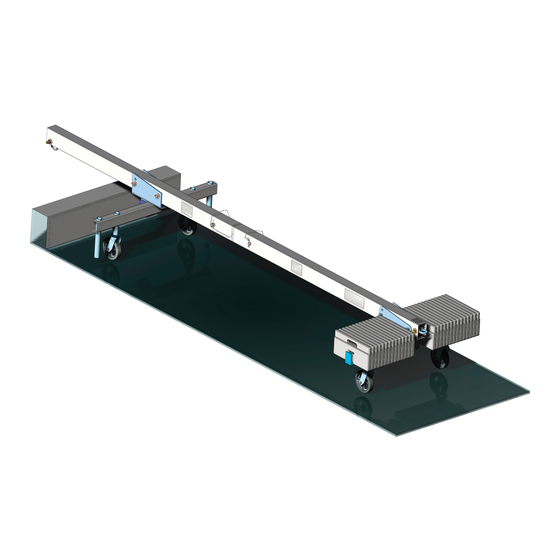
4' reach light skybeam
temporary outrigger beam for suspended platforms
United States: Boston: 1 800 421-0246 • Los Angeles: 1 800 675-6727 • griphoist.usa@tractel.com
Canada: Montreal: 1 800 561-3229 • Toronto: 1 800 561-3229 • griphoist.canada@tractel.com
© 2013 Tractel Ltd. All Rights Reserved.
assembly manual for
Tractel, Griphoist
4' Horizontal Beam
4' Inclined Beam
1
®
1,000 lb. (454kg) capacity
Division
®
Tieback
Required
Tieback
Required
Tieback
Required
Tieback
Required
Advertisement
Table of Contents

Related Manuals for Tractel Griphoist Skybeam

Summary of Contents for Tractel Griphoist Skybeam
- Page 1 Tractel, Griphoist Division ® United States: Boston: 1 800 421-0246 • Los Angeles: 1 800 675-6727 • griphoist.usa@tractel.com Canada: Montreal: 1 800 561-3229 • Toronto: 1 800 561-3229 • griphoist.canada@tractel.com 4’ Horizontal Beam Tieback Required...
-
Page 2: Table Of Contents
Set up of Outriggers and Counterweights 6. CHECKS BEFORE USING THE SKYBEAM Suspension Points and Support Equipment Tieback Platforms Wire Ropes Hoists 7. USE AND OPERATION OF THE SKYBEAM 8. INFORMATION FOR MAINTENANCE 9. SKYBEAM LABELS AND MARKINGS 22-23 © 2013 Tractel Ltd. All Rights Reserved. - Page 3 (i.e. record keeping): ® The 4' reach light skybeam is designed for a Maximum load of 1,000lbs (454kg). Do not use this system with a hoist of a greater capacity then 1,000lbs (454kg). © 2013 Tractel Ltd. All Rights Reserved.
- Page 4 Competent Person familiar with the skybeam for checking that all the instructions prescribed by this and professionally trained for the purpose. manual be regularly and efficiently carried out. © 2013 Tractel Ltd. All Rights Reserved. Draft #2 June 19, 2013...
- Page 5 32. Do not mix and match the 4' reach light skybeam and the 11’ skybeam components. Only use configurations as shown in this manual. © 2013 Tractel Ltd. All Rights Reserved.
- Page 6 3378 COUNTERWEIGHT - GRIPHOIST (55 LB/25 KG EACH) 28 by Griphoist HAC17W99 CASTER ASSEMBLY - GRIPHOIST 4 by Griphoist RBL0910 OPTIONAL SLIDING COLLAR PARTS RBC3080A LOCK PIN ASSEMBLY 3/4" DIA. c/w LANYARDS PARTS © 2013 Tractel Ltd. All Rights Reserved.
- Page 7 3378 COUNTERWEIGHT - GRIPHOIST (55 LB/25 KG EACH) 16 by Griphoist HAC17W99 CASTER ASSEMBLY - GRIPHOIST 4 by Griphoist RBL0910 OPTIONAL SLIDING COLLAR PARTS RBC3080A LOCK PIN ASSEMBLY 3/4" DIA. c/w LANYARDS PARTS © 2013 Tractel Ltd. All Rights Reserved.
- Page 8 11.9 3378 COUNTERWEIGHT - GRIPHOIST (55 LB/25 KG EACH) 28 by Griphoist HAC17W99 CASTER ASSEMBLY - GRIPHOIST 4 by Griphoist RBI1070B FRONT FRAME OPTION RBC3080A LOCK PIN ASSEMBLY 3/4" DIA. c/w LANYARDS PARTS © 2013 Tractel Ltd. All Rights Reserved.
- Page 9 11.9 3378 COUNTERWEIGHT - GRIPHOIST (55 LB/25 KG EACH) 16 by Griphoist HAC17W99 CASTER ASSEMBLY - GRIPHOIST 4 by Griphoist RBI1070B FRONT FRAME OPTION RBC3080A LOCK PIN ASSEMBLY 3/4" DIA. c/w LANYARDS PARTS © 2013 Tractel Ltd. All Rights Reserved.
- Page 10 3378 COUNTERWEIGHT - GRIPHOIST (55 LB/25 KG EACH) 28 by Griphoist HAC17W99 CASTER ASSEMBLY - GRIPHOIST 4 by Griphoist RBL0910 OPTIONAL SLIDING COLLAR PARTS RBC3080A LOCK PIN ASSEMBLY 3/4" DIA. c/w LANYARDS PARTS © 2013 Tractel Ltd. All Rights Reserved.
- Page 11 3378 COUNTERWEIGHT - GRIPHOIST (55 LB/25 KG EACH) 16 by Griphoist HAC17W99 CASTER ASSEMBLY - GRIPHOIST 4 by Griphoist RBL0910 OPTIONAL SLIDING COLLAR PARTS RBC3080A LOCK PIN ASSEMBLY 3/4" DIA. c/w LANYARDS PARTS © 2013 Tractel Ltd. All Rights Reserved.
- Page 12 For Assembly in the horizontal position go to section 4.4, the Front Beam (2) before connecting the unit together. for the inclined position go to section 4.5. Then slide the collar behind the front shackle. Fig. 2 Fig. 3 © 2012 Tractel Ltd. All Rights Reserved.
- Page 13 Fig 3. Connect the beams together with the provided 3/4" locking pin (5) and secure the locking pin with the for the inclined position go to section 4.5. hair pin (6) provided. Fig. 4 Fig. 5 © 2013 Tractel Ltd. All Rights Reserved.
- Page 14 Attach the front support (1) to the front leg (11) by slipping the Leg into the front support and aligning the holes and connect using the 3/4” locking pin (3) and secure with the hair pin (4). © 2012 Tractel Ltd. All Rights Reserved.
-
Page 15: Horizontal Version
The top is used when the beam configuration is for inclined position and the bottom used for the horizontal position. © 2012 Tractel Ltd. All Rights Reserved. - Page 16 (1) into the front frame (7) in the center post support and Two casters are required for the Single Counterweight align the holes and connect using a 3/4” locking pin (3) and secure Frame. with the hair pin (4). © 2012 Tractel Ltd. All Rights Reserved.
- Page 17 See Fig 13. See Section 4.4 Fig. 11 & 12 for proper tie back instructions. Locking Pin Fig. 13 Rear shackle and safety tieback as required © 2012 Tractel Ltd. All Rights Reserved.
-
Page 18: Assembly Instructions Other
Tieback wire ropes must have the equivalent strength to the hoisting ropes and must be installed without slack. NOTE: 1) Tieback may also be installed from the tip of the roof beam. When using the two tiebacks, one must be on each side of the beam. © 2013 Tractel Ltd. All Rights Reserved. - Page 19 Tieback wire ropes must have the equivalent strength to the hoisting ropes and must be installed without slack. NOTE: 1) Tieback may also be installed from the tip of the roof beam. When using the two tiebacks, one must be on each side of the beam. © 2013 Tractel Ltd. All Rights Reserved.
-
Page 20: Calculation Of Counterweights Skybeams (Reference)
Counterweights must be a nonflowable material, and they between A and B must be 16 foot and must be attached to the outrigger beam. 2 inches or greater. Always use tieback wire ropes capable of holding the full load. © 2013 Tractel Ltd. All Rights Reserved. -
Page 21: Set Up Of Primary Wire Ropes
28 counterweights are required. The three beam version requires 16 counterweights. Both beams have a 4’ reach and a 1,000lb (454 kg). Maximum capacity. Platform with Platform with Intermediate Stirrups End Stirrups a = b © 2013 Tractel Ltd. All Rights Reserved. -
Page 22: Checks Before Using The Skybeam
Check if the cable size of the power cord is sufficient. g. Ensure that guardrails are secured at proper height. d. Check that the hoists, Blocstop ® and emergency switches function properly. e. Check that power cord has strain relief to avoid damage. © 2013 Tractel Ltd. All Rights Reserved. -
Page 23: Use And Operation Of The Skybeam
A signed and dated report card should be maintained for these purposes. - Operating life of skybeam depends on number of hours in service, operating, weather conditions and proper handling of the beams. © 2013 Tractel Ltd. All Rights Reserved. - Page 24 Fig. 20 - Part #SPLB144A Fig. 21 - Part #SPLB145A Fig. 22 - Part #SPLB147A Fig. 23 - Part #SPLB148A Fig. 24 - Part #SPLB149A Fig. 25 - Part #SPLB146A Fig. 26 - Part #7112A0119 © 2013 Tractel Ltd. All Rights Reserved.
- Page 25 CONTINUED - LABELS AND MARKINGS FOR SKYBEAMS TIEBACK REQUIRED © 2013 Tractel Ltd. All Rights Reserved.
- Page 26 NOT S © 2013 Tractel Ltd. All Rights Reserved.
- Page 27 NOT S © 2013 Tractel Ltd. All Rights Reserved.
- Page 28 Tel: (514) 493-3332 Fax: (514) 493-3342 As we are dedicated to continuous improvement of our products, the TRACTEL GROUP reserves the right to modify the specifications of the equipment described in this manual. As a result, illustrations may not represent exactly the product you receive: components and/or design may differ.
Need help?
Do you have a question about the Griphoist Skybeam and is the answer not in the manual?
Questions and answers