Advertisement
Quick Links
T 800.285.6780 E sales@ggled.net
www.ggled.net
WPX
INSTALLATION MANUAL PAGE 1
WARNING:
Fixtures must be installed by a qualified electrician in accordance with all national and local electrical and
construction codes and regulations. Please read through this document entirely before beginning the installation.
NOTES:
1.) Ensure the last fixture in every daisy chain is capped. Each leader cable is packaged with an end cap. Failure
to cap the fixture will result in water ingress.
2.) Do not hot-plug fixtures. Ensure that power to the power supply is off before connecting or disconnecting
fixtures.
3.) White connector = power input. Mate with white plug on leader cable/jumper cable.
4.) Longer jumper cables may be sleeved through PVC (1"), EMT or Wire Mold if desired.
1. Confirm All Components Received
A.) Supplied Materials
-WPX Series Luminaire(s)
-WPX 48V Power Supply(s)
-Leader Cable(s) with End Cap(s)
-Jumper Cable(s) if applicable
-Mounting Clips
-Liquid-tight Cable Glands
STRONG.
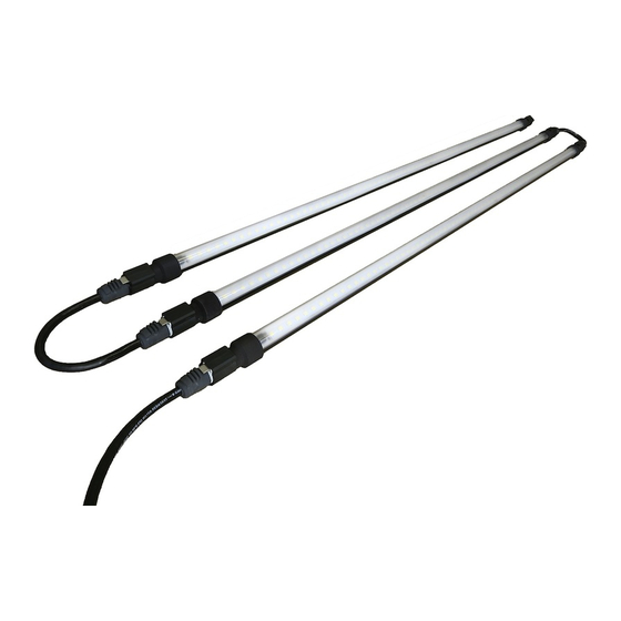
Multiple Fixtures; Quick-Connect Cabling
Single Fixture
B.) Required Materials
-Mounting Screws (depending on mounting surface)
SIMPLE.
Rev Date 19 0815
COMPACT.
IP68
IP69K
CERTIFIED
Advertisement

Summary of Contents for G&G WPX Series
- Page 1 4.) Longer jumper cables may be sleeved through PVC (1”), EMT or Wire Mold if desired. 1. Confirm All Components Received A.) Supplied Materials B.) Required Materials -WPX Series Luminaire(s) -Mounting Screws (depending on mounting surface) -WPX 48V Power Supply(s) -Leader Cable(s) with End Cap(s)
- Page 2 T 800.285.6780 E sales@ggled.net www.ggled.net INSTALLATION MANUAL PAGE 2 2. Verify Electrical Plan & Power Supply Load Verify the fixture layout, power supply and maximum load, using the tables below. Max Load Max Load Power Supply Enclosure Input Voltage Standard Output (SO) High Output (HO/Color) WPX-PSU-600 (600W) IP67 (Indoor/Outdoor)
- Page 3 INSTALLATION MANUAL PAGE 3 3. Mount Fixtures WPX series wet location fixtures are typically surface mounted (Ceilings, Walls, etc). If mounting on the ceiling, it is recommended to keep the fixtures 2-3 feet in from the wall. Mark the clip locations. If possible, use a chalk line and snap a line down the entire length of the run, where the fixtures are intended to be mounted.
- Page 4 T 800.285.6780 E sales@ggled.net www.ggled.net INSTALLATION MANUAL PAGE 4 5. Connect Fixtures Together Install the jumper cables between the mounted fixtures. The 1FT jumper (WPX-JMP1) may be looped for minimum distance between fixtures. Longer cables may be sleeved through PVC, EMT, or wiremold if desired. Figure 5.1: Fixture Jumper 6.
-
Page 5: Turn The Power On
T 800.285.6780 E sales@ggled.net www.ggled.net INSTALLATION MANUAL PAGE 5 8. Connect 0-10V Dimming Source (If Equipped) Only fixtures marked with a “-DIM” sticker are capable of being dimmed. G&G LED fixtures may be connected to all standard 0-10V dimming sources, such as wall dimmers, occupancy sensors, and lighting controllers. Please contact G&G Support with any compatibility or hookup questions.