Table of Contents
Advertisement
Advertisement
Table of Contents

Related Manuals for Neve 8424


Summary of Contents for Neve 8424
- Page 1 8424 User Manual Issue 1...
-
Page 2: Health & Safety Notice
Health & Safety Notice FOR YOUR OWN SAFETY AND FOR THE PROTECTION OF OTHERS PLEASE OBSERVE THE FOLLOWING HEALTH AND SAFETY INSTRUCTIONS READ THESE INSTRUCTIONS AND KEEP THEM HANDY • HEED ALL SAFETY WARNINGS • DO NOT USE NEAR WATER •... -
Page 3: Important Safety Instructions Usa
CAUTION Use only with the optional 8424 cart/stand specified by AMS Neve, or sold with the apparatus. When a cart is used, use caution when moving the cart / apparatus combination to avoid injury from tip-over. Use with other equipment may result in instability causing injury. - Page 4 Refer all servicing to qualified service personnel. Servicing is required when the apparatus has been damaged in any way, such as power-supply cord or plug is damaged, liquid has been spilled, or objects have fallen into the apparatus, the apparatus has been exposed to rain or moisture, does not operate normally or has been dropped.
-
Page 5: Warning Symbols
Warning Symbols Please refer to the manual before operating Danger of electric shock Disconnect from the MAINS before opening cover No user serviceable parts inside Environmental considerations Temperature Operating 5°C to 30°C (41°F to 86°F) Non-operating -20°C to 50°C (-2°F to 122°F) Max Gradient 15°C/Hour (59°F/Hour) -
Page 6: Important Safety Instructions Uk
Important Safety Instructions READ THESE INSTRUCTIONS AND KEEP THEM HANDY HEED ALL SAFETY WARNINGS THE CONSOLE MUST BE EARTHED WHEN OPERATED DO NOT USE NEAR WATER CLEAN ONLY WITH A DRY CLOTH DO NOT INSTALL NEAR HEAT SOURCES ... -
Page 7: Important Power Notice
IMPORTANT POWER NOTICE THE 8424 CONSOLE IS SUPPLIED WITH A 3-CORE AC POWER CABLE APPLICABLE TO THE REGION IT IS TO BE OPERATED IN, AND MUST BE CONNECTED TO A 3-PIN EARTHED SUPPLY. IF A REPLACEMENT CABLE IS USED, THEN THE EARTH FROM THE... -
Page 8: Table Of Contents
Cue Talkback ......................30 DC Remote Pin out Functions ..................67 Slate Talkback ......................30 2T VU MTR Pin out Functions ..................67 Return Talkback ......................31 8424 Audio Specification ......................68 Talkback Footswitch ....................31 General Specification ......................69... -
Page 9: Introduction
Web: www.ams-neve.com © ® 2005 - 2020 AMS Neve Ltd own the copyright of all information and figures contained in this manual which are not to be copied or reproduced by any means or disclosed in part or whole to any third party without written permission. As part of our policy of continual product improvement, we reserve the right to alter specifications without notice but with due regard to all current legislation. -
Page 10: Console Overview
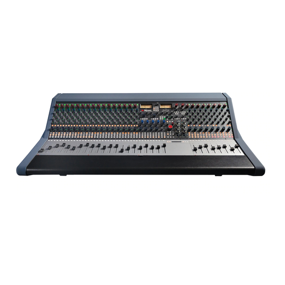
Console Overview Channels 1 – 16 Master Section Channels 17-24 8424 Console Features • 24 Mono channels with source selections and 100mm faders • 24 Channel Direct Outputs • 4 Groups with 100mm faders • 3 Mono Auxiliary sends •... -
Page 11: Channel Strip Overview
Channel Strip Overview Direct Out Pre A/B Input select Input Trim Channel Meter Stereo Cue Pan Stereo Cue Send Aux Sends 1-3 Channel Insert Insert to Input C Channel Pan GRP Pan Channel Routing Channel solo/cut Channel Fader... -
Page 12: Master Section Overview
Master Section Overview Aux/Cue masters Headphone 2 Stereo VU Meters 1073 Preamps Reverb Returns Instrument DI’s Global Controls 500 Series Slots Group/Mix EQ Stereo Width Control Room Monitor Section Group Pan Talkback Group/Stereo Controls Mix Routing Routing Stereo Mix Cut Group Solo/Cut Services Screen Mix Fader... -
Page 13: About This Manual
There is also a table explaining the Acronyms and Abbreviations of the most commonly used buttons and functions on page 58 of this document. Many rotary controls on the 8424 have a push-activation ON/OFF function. Simply push the pot to switch the control ON or OFF. -
Page 14: Power Procedure
Turn the amp (or speakers) to the desired level. On the 8424, ensure that the Control Room level is turned down and un-cut the monitoring (as a safety feature, the monitoring system will always be CUT when first switching the system on). -
Page 15: Quick Start
Reverb returns/EXT/500 series/1073 inputs – XLR x10 Boot Mode Upon start-up, the 8424 is configured with all channel inputs on Input B. This can be changed by switching the inputs individually on each channel, or by pressing the global A/B CH IP switch in the master select section of the console. -
Page 16: Studio Setup
Studio Setup Loudspeakers A, M1, M2 DI Instruments Microphones Line Level Artist Instruments Headphones External Preamps 1073 & DI EHP 2 Line Input B Line Input B Monitor 1-16 Outputs inputs 17-24 DAW Returns Input A 1-24 Insert Insert Reverb Returns Sends Sends... -
Page 17: Channel Strip
Channel Strip Overview One of the core design concepts of the 8424 is that each channel can select its input from two alternative line input sources. This enables the 8424 to be used for Mixing, Recording and Overdubbing. The A/B CH IP switch on every channel will select either channel Input A (DAW Interface Outputs) or channel Input B for line level instruments or external preamps. -
Page 18: Input Trim Encoder
MAST>ZERO IP B. To globally reset DAW returns Input A select MAST>ZERO IP A. Channel Meter Each Channel on the 8424 has its own 8 stage PPM input level meter which displays input signal levels from -30dB through to +24dB. Levels below 0dB illuminate... -
Page 19: Stereo Cue
Stereo Cue Each Channel on the 8424 has a stereo cue send which can send audio from channel input A or B (depending which input is selected on the top of the channel strip) to performers in the live/control room. The CUE send can also be used as a stereo FX send. -
Page 20: Aux Sends 1-3
Note: Channel insert sends are always active. This allows a second pre-fade direct out from each channel. The 8424 pan-pot runs from 0dBu hard left, - 4.5dBu centre to 0dBu hard right positions. The channel Pan-Pot functions for both Input A or Input B depending on the selected channel input. -
Page 21: Channel Routing
In addition to the channel routing, the cue bus can also be routed to groups 3 & 4, this feature is useful when using the 8424’s In-Line monitoring mode. Any DAW output sent to the channel cue I/P A or I/P C can rerouted from... -
Page 22: Groups 1-4
Groups 1-4 Overview The 8424 features 4 mono Groups with 100mm Faders located in the centre of the console. These groups can be used for a variety of functions such as sub-mixing instrument groups, using group processing on selected instruments, balancing large amounts of instruments or as separate masters for the cue mix bus when using the consoles in-line mixing mode. -
Page 23: Solo
Solo The SOLO button will isolate the selected Group channel into the Stereo Mix bus and group outputs. The Group solo is destructive by default (SIP) but can be set to non-destructive modes; Pre-fader PFL or After-fader AFL which is set in the control room monitor section of the console by pressing the AFL/PFL level control or by Isolating on a channel by channel basis. -
Page 24: 1073 Preamps
. The 8424 1073’s have Smart Routing, enabling them to be routed to console channels 17 & 18 at the push of a button with no patching required. -
Page 25: Instrument Di Inputs
Inputs Overview In addition to the two 1073 microphone preamp inputs, the 8424 has two 760 kΩ Instrument DI channels that can be routed to various points on the console. The Instrument DI inputs are ¼’’ Jack connectors (balanced or unbalanced) that are located conveniently underneath the front of the console. -
Page 26: 500 Series Slots
Instrument D.I. (before smart routing to channels 19/20) Direct Input/Output In addition to the group, mix, preamp and DI routing options, the 8424 500 series units can be used as standalone hardware units by using the XLR in/out connections on the rear of the console. This allows the 500 series slots to function as a separate hardware rack, independent of the console. -
Page 27: Reverb Returns
Reverb Returns Overview The 8424 console features two dedicated stereo reverb returns which are fed by the XLR inputs on the rear of the console. The reverb returns can be used to return stereo effect unit outputs into the console or as additional stereo line level inputs should you require more line inputs. -
Page 28: Aux & Cue Masters
Aux & Cue Masters Overview The Three mono AUX master and stereo CUE master controls are located above the control room monitor section of the console. Each pot runs from inf to 0dB and has push-activation. When pressed, the AUX/CUE master bus is active and the ON light will illuminate Each aux master and cue master can be soloed by pressing the AFL button which illuminates... -
Page 29: Engineer Headphones
Engineer Headphones Overview The 8424 engineer's headphone system [EHP] has been designed to help & enhance the modern recording session for the engineer, the producer and the artist. Artist and engineer can track in the control room with their own stereo headphones, featuring independent level controls and source selections. -
Page 30: Talkback
Talkback Overview The talkback function on the 8424 enables three-way communication between the engineer, producer and the performers. The 8424-talkback microphone and talkback master level control are located at the top of the console, in between the two VU meters. When talkback is engaged, the monitors in the control room are dimmed to allow for clear communication. -
Page 31: Return Talkback
TB>RTB ENABLE: [Y] Talkback Footswitch The 8424 Console also has a talkback on/off footswitch control that is accessed via the DC REMOTES D-sub connection on the back of the console (Pin 4). Once connected the footswitch will run parallel to the CUE TB on the console surface. -
Page 32: Solo Modes
SIP Solo-in-Place Solo in place is the 8424 default solo mode. SIP is destructive, any channel solo will mute all other console channels. SIP sends the soloed channel signal through the stereo mix bus. All 24 channels 4 mono groups can be soloed-in-place as well as console inputs 25-48 when in 48-Mix mode. -
Page 33: Global Solo Controls
MAST>SOLO: [LATCH]/[MOM] Latch mode – Affects SIP/AFL/PFL and is the 8424-default solo switch setting. This setting allows for multiple console signals to be pressed and soloed at the same time. Solos will remain on until the engineer deselects the solo switch on each soloed channel or by pressing the RESET button in the global console controls section of the 8424. -
Page 34: Master Controls
AFL/PFL. RESET Wipes any active console solo, does not affect ISO. 48 MIX A unique 8424 function that enables 48 individual inputs to be mixed through the console simultaneously. Pressing 48 MIX changes several routing options on the console. •... -
Page 35: Stereo Mix Processing
Stereo Mix Processing Overview The 8424 Stereo Mix bus features two Neve classic Marinair® transformers for high-headroom, voltage mixing. Two XLR outputs labelled MIX O/P on the rear of the console allow for recording the consoles final Stereo Mix by patching into the DAW, tape machine or external recording device. -
Page 36: Pre
Mix O/P L/R XLR Master Fader The 8424 Stereo Mix fader is a 100mm precision stereo fader that controls both the Left and Right outputs of the console. The master CUT will mute the master mix bus from the control room... -
Page 37: Control Room Monitor
Control Room Monitor Overview The Control Room Monitor section of the 8424 gives total control of the Stereo Mix monitoring outputs and is the loudspeaker output attenuation control for the 8424 console. The monitor section of the console is positioned in the centre to allow easy access to the essential controls. -
Page 38: Vu Meter
VU Meters Overview The 8424 console features 2 large backlit VU meters which display level in Volume Units. The VU meters can be used to monitor a number of different console signal sources. -
Page 39: Services
Services The 8424 Services screen allows users to globally select master controls, engage Talkback and reverse talkback options controls and access and assign the oscillator functions. The services screen is a 16-character digital display that shows the top menu titles MAST, TALK, OSC, SYSTEM. The buttons allow access to each control. -
Page 40: Talkback Options
System SAVE –Saves current console state to the 8424 internal memory See Page 41 LOAD – Loads a console store from the 8424 internal memory See page 42 DHCP: [Y/N] – for use when preforming firmware updates from the Neve Updater App. -
Page 41: Recall Store System
The 8424’s internal Recall feature allows operators to save and load console switch settings, fader positions and hard pots within the 8424 internal memory. 8424 settings can be saved and recalled on a session-by-session basis enabling a fast, analogue console workflow that takes advantage of all features while remaining creative, efficient and productive. -
Page 42: Load
Once the save process is complete, switch settings, channel trims, pot positions, and fader levels are now stored, along with the master section switch settings, pot positions and fader levels. 8424 settings exempt from the console store – • Talkback Level •... - Page 43 To load a Recall Store – Enter SYSTEM menu and select [LOAD] The following window will appear – Choose a Recall Store from [1] to [99], toggle through stores by pressing ENTER, or to toggle 10 at a time press CTRL + ENTER. ...
-
Page 44: Auto Scan
Once the Snapshot loads (following a 2 second delay), the Recall store load process will prompt the user to begin the recall procedure. Select [OK] to begin the recall procedure. If hard pot/fader recall is not required, select [CANCEL] Auto Scan The Recall auto scan starts once OK has been pressed. - Page 45 Once the pot is in the correct position <MATCHED> will momentarily appear on the screen. The pot position now matches the console store. The auto scan process will continue until it discovers another pot or fader position out of place from the saved Recall store.
-
Page 46: Manual Recall
Manual Recall At any point during the auto scan process users can enter manual recall mode. This mode of operation allows users to manually recall individual channel settings or master section settings without having to auto scan and recall the entire console. To manually recall a selected channel, simply press the channel SOLO button during the auto scan process. -
Page 47: Return Talkback Options
Return Talkback Options Overview The 8424 includes a Return Talkback feature that can be used in three different ways depending on your studio requirements. The Return Talkback system has its own microphone controls, Gain, Phantom power and Compressor circuit. The Mic Gain level is controlled from the RTB GAIN trim controller at the rear of the console. -
Page 48: Producers Sofa Mic
Producers Sofa Mic As an alternative, the 8424 return talkback can be used to create a second talkback feed from the control room into the live room. In this mode, the RTB signal is not sent to M2, (as is the case for the Live Room Return Talkback mode) but instead is sent to the CUE bus. -
Page 49: Service Outputs (Dc Remotes)
Service Outputs (DC Remotes) The 8424 console has a 15-Pin, 5 Channel D-Type connector on the rear of the console, Labelled as DC Remotes. These service outputs allow for several external control options and can be controlled by a number of custom-built remote switches or connected footswitches. -
Page 50: Example Applications
Group direct outputs, or bounced as individual stems back into the DAW by using the channel Direct Outputs. The 8424 has Marinair® Transformers on its Stereo Mix bus for true Voltage mixing. The processing on the master section of the console (Group/Stereo Mix EQ’s, Stereo width control, Channel, Group or master hardware inserts, 500 series inserts) allow for versatile tone shaping of Group signals and the main Stereo Mix signal. -
Page 51: Recording
Example Application – Recording When recording through the 8424 console, Input B allows individual line-level signals to be patched directly into the channel inputs via the ¼’’ balanced jack connections at the rear of the console. Any external Preamp line outputs can also be patched into the console via Input B, allowing multiple microphone sources to be recorded through the console surface. -
Page 52: Overdubbing
DAW return channels. Globally select Input A to return your previously recorded DAW tracks back through the 8424’s 24 channels. Overdubs can be recorded on any chosen channel 1 to 24 by selecting Input B as its channel input source. The selected channel will be setup to feed the channel Direct output into the DAW ready to record an overdub track. -
Page 53: Input Mix Mode
48 Mix Mode This mode of operation doubles the channel count of the 8424 console and enables 48 separate mono DAW inputs to be mixed simultaneously. This mode splits the console into two layers - The channel faders (I/P A) will input DAW interface outputs 1-24 and the ST CUE bus uses Input (I/P C) to input DAW interface outputs 25-48. -
Page 54: In-Line Mode (Ilm)
In-Line Mode (ILM) The 8424 is capable of functioning as an In-line studio console, with the ST CUE level control becoming the monitor return ‘Small Fader’. This allows for simultaneous mixing of both recording line inputs (I/P B) on the channel faders and monitor return inputs (I/P A) on the ST CUE controls. -
Page 55: Parallel Processing
Parallel Processing The 8424 has the capability of sending Input A (DAW interface Outputs 1-24) to two locations on the same channel strip. Both into the main channel input and into each channel CUE Input. This is the same function that enables In- Line Mode (ILM). -
Page 56: Audio Interface Setup
32 I/O Audio AD/DA Interface A 32 in 32 out AD/DA audio interface allows for full functionality of the 8424 console. with this setup, 24 DAW returns can be patched into all channel inputs via Input A, and a further 8 can be patched into Input C. This enables simultaneous summing of up to 32 individual audio channels through the console using 48 MIX mode. -
Page 57: Firmware Update Software
Run the installer package on your PC/MAC and follow the on-screen steps. Once installed the software is ready to be connected to your 8424 Console. Once connected and scanned the software will prompt the user to begin firmware update if required. - Page 58 • Lower thin grey progress indicator is overall progress. The 8424 front panel will enter boot mode when programming, please do not press any buttons on the unit during this process. Units can be renamed by clicking rename (Max 21 characters) Identify not in use.
-
Page 59: Abbreviations And Acronyms
Abbreviations & Acronyms 48 MIX 48 Mix Mode 500 1/2 500 series slots 1/2 500-1 500 series Slot 1 500-2 500 series Slot 2 Analogue to Digital Converter After Fader Listen Channel Cue send CUE O/P L+R Cue Output Left and Right CUE TB Cue Talkback Digital to Analogue Converter... -
Page 60: Dimensions & Power Requirements
Dimensions & Power Requirements Console Physical / Technical Information Height 500mm/19.68 inches To top of LS Shelf (No Stand) Height 990mm/38.98 inches To Top of LS Shelf (With Stand) 1190mm/46.85 inches Width (24 Channel) Depth (24 Channel) 850mm/33.46 inches Weight (no stand) 53kg Weight (with stand) 64kg... -
Page 61: Console Rear Connections
Console Rear Connections Power Unit Channel Inputs... -
Page 62: Master Inputs/Outputs
Master Outs Monitor connections... -
Page 63: Console Connections Table
Console Connection Tables Main Console AC Mains, fused @ 4 amps IEC males Channel Line Inputs B ¼" TRS Jack sockets Channel DAW Return Input A 25-way D-Type, Tascam convention Channel Input C 25-way D-Type, Tascam convention Channel Insert Send ¼’’... -
Page 64: Channel Inputs A/Daw Returns
Channel Input A/DAW Returns 1-24 D-Type 25-Way Pin Outs CH DAW RET I/P A 1-8 (25-way D-type) Signal Name Screen I/P A Input 1/DAW Return 1 I/P A Input 2/DAW Return 2 I/P A Input 3/DAW Return 3 I/P A Input 4/DAW Return 4 I/P A Input 5/DAW Return 5 I/P A Input 6/DAW Return 6 I/P A Input 7/DAW Return 7... -
Page 65: Channel Inputs C/Daw Returns
Channel Input C/DAW Returns 16-48 D-Type 25-Way Pin Outs Input C 1-8 (25-way D-type) Signal Name Screen I/P C Input 1/DAW return 25 I/P C Input 2/DAW return 26 I/P C Input 3/DAW return 27 I/P C Input 4/DAW return 28 I/P C Input 5/DAW return 29 I/P C Input 6/DAW return 30 I/P C Input 7/DAW return 31... -
Page 66: Channel Direct Outputs
Channel 1-24 Direct Outputs D-Type 25-way Pin Outs Direct outputs 1-8 (25-way D-type) Signal Name Screen Direct Out Channel 1 Direct Out Channel 2 Direct Out Channel 3 Direct Out Channel 4 Direct Out Channel 5 Direct Out Channel 6 Direct Out Channel 7 Direct Out Channel 8 Direct outputs 9-16... -
Page 67: Line Inputs And Outputs
Line Inputs & Outputs All ¼’’ Line Inputs & Outputs on the Console have the same wiring Ring Cold Sleeve Ground XLR Inputs & Outputs All XLR Inputs & Outputs on the Console have the same wiring Pin 2 Pin 3 Cold Pin 1 Ground... -
Page 68: 8424 Audio Specification
8424 Audio Specification Line Input B to Direct Output Headroom +27.7dBu @ 1kHz (<0.5% THD+N) Frequency Response Typically +/- 0.1dBu, 20Hz to 20kHz Distortion (THD+N) Typically 0.004% @ 1kHz (measured at +10dBu 10Hz to 80kHz filter) Noise <-88dBu (20Hz to 22kHz filter) -
Page 69: General Specification
General Specifications 1073 to Channels 17 & 18 Headroom +27.7dBu @ 1kHz (<0.5% THD+N) Frequency Response Typically +/- 0.1dBu, 20Hz to 20kHz Distortion (THD+N) Typically 0.003% @ 1kHz (measured at +20dBu, 10Hz to 80kHz filter) <-87dBu (20Hz to 22kHz filter) Noise DI to Channels 19 &...
Need help?
Do you have a question about the 8424 and is the answer not in the manual?
Questions and answers