Table of Contents
Advertisement
Quick Links
Advertisement
Table of Contents

Related Manuals for Neve GENESYS BLACK


Summary of Contents for Neve GENESYS BLACK
- Page 1 User Manual Issue 1.2 Version 3.4 software Build 2 or later 527-405...
- Page 2 IMPORTANT SAFETY INSTRUCTIONS u Read these instructions u Keep these instructions u Heed all warnings u Follow all instructions u Do not use this apparatus near water u Clean only with a dry cloth u Do not block any ventilation openings. u Install in accordance with the manufacturer's instructions.
-
Page 3: Important Safety Instructions
u Unplug this apparatus during lightning storms or when unused for long periods of time. u Refer all servicing to qualified service personnel. Servicing is required when the apparatus has been damaged in any way, such as power-supply cord or plug is damaged, liquid has been spilled, or objects have fallen into the apparatus, the apparatus has been exposed to rain or moisture, does not operate normally or has been... -
Page 4: Symbols Used In This Manual And On Rear Of Console
Symbols used in this manual and on rear of console Please refer to the manual before operating Danger of electric shock Disconnect from the MAINS before opening cover Heat source No user serviceable parts inside Environmental considerations Temperature Operating 5°C to 22°C (41°F to 72°F) Non-operating -20°C to 50°C... - Page 5 - 5 -...
-
Page 6: Health & Safety Notice
Health & Safety Notice FOR YOUR OWN SAFETY AND THE PROTECTION OF OTHERS, PLEASE OBSERVE THE FOLLOWING SAFETY HEALTH AND SAFETY INSTRUCTIONS READ THESE INSTRUCTIONS AND KEEP THEM HANDY HEED ALL SAFETY WARNINGS THE CONSOLE MUST BE EARTHED WHEN OPERATED DO NOT USE NEAR WATER CLEAN ONLY WITH A DRY CLOTH DO NOT INSTALL NEAR HEAT SOURCES... -
Page 7: Important Notice
IMPORTANT NOTICE THE GENESYS CONSOLE IS SUPPLIED WITH A 3-CORE AC POWER CABLE APPLICABLE TO THE REGION IT IS TO BE OPERATED IN, AND MUST BE CONNECTED TO A 3-PIN EARTHED SUPPLY. IF A REPLACEMENT CABLE IS USED, THEN THE EARTH FROM THE MAINS SOCKET OR TECHNICAL EARTH TO THE CONSOLE MUST BE MAINTAINED. -
Page 8: Console Overview
Two stereo mix busses (Main Mix LR + 2T) • Two stereo monitoring speaker sets • Two 5.1 monitoring speaker sets • 8 channels of Neve mic/line amplifiers • 16 dedicated DAW control faders with corresponding stereo DAW metering on meter bridge • 8 mono Groups •... -
Page 9: Introduction To Genesys Black
Please check the AMS Neve website periodically for the latest issue of this manual. © ® 2008 - 2015 AMS Neve Ltd own the copyright of all information and figures contained in this manual which are not to be copied or reproduced by any means or disclosed in part or whole to any third party without written permission. -
Page 10: Table Of Contents
ISO..............50 DMON LED............51 Master SEL Mode on the Channel Strip....32 SEL..............51 Master SEL Mode on the 8T Section....32 >8T..............51 Master SEL Mode on the Monitor Panel....32 SWP..............51 SOLO..............51 An Overview of the Genesys Black Signal Flow CUT..............51 - 10 -... - Page 11 TO MON leds.............51 DLN LED............61 SWP..............62 Preventing feedback loops........51 MIX..............62 CH SAFE............62 REVERB RETURNS / AUX MASTERS Section MON SAFE............62 8T SAFE............62 I/L..............63 REV Return Section..........53 LATCH..............63 TO CUE.............53 RESET..............63 WIDTH..............53 LINK..............63 PAN/BAL............53 DAW SND............63 MONO...............53 DAW RET............63 ON..............53 I/P 2 & DMON LED..........63 ISO..............53 AFL..............53 ROUTE SEL...
- Page 12 Master SEL mode on the CONTROL ROOM MONITOR VU..............92 Section..............77 PPM..............92 To Enter and Exit Master SEL Mode.......77 SET..............92 To Tie a Set of Speakers to the Stereo DownMix..77 PEAK..............93 To Lock Relative Levels Within a Loudspeaker Set. . .78 P/HOLD.............93 To Lock the S and LS/RS to Sets of Loudspeakers.
- Page 13 Calibrate............112 Board States............133 Channel FNC Control.........112 Switchblock 2..........133 Console Utilities..........112 Board ID............133 Services............112 WCLCK 75Ω Termination........134 DAW Type...........112 Channel Slave............135 MIDI Port Assignments........112 Overview............135 MTC Ethernet MIDI........113 Connectors & Switches........135 As Was Snapshot.........113 AES RX DLINE / AES TX........135 Console Debug Window.........113 AES RX DMON..........136 FireWire Setup..........113 Channel Slave Audio Link........136...
- Page 14 Genesys Audio Specification PLI (Plug-ins)..........170 FADS and BANKS........171 Record Mode............204 AUTO.............171 Mix Mode............204 CHAN.............171 General Specifications........205 t and u Buttons........171 TRANSPORT..........172 Genesys Black Physical Information SOLO/CUT..........172 Dimensions............206 Apple Logic Pro..........173 Connector Types..........206 Genesys Setup..........173 Apple Logic Pro Setup........173 Console Connector pin-outs Operation............174 Ch V-Pot Select (Genesys software)....175...
- Page 15 Master AD/DA Channels cassette, SMN 812–409 FireWire 1 & 2..........221 .................218 AES TX 8T/AES RX DEXT........221 AES RX DLN / AES TX / DAW SEND.....218 AES TX/AUX/2T L&R/MIX L & R/AES SYNC In/Out..222 AES RX DMON / AES SYNC In/Out.......218 Serial Connectors..........222 Serial 1 , 2 &...
-
Page 16: About This Manual
About this manual This manual consists of: A section-by-section operational overview of all parts of the console • surface Technical & physical specifications including power consumption, • dimensions, weight and other relevant information Schematics and reference drawings of D-Type pin-outs etc. •... -
Page 17: Abbreviations & Acronyms
Abbreviations & Acronyms 8 Track Power Supply Unit After Fader Listen Return Calibrate Reverb Channel Return Talkback Channel Mic Control Room Monitor Select Digital Audio Workstation Solo In Front D-EXT Digital External(s) Signal Digital Line(s) Send Dynamics Swap DMON Digital Monitor Talkback External(s) UTIL... -
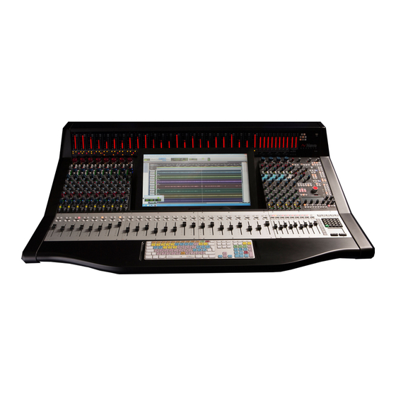
Page 18: The Computer Cassette
The Computer Cassette This computer cassette IMPORTANT: has the optional Monitor Section Digital Before powering up the console, please connect an external monitor Board fitted. The screen to the DVI 1 connector. The console software cannot be used connectors on the without a screen connected. -
Page 19: Important Notice
• goes blank, please wait for another 10 seconds before removing the power to Genesys Black using the switch on the rear of the meter bridge. This is because stopping the graphical output to the screen is not the last thing that the computer does before shutting down, it will continue to write files for a short while afterwards. -
Page 20: Optional Console Hardware
1084 EQ Cassette (Part number SMN 812-411) The assembly number is AM 5644. This cassette provides 8 Channels with classic Neve 1084 EQ (3 bands per channel). Without this card (or the 88R EQ card), the EQ button (and LED) on each channel strip will not function. -
Page 21: Dynamics Cassette
Dynamics Cassette (Part number SMN 812–412) The assembly number is AM 5645. The Dynamics cassette provides 8 channels with Dynamics processing (Compressor and Gate, including the provision of an external Key Input). This external Key Input is available on both the Gate and Compressor. Without this card, the DYN button (and LED) on each channel strip will not function. -
Page 22: Channels Digital Converter System
Channels Digital Converter System (Part number SMN 812–409 Master and Slave) This cassette provides 8 channels with AD/DA converters. Depending on the digital channel requirements, a Master or Master and Slave card can be installed in groups or individually. Without this card, the DLN and DMON functionality (and leds) will not be available on the console. -
Page 23: Monitoring Digital Converter System
Screw the faceplate onto the chassis (highlighted in red above). • For more information on optional software & hardware, please contact your local Neve distributor. - 23 -... -
Page 24: Touch-Screen
Windows 7 or newer. For Mac systems the required driver may have been supplied with the console. If not it can be obtained from AMS Neve by filling out a support form online at http://ams-neve.com/support/console-fault-report and stating that the Genesys Black touch-screen driver is needed. - Page 25 After the installation has completed, the driver needs to be configured: Open the UPDD Console app (located in the Utilities folder inside the Applications folder). Set the configuration as shown in the attached image. (Click Mode set to Interactive touch, Interactive switch delay set to about 65%).
-
Page 26: Daw Control
Ethernet cable for DAW fader control (from Genesys computer) • When using hubs/switches, only standard Ethernet cables should be used. When not using a hub and connecting the Genesys Black computer directly to the DAW computer an Ethernet crossover cable may be needed. -
Page 27: Daw Computer Settings
DAW Computer Settings Mac OS X (DAW Computer) On your Mac DAW computer, from the Apple menu, select System Preferences / Network. From the resulting screen; When not using a hub/studio network and connecting the Genesys computer directly to the DAW computer using a crossover cable: Select Ethernet 1 (or the primary/connected ethernet connection) in the left hand window, and select Manually from the pull-down menu next to Configure IPv4. -
Page 28: Windows Vista (Daw Computer)
This is a 3 party driver that allows communication data to be sent between the Genesys Black and the DAW computer. This driver only needs to be installed on your DAW computer (not the Genesys computer). There will be two available, one for Windows and one for Mac OS X. -
Page 29: Windows Vista / 7 (Daw Computer)
FOR TOUCH-SCREEN DRIVER INSTALLATION ON MAC SYSTEMS PLEASE REFER TO THE SEPERATE MAC TOUCH-SCREEN DRIVER INSTALLATION DOCUMENT AVAILABLE FROM AMS NEVE SUPPORT Once the above setup for DAW control (ethernet connection - direct or hub, IP addresses, and driver settings) is completed you are ready for DAW control. -
Page 30: Modules Overview
Modules Overview None of the Genesys modules contain any user serviceable parts, and should they develop a fault, they will always need returning to AMS Neve for repair (or to one of our officially nominated Service Centres). Channel Input Module These modules do not have any addressable switches, and can be freely swapped to any other Channel position on the console. -
Page 31: Hot-Plugging
Push the module until it makes a secure connection with the backplane. There are two audio connectors on each module (either side of centre) that mate into the console backplane. Replace any connectors removed from the rear of the module (eg Mic/Line) Failure to make sure the module is seated correctly in the chassis, can result in missing audio busses and incomplete functionality on a module. -
Page 32: Genesys Power Up/Down Procedure
(if using active speakers, turn each speaker down before removing the power). From the main Genesys Black screen, click the System button. On the System Diagnostics screen that opens, click Turn Off Console. You will be asked to confirm your actions. -
Page 33: Master Sel Mode
Master SEL mode Master SEL mode is entered, by holding down the LOCK button on the Main Monitor Panel, and then pressing RTE SEL. All of the SEL buttons on the Channel and 8T strips will flash to indicate the console is in Master SEL mode. This is a setup mode that allows you to set the Pre/Post state of auxes, set loudspeaker locks, the order of processing on the channels etc. - Page 34 If RTE SEL is pressed without using the LOCK button, then RTE SEL Mode provides purely a routing function, and is used for sending Channel and/or Monitor paths to either the 8T and/or Main Mix busses Coming out of Master SEL Mode returns all audio, leds & buttons to their last selected display and state.
-
Page 35: An Overview Of The Genesys Black Signal Flow
Genesys Black is an Inline mixing console – this means it has both Channel input and Monitor input paths in each channel strip. In this way, a 8-channel Genesys Black also has another 8 Monitor inputs, in effect turning it into a 16-input desk. - Page 36 Small Fader on a traditional large-format analogue console. Also, when using Genesys Black for recording to Pro Tools, instead of sending the input directly to the relevant track on Pro Tools (so Input 1 goes to Track 1), it is possible to route a collection of signals to any of the 8T faders, which in turn can then be sent to Pro Tools.
-
Page 37: Recording In Stereo
DAW via analogue connections, FireWire, or MADI. When the console is booted for the very first time, the AMS Neve default Stereo Recording Setup will be sent to the console. This sets the states of various controls, routing, metering and monitoring selections, and presumes that the console will be used for recording in stereo. - Page 38 If you wish to record from a Line or DAW source, press the +/-15 pot at the top of each Channel strip to select the desired input. The monitoring is already selected to the Main Mix, so once the loudspeakers have been un-CUT, pushing up the Mix LR and channel faders (or turning the Mon knob up) will send audio to the speakers.
-
Page 39: Mixing In Surround
Mixing In Surround Configuring Genesys for Surround The channel strips on Genesys Black are fitted with LCR pan pots, as well as stereo, which means that panning from left to right will send the audio from Left, through Centre, to Right. -
Page 40: Panning
Once the LCR surround system has been set up, it will be useful to save as an LCR surround template for future use. Panning The audio can be sent to the 8Ts Pre- or Post- the Pan control: If the Pan LED is lit red (LCR), then the audio will be Post-pan •... -
Page 41: Mixing With Stereo Pans In Surround
Mixing with Stereo Pans in Surround Using the L/R surround template, we can now add to it and create a complete Surround Routing template. It is possible to create a Stereo mix and a 5.1 Surround mix and output them both from the console at the same time. The Surround mix is configured by using six of the 8T busses (plus Aux 1 and Aux 2 to supply discrete feeds to the Centre and Sub speakers). - Page 42 Speaker Press and hold the LOCK button on the Route SEL panel and then press the RTE SEL button to put the panel into Master SEL mode. Press 8T (just above the monitoring knob). The following takes place in Master SEL mode: It is now possible to scroll the LS alpha display through all of the 8T Outputs using the large Main Monitor Knob.
-
Page 43: Monitoring
The Auxiliaries can be fed from either the Channel or Monitor, • either Pre- or Post- fader. By default, this is set to Channel input, Post-fade. The shaded area with a dashed border above indicates you must put the console into Master SEL mode before setting the speaker mapping. Monitoring On the Monitor Panel, press either A or B to select the Surround speaker set. - Page 44 (INT) and the Surround Return from it (EXT). If you have the 8T Insert audio connections in place, you will be able to compress the entire Surround mix (for example using the Neve 8051 Surround Compressor) by pressing the INS buttons above each of the 8T faders 1, 2, 5, 6, 7 and 8.
-
Page 45: Channel Strip
Channel Strip CHANNEL Section The free-running Input Level knob boosts the Input Gain in 11 discreet steps and has a range of +20dB to +70dB, the level being displayed using internal leds. It is also a 3-state toggle control, and pushing the knob will cycle through: CHM: Selects the Channel / Mic input gain, as outlined above. -
Page 46: Input Trim
INPUT TRIM This supplies +/- 15dB of trim to the incoming Channel signals. Press the control to cycle the input selection through MIC/LN/DAW/DLN, shown on the adjacent leds. Pans LCR Pan Pan control. Press to enable. The adjacent LED will light yellow if it is set to work as a conventional L/R pan, or red if set to work as an LCR Pan (as set in the Routing Screen). -
Page 47: Processing Section - Eq, Dyn, Ins
PROCESSING Section – EQ, DYN, INS If the optional EQ and Dynamics processing cassettes are present, it is possible to place the EQ and/or Dynamics on either the Channel or Monitor path (it is not possible to split the Dynamics elements so the Compressor and Gate are split between the two paths). -
Page 48: Channel And Monitor Path Drag And Drop Order Processing (Ord Button)
Channel and Monitor Path Drag and Drop Order Processing (ORD Button) You can manually control the channel processing order using the ORD button on the Channels to set/show the order processing of the EQ/DYN/INS1/INS2 (elements). However, it is also possible to set the processing order by using the click, drag and drop method as well. -
Page 49: Auxes Section
AUXES Section Master Aux Level Sets the output contribution of the Aux. It has a range of -∞ to 0dB. Press to enable, and the adjacent LED will light. >8T buttons Sets the destination and level control for sending the Auxes to the last two 8T busses Different destinations apply depending on whether the Aux is mono or stereo. -
Page 50: Direct Output Section
DIRECT OUTPUT Section Master Level Sets the level of the Direct Output, and has a range of -∞ to +10dB. In it's default state there will be no output and all of the associated leds will be unlit (Off). The control is a 6-state toggle, and pressing it will cycle the Direct Output to be fed from (1 press): Channel input, Pre processing, Pre fader, Pre CUT (PRE LED lit) -
Page 51: Monitor Section
Sets the monitor input level, and has a range of -∞ to +10dB. The push switch function is used by the Encore Automation on the Genesys console, it is not used on Genesys Black. AUT LED This LED is used by the Encore Automation on the Genesys console, it is not used on Genesys Black. -
Page 52: Dmon Led
DMON LED Indicates the selection of the digital input to the monitor on each module from the Neve FireWire card. The DMON LED will only light if DAW, I/P 2 is deselected and an AD/DA cassette has been detected in the console. - Page 53 If the Direct Output is fed from the Monitor (either Pre- or • Post-) and you set the Monitor Input to DAW SND, or The Monitor path is set to DAW SND and you set the Direct • Output to Monitor (Pre- or Post-). To combat this, the console will take steps to prevent this from happening.
-
Page 54: Reverb Returns / Aux Masters Section
REVERB RETURNS / AUX MASTERS Section REV Return Section The free-running large encoder knob at the top of the strip sets the input level of the Rev Returns. It has a range of -∞ to 0dB. The DAW LED (and associated encoder push switch) is not used in the present software. -
Page 55: Master Sel Mode On The Rev Return Section
Master SEL mode on the REV RETURN Section To Set How the Rev Returns Feed The Cues The Rev Return can be sent to either Cue or both of them. Press and hold down LOCK on the Main Monitor Panel, then press RTE SEL to enter Master SEL mode. -
Page 56: Aux Masters Section
AUX MASTERS Section Master Send Sets the Master Send level for each Aux, and runs from –∞ to 0dB. Press to toggle the Master Send on or off. The adjacent LED will light to show the send is On. MIX Section Sets and controls the Insert Mix Return level. -
Page 57: 8T Auxes Section
8T AUXES Section Isolates the 8T from the Solo system, so that when any other 8T SOLO (or CH or MON solo as link-selected in the Settings screen), is detected on the console, that 8T path is not cut. As there is only a single SEL button for a pair of 8T paths: A fast single-press of SEL will enable the odd numbered 8T •... -
Page 58: Master Sel Mode On The 8T Auxes Section
Master SEL mode on the 8T AUXES Section To Set Which Auxes Are Fed by the 8T s Aux 1 / Aux 2 Press and hold down LOCK on the Main Monitor Panel, then press RTE SEL to enter Master SEL mode. All of the console SEL leds will flash. -
Page 59: Monitor Panel
Monitor Panel TONE / RTB Section SIG PRES Sets the level at which the Meterbridge Signal Present leds come on for Channels and 8T's. It has a range of -35dBu (signal present) to +26dBu (overload). It has a centre detent which is calibrated to +4dB via a factory-set trim pot. -
Page 60: 2T/Mix
2T/MIX Sends tone to the 2T and Mix Outputs, as set on the Settings screen. The OSC routing buttons have no interlock, so is is possible to route the oscillator to multiple destinations at once. Sends pink noise only to the loudspeaker outputs, and can only be operated if PINK is selected Any audio feeding the loudspeakers will be cut before the pink noise is sent, and once in this mode, it will be possible to individually switch each... -
Page 61: 8T Mtrs
8T MTRS Lights yellow and selects the feeds to the 8T meters. (these buttons are latching and interlocked) Selects the 8T Outputs to the 8T meters. Selects the Aux Outputs to the 8T meters. Selects the 2-wide or 6-wide External inputs to the 8T meters. Selects the 6-wide Control Room Monitor feed, pre- the loudspeaker level control. -
Page 62: Master Sel Section
The D-LINE Inputs (and it's LED) are turned on when the three cassette has been interlocked options above are all turned off. DLN feeds the Neve FireWire detected. to all of the channel inputs, indicated by the blue DLN LED being lit on each module. -
Page 63: Swp
Lights blue and turns on the SWP LED on each channel. This control also globally swaps the Large Fader & Cut with the Small Fader & Cut within the Channel and Monitor paths. Puts the console into Mix-down mode and cancels the Mic/LN inputs to clearly indicate Mixdown Mode. -
Page 64: I/L
Makes the Monitor, Channel & 8T SOLO buttons interlock within their systems. LATCH Momentary Solo mode is also available. Lights yellow and makes the Monitor, Channel & 8T SOLO buttons latch This is selected by turning within their systems. both I/L and Latch Off. In this mode, a Solo will only If LATCH is selected while I/L is selected, then I/L will be •... - Page 65 I/P 2 DMON does exactly the same as I/P 2 mode but now feeds the Neve FireWire output into the console monitor return input allowing for Neve FireWire mixdown.
-
Page 66: Route Sel Section
ROUTE SEL Section This section enables the setup routing to the 8T and Main Mix Outputs, plus simple storing and loading of console snapshot stores. FILING Lights yellow, and acts as the On/Off for this panel allowing Stores to be saved or loaded via the stores screen. -
Page 67: Rte Mode On The Route Sel Section
RTE Mode on the ROUTE SEL Section RTE SEL Works as an On/Off button for this section of the panel, and lights yellow when engaged. It switches the screen over to the Routing Screen display (shown below) This also allows the CH and MON •... -
Page 68: Audio Routing On Consoles With A Missing Computer Cassette
Audio Routing on Consoles with a missing Computer Cassette On consoles that have a computer cassette currently missing (for example returned to AMS Neve for upgrading), it is possible to temporarily route Channel and DAW (Monitor) inputs to the Main Mix buss via the console surface. - Page 69 the dedicated routing buttons on the Monitor Panel and console software via the RTE function as detailed in this manual). - 69 -...
-
Page 70: Cue Mix Section
CUE MIX Section Each of the Cue mixes can be sourced from: A stereo External • Either the Main Mix or the current Control Room Monitor selection • (set by UTIL knob) Four mono Auxes or two stereo Aux. • EXT 1-4 This level pot and switch controls the currently selected External level into the Cue. -
Page 71: Level
Press the control to make the path mono (the MONO LED will light). The BAL control will still affect the feeds sent into the Cue L & R as it did in stereo. LEVEL This controls the Cue output level and has a range of -∞ to 0dB. Press to enable. -
Page 72: Control Room Monitor Section
CONTROL ROOM MONITOR Section Sets the monitoring and controls the various sources sent to the loudspeakers. AUX 1 – 6 Lights yellow when selected and will send that Aux outputs to the speakers. Aux 1-4 to MON L & R, Aux 5 and 6 L & R to MON L & R respectively. CUE 1 &... -
Page 73: Ext 1 & Ext 2
will only be heard if INT is selected, and Externals 1 to 4 will only be heard if EXT is selected. EXT 1 & EXT 2 When selected, will light yellow and selects either of the 6-wide External inputs to the monitor system. For EXT 2, pressing the button again will light the D-EXT LED as well, so the 2nd set of 6-wide External paths will be taken from the AD/DA cassette (if present) instead. -
Page 74: St (Or Downmix)
ST (or DownMix) Collapses the 5.1 monitor mix into stereo by sending the Surround paths to form a Stereo mix: Surround signal Stereo downmix Left Left Right Right Centre Left & Right Left & Right Left Surround Left Right Surround Right It is also possible to tie a particular set of loudspeakers to the stereo DownMix, so that selecting the particular speaker set, will also select that... -
Page 75: M2 Sel
M2 SEL Lights yellow when selected and allows PFL or the RTB to be sent to the M2 speakers if they are not being used for other monitoring purposes. The 1st press will send the PFL buss to M2 any time a Solo •... -
Page 76: L / C / R / Ls / S / Rs
screen, or via Master SEL Mode on the panel. L / C / R / LS / S / RS Will light red when individually selected and cut the appropriate speaker. All of these buttons will light if Master CUT is selected. If individual cuts are in place when the Master CUT is selected, these individual cuts will be reinstated when the Master CUT is turned off. -
Page 77: Main Monitor Pot
Main Monitor Pot In it's default state, this controls the monitoring level to the speakers, the level being displayed underneath in the alpha display window. The control ranges from OFF, through -56dB to 0dB. The Main Mix fader level forms part of the console snapshot, so However, between -14db and -18dB, the display of -15* refers to a fixed this level will always be... -
Page 78: Master Sel Mode On The Control Room Monitor Section
Master SEL mode on the CONTROL ROOM MONITOR Section To Enter and Exit Master SEL Mode Press and hold down LOCK on the Main Monitor Panel, then press RTE SEL to enter Master SEL mode. The RTE SEL button will flash, along with all of the console SEL leds. Most of the Monitor Panels buttons will have their functionality blocked out, apart from those indicated in white, left. -
Page 79: To Lock Relative Levels Within A Loudspeaker Set
To Lock Relative Levels Within a Loudspeaker Set It is possible to apply +/-10dB of trim to each loudspeaker feed within each speaker set. Press and hold down LOCK on the Main Monitor Panel, then press RTE SEL to enter Master SEL mode. The RTE SEL button will flash, along with all of the console SEL leds. -
Page 80: To Route 8T Outputs To Specific Loudspeakers
To Route 8T Outputs to Specific Loudspeakers It is possible to route the 8T Outputs directly to individual loudspeakers. Press and hold down LOCK on the Main Monitor Panel, then press RTE SEL to enter Master SEL mode. The RTE SEL button will flash, along with all of the console SEL leds. Most of the Monitor Panels buttons will have their functionality blocked out. -
Page 81: Talkback Section
This selection allows the source to the 2T mixer to be Pre- or Post- the 8T faders. Tone to 2T Indication that tone be selected to 2T or not, is dependent on the selection in the Settings screen. 2T Output / 2T Level Allows you to globally turn all of the 2T Outputs On/Off, and set the 2T mixer output level from 0dB to ∞... -
Page 82: Slate
SLATE This level control and momentary push switch can be used to set the Slate level to Channel Output, 8T, 2T and Main Mix Outputs. It has a range of -∞ to 0dB. It will also turn on the DIM button and the monitoring will be dimmed by an amount set by TB DIM. -
Page 83: Talkback Enable (Located In The Settings Screen)
allowing for an extra TB level control output to be sent to the studio TB system. Talkback Latch (Located in the Settings screen) Interlocked with Auto TB. If ticked will turn CUE1 and CUE 2 from momentary to latching, even if Play is being cycled on the DAW. Remote operation of the CUES will also be changed from momentary to latching in TB Latch mode. -
Page 84: Daw / Console Control Screen
DAW / CONSOLE CONTROL Screen The Monitor Panel has 18 dedicated buttons with fixed functions, plus 4 'soft' rotary encoders whose function changes depending on what is selected elsewhere on the console. For the purposes of this manual, they are numbered (from left to right) 1 to 4. -
Page 85: 5.1 Mixing Mode
5.1 Mixing Mode On-screen icons will display: 5.1 (as opposed to Group) • Whether the feeds are sourced Pre- or Post- the 8T Faders • Trim values for the C, S and LS/RS. • 2T output On or Off and 2T Output level. •... -
Page 86: F1 - F5 Buttons
In Group Mode, the four encoders in the DAW/Console centre section have the following functions: Encoder Push-switch function Rotary function On / Off contribution from 8T 1 & 2 Level control, -∞ to 0dB On / Off contribution from 8T 3 & 4 Level control, -∞... -
Page 87: Faders & Keypad
Faders & Keypad Channel Faders Each touch-sensitive fader has a range of -∞ to +10dB, with its own CUT and SOLO button. Cuts the paths audio. In Mix Mode, Pre-fade contributions to Auxes will be affected by the CUT. SOLO A Channel SOLO will override any CUT that is already in place. -
Page 88: Master Faders
Master Faders The 8T faders (Master faders) can either control the 8T fader levels or a block of 8 DAW faders (the red LED underneath the faders will light when DAW control has been enabled). The main output fader always controls the Main Mix Output. There is no gain boost on this fader, the 0dB position is at the top of the fader scale. -
Page 89: 8T Faders
8T Faders The 8T faders can either control the 8T levels, or a block of 8 DAW tracks (the red DAW LED underneath the faders will light when DAW control has been established). Each fader has a range of -∞ to +10dB. CUT / SOLO Each fader has a CUT / SOLO button whose function is switched with the adjacent CUT buttons to solo an 8T group. -
Page 90: Keypad
KEYPAD The all-in-one alphanumeric keypad is used for entering filenames on screen when in the Filing screen. The image to the left shows the implemented functions in colour and their functionality is described below. The keys coloured in green are the alphanumeric keys. You also have a DEL and * key. -
Page 91: Meter Bridge
Meter bridge CHANNEL Meters Each fader strip meter has 2 scales: VU scale, displayed to the left • dBu scale, displayed to the right • Beneath this, a bank of 15 leds displays the following information: Indicates whether the Monitor path or Channel path is contributing to the L and R of the Main Mix. -
Page 92: Daw Meters
DAW METERS These meters are positioned above the dedicated DAW fader section of the console. They reflect the DAW track metering for the corresponding track in the fader section below within the DAW. The meter data is provided by the DAW, this signal does not necessarily appear within the console. Provision is made for metering stereo channels as the meter is split into upper and lower halves, with the top half displaying the Left channel and the bottom half the Right channel when the corresponding DAW track is in... -
Page 93: Master Meter Section
MASTER METER Section The selection of the Metering buttons is remembered and reinstated each time on boot-up Lights when the 8T meters are being fed from the DAW metering. The button itself has no intrinsic function and is for display only. SOLO This button will flash whenever a Solo (either AFL or PFL) is detected anywhere on the console. -
Page 94: Peak
The 1, 2, 3 & 4 leds refer to a particular 16 channel section of the console, with 1 referring to the 33-fader centre section of the Genesys Black. As Genesys Black is scalable up to 56 channels, each of the 1 – 4 leds refer to a block of 16 channels: Console Fader Section 1–8 + DAW... -
Page 95: Master Screen
Master Screen The SETUP screen allows you to make console-wide changes all in one action. Any changes made on the console surface in Master SEL Mode are reflected when you open the Setup screen, and any changes made on the Setup screen will be reflected on the console once you Exit. - Page 96 88R EQ There are 4 rotary controls for controlling the EQ, from left to right - LO, Mid1, Mid2, and HI. Change the EQ Cut and Boost by rotating the associated encoders. The frequencies of these four controls are selected by pushing and holding whilst turning the related encoders.
- Page 97 From left to right the encoders are: Encoder 32Hz to 360Hz Shelf and Peak (Hi-pass 31Hz to 300Hz) (HP 12dB/octave roll-off) Encoder Mid 1 140Hz to 1.6kHz Encoder Mid 2 1.25kHz to 10kHz Encoder 3.2kHz to 18kHz Shelf and Peak The Cut/Boost range on all EQ sections is ±17dB (±1dB steps) Clicking on the x5 button will speed up the responsiveness of the encoders.
- Page 98 An EQ can only form part of one link. • There is no limit to the number of EQ links that can be created, • nor to the number of EQs that may be part of that link. EQ links can be set across multiple EQ cards, they are not limited •...
-
Page 99: 1084 Eq
1084 EQ The 1084 EQ screen is only available if you have at least one of the 1084 EQ cassettes fitted. The large green display to the right of the screen indicates which channel number the EQ screen relates to. The EQ screen is displayed by pressing the channel SEL button, or pressing the EQ just beneath the small TFT screen on the monitor panel. -
Page 100: To Create A Link Of Eqs
Pressing the fourth encoder will select the Hi Q (the Hi Q button on screen will appear as if pressed in). At the bottom of the EQ screen are 5 function buttons, and these correspond directly to the F1 to F5 buttons underneath the EQ encoders. F1 –... -
Page 101: To Interrogate Eq Links
To Interrogate EQ Links Press (and hold) the F5 button or click (and hold) on the Show Links button on screen. The channel SEL buttons will light to show those EQs that form part of a link. On screen, the currently displayed channel will also show which EQs it is linked to by displaying those channels in a drop-down list to the right of the screen. -
Page 102: Dyn
Only functions if at least one Dynamics processing cassette is fitted in the console. When the DYN button is selected, it will bring up the last Dynamics display used on screen. Using the t & u buttons on the Monitor panel, select the channel you want to control. -
Page 103: Compressor
Compressor The three controls shown on screen are operated by the first three encoders on the Monitor Panel. The 1st encoder sets the Ratio, and runs from 1:1 (off) to ∞:1 (Limiting). Pressing this encoder also swaps between the Compressor and the Gate/Expander screen (see below). -
Page 104: Global Link Mode
the channel or the monitor path by using the DYN button (turned off) on the channel strip to isolate it. Global Link Mode In Global Link Mode all of the compressors across the entire width of the console will act as a single compressor across all of the signals fed into it. It is always the loudest signal within this link-group that causes the In Local or Global Link compressor to action once the threshold has been reached, regardless of... -
Page 105: Gate/Expander
Gate/Expander The Dynamics screen is only available if you have at least one of the optional Dynamics cassettes fitted. The Gate/Expander controls are accessed by pressing the DYN button, and then pressing the 1 encoder to swap the processing screen over to the Gate/Expander view. - Page 106 With regard to linking the Dynamics, it is irrelevant whether the Dynamics are operating on the channel input or DAW input sections. - 106 -...
-
Page 107: Track
2 Track This screen configures the automatically-created 2 Track mix. The screen that opens depends on how the 2T has been set up to operate, either in Group Mode (shown above) or 5.1 Mode. Group mode You have individual On/Off control and +/-10dB of Trim for each 8T Group contribution, plus a global On/Off and level control ranging from 0dB to ∞... -
Page 108: Daw
Setup and control for the Digital Audio Workstation (DAW). Please see chapter on Digital Audio Workstation (DAW) Control on page 169 for full operational instructions. - 108 -... -
Page 109: Settings
Settings Contains system-wide parameters regarding: 8T to Loudspeaker routing • Solo linking • Power Up status and TB Functions • Path calibration (Level Settings) • Loudspeaker settings • Console Utilities • LS Settings All of the settings below can also be set in SEL Mon Mode using the Monitor Panel. -
Page 110: Down Mix To
Down Mix To When a Surround mix is collapsed down to Stereo, this down-mix can also be tied to a set of loudspeakers. If the Down Mix is tied to the M1 speaker set, then selecting M1 will also operate the stereo downmix via the ST button. Sub Speaker Locks Locks the house sub on the A set of loudspeakers to B ,M1, M2 loudspeaker sets. -
Page 111: Tb Output Enable
On power-up, the console can be set to one of four states: Default This is the AMS Neve default Read-Only setup (loads the 2T MIX setup). As Was The console takes a snapshot of itself between every five to sixty minutes (including all routing, pre/post states etc), and it is this snapshot that will be loaded when the console is first powered up. -
Page 112: Setups
button will only send tone to MIX. With this option ticked, Tone will be sent to both the MIX and 2T busses Setups Set by Store This allows the settings for LS Settings, 8T Solo Linking, Osc and Tie Ch SEL to be reset if a store is loaded with different data from Power Up, or if new stores are loaded. -
Page 113: Calibrate
Calibrate Allows you to calibrate all of the audio paths on the console with up to +/- 1.5dB of trim. Click any of the top row of buttons to select the path type (these buttons are interlocked). CH selects the channel paths within each channel to be trimmed. •... -
Page 114: Mtc Ethernet Midi
• Click Yes or No as desired. Console Debug Window This is for use by AMS Neve only. FireWire Setup For setup and operation of the AD/DA system, please refer to the FireWire section on page 130 of the user manual. -
Page 115: Filing
FILING Provides the facility to Save and Load Snapshot and Recall files, either to/from the local hard drive or local USB port. The upper half of the screen is the Destination drive, and can be • set to different locations. The lower half of the screen is always the Genesys drive, and •... -
Page 116: Copy
Copy IMPORTANT: It is vitally important that safety copies (backups) of all snapshot/Recall files are made on a regular basis. The Copy method detailed here can be used to do this by copying files to either a USB or Network drive. At any time you can recover the backed up files to the Genesys from the external drive using the same method. -
Page 117: Rte
This screen is a graphic representation of the internal routing of the console and is shown whenever the RTE SEL button is pressed (depending on how this Preference is set up in the Settings screen). If this screen is open when routes are made on the console, the screen will reflect this. -
Page 118: Recall
RECALL Recall Overview Recall enables the console to record LED states (in much the same way as a Snapshot does), but to also record and recall the level of all rotary controls as well. These values can then be sent back to the console, either globally or selectively, where rotary controls can be matched by hand following the on-screen graphics, and LED and button states can be set with a single mouse click. -
Page 119: Channel Section
Channel Section This is nominally split into: 1. Channel input / processing section 2. Auxes Section 3. Direct Output and Monitor Section 4. Channel fader and CUT button When applying a Recall file to the console sections 1, 2 and 3 are displayed as three distinct sections (see below). -
Page 120: Saving A Recall File
Saving a Recall file In effect, a Recall file is the same as a Snapshot file, so the Save procedure is the same for both. On the Monitor Panel, press the SAVE button and the Filing dialogue will open. Click Save on screen, and a naming dialogue will open allowing you to name the Recall file before you save it. - Page 121 You will now be shown a screen that shows which controls require manually resetting on Channel Strip 1 (if there are no controls on Strip 1 that require resetting, the graphic will show the first channel strip where this is the case). The Channel Strip being displayed on-screen will also be shown on the console surface, with the relevant SOLO LED for that Channel strip being lit.
-
Page 122: Hold Mode / Auto Mode
The screen will then swap to showing all the controls for Channel Strip 2 that require resetting (and the SOLO LED for Channel 2 will light on the surface), and so on until all the Channel Strips and 8T Strips have been reset. - Page 123 unless you tick the Ignore For This Session? box. Click OK to close. If you wish to open Recall without saving or loading a file, then click the RECALL button at the bottom of the main Genesys screen. The Recall screen will open with no parameters displayed. - 123 -...
-
Page 124: System
AMS you that the configuration of the console has changed. Neve Technical Services about any software issues. The right side of the screen shows you: the Software Version number •... -
Page 125: Important Information
If the update continues to fail on any panel after attempting both the auto and manual update procedure, then the panel may in fact be at fault, at this point please contact AMS Neve for technical assistance. The channels and reverbs communicate via backplane panels. These backplane panels are known as the Channel BackPlane for the channels and RevAux BackPlane for the reverbs. -
Page 126: Auto Update - One Click Programming For All Modules/Panels
Auto Update - One Click Programming for all Modules/Panels Click the green button labelled Auto Update Firmware. As soon as this is clicked, the system will automatically scan the console and report the panels which need updating along with the required time to update. -
Page 127: Glossary Of On-Screen Buttons
panel. Glossary of on-screen buttons Updates the panel(s) firmware that needs to be updated automatically. Exits this screen and returns you to the System Diagnostics screen. Resets the selected panel to the power-up state. In order for that panel to become part of the system again, the console software will need to be re-launched. -
Page 128: Turn Off Console
The Windows Taskbar This section is for the use of AMS Neve Engineers ONLY When the Genesys software is running, a red Neve logo will be displayed on the Windows taskbar next to the time display along with other icons. -
Page 129: Daw Reboot
IMPORTANT: Do NOT change this option under any circumstances. Stop All Applications This will stop and close all Genesys software but the Neve icon will remain on the taskbar. In order to re-launch the software you need to double- click (with the left mouse button) the Neve icon on the taskbar. -
Page 130: Ad/Da & Firewire System
AD/DA & FireWire System Digital Converter System Each card comes in an eight-fader-section size, with A/D converters on the Direct Output and D/A converters on the Digital Line and Digital Monitor inputs. Each eight-fader section can be configured differently, so one section can accept AES inputs, one accepts a mixture of FireWire and AES, one accepts just FireWire inputs etc. -
Page 131: Installation Summary
This section tells you how to install and configure the AD/DA cards. For consoles where the cards were delivered at the same time and were already fitted into the console chassis, please start from the section on Cabling on page 146 For full operational instructions only, please turn to page 152. -
Page 132: Channel Master
Channel Master Overview The Channel Master AD/DA board provides: 8 balanced analogue Inputs (the Channel Direct Outputs) • 16 balanced analogue Outputs (the Channels DLN & DMON inputs) • 8 AES Outputs grouped in stereo pairs (on 25-way D-sub) carrying •... -
Page 133: Connectors & Switches
Connectors & switches 25-way D-type connectors There are two 25-way D-type connectors on both the Master and Slave FireWire cards. These connectors use standard Tascam AES wiring protocol. On a Master AD/DA card, from left to right, these D-type connectors are labelled as follows: 1. -
Page 134: Serial In / Out
Board States Contains 3 switches and should be set as shown left: Debug: For AMS Neve use only. In normal operation, this switch should be in the down position. Serial: Enables the communications to be daisy-chained, and must be set to the up position. -
Page 135: Wclck 75Ω Termination
The Monitor Section card does not require ID switches to be set. Please contact AMS Neve support if you need extra information. Once you have set these ID switches, please see the section on Board Mapping on page 151. -
Page 136: Channel Slave
Channel Slave Overview The Slave AD/DA board provides: 8 balanced analogue Inputs (the Channel Direct Outputs) • 16 balanced analogue Outputs (the Channels DLN & DMON inputs) • 8 AES Outputs grouped in stereo pairs (on 25-way D-sub) carrying • Channel Direct Outputs signals. -
Page 137: Aes Rx Dmon
AES RX DMON Connector Signal name number Shield AES RX 1 (DMON 1+2) AES RX 2 (DMON 3+4) AES RX 3 (DMON 5+6) AES RX 4 (DMON 7+8) Channel Slave Audio Link These should only ever be connected to the corresponding port of the same name on the associated Master card, 1 to 1, 2 to 2 and 3 to 3. -
Page 138: Monitor Section
Monitor Section Overview This card provides: The 8T Outputs sent digitally in stereo pairs • A 5.1 Digital externals Input to the monitoring system • All Aux Sends sent digitally (in pairs for mono auxes) • 2T mix input * •... -
Page 139: Connectors & Switches
Connectors & Switches AES TX 8T/AES RX DEXT This connector outputs all of the 8Ts digitally, plus accepts a digital 5.1 Surround External input into the Monitoring system. Each connector handles two paths as a stereo pair. Connector Signal name number Shield 5.1 External L &... -
Page 140: Switchblock
Switchblock Contains 4 switches, the first three of which should be set as shown left: Debug: For AMS Neve use only. In normal operation, this switch should be in the down position. Serial: Enables the communications to be daisy-chained, and must be set to the up position. -
Page 141: Genesys Firewire Driver
Genesys computer (apart from mouse and keyboard). All the drivers listed below are available on the CD supplied with the AD/DA cards. The FireWire driver is a third-party driver, also available from here: http://www.ams- neve.info/genesys/drivers/USBFireWire/USB_FireWire_Drivers.zip - 141 -... - Page 142 CD, or available as a download from here: http://www.ams- • neve.info/genesys/manuals/Drivers_Installation_Guide_for_Windows 7.pdf u Please download the document relevant to your system and follow the installation instructions. u Only once this driver has been installed, should the USB to CAT5 converter cable be plugged into the Genesys computer.
-
Page 143: Master / Monitor Board Jumper Settings
Master / Monitor Board Jumper Settings The right-most and and left-most of the Master boards in the console Failure to set these must have jumpers set to ensure the comms is terminated correctly (or jumpers will result in the Monitor board if this is right-most or left-most). the system not locking to the selected sync The diagram below shows where the two sets of jumpers are on the... -
Page 144: Installation Of Cards
Installation of cards Master or Slave cards The installation for the Master and Slave cards is identical. Ensure the power is removed from the console, observing the correct Shutdown procedure. Unscrew the two outer screws that hold the faceplate to the console chassis, labelled 'A' below. -
Page 145: Monitor Card
Restore all of your Recall data to the new hard drive. setting them manually. The computer cassette you have removed should be returned to AMS Neve Technical Services. The AD/DA card should be fitted as follows: u Remove the computer from the console as detailed above, and remove the blanking plate fitted to the lower half of the computer cassette, using the two screws labelled 'B' above. -
Page 146: Typical Cabling Connections On A 8 Channel Console
AD/DA. These connections are made on the rear of the AD/DA cards themselves. For Genesys Black configurations larger than 8-channels please contact AMS Neve Support for cabling instructions. CAT 5 connections on systems without AD/DA Monitor card On a system without a Monitor AD/DA card, the USB-Serial link goes from the Genesys computer into the Master card under channels 1-8. -
Page 147: Aes Ch 1/2 Sync
AES Ch 1/2 Sync The AES sync can be derived from the AES channels 1 and 2 Digital Line Input. This has the advantage of not needing an extra cable to supply just the sync. To set which of the cards receives the AES Channel 1&2 Sync, please go to the main software Configuration screen on page 152 to see how this is set. -
Page 148: Firewire Daw Driver
Installing the DAW FireWire driver on a PC Drag the Neve FireWire Installer file from the CD onto the Windows Desktop of the DAW computer (or download the driver from the AMS Neve website to the DAW computer desktop), and ensure that there are no other programmes running before beginning the installation. - Page 149 The install will start and the progress displayed. At this point, if you are connected to the internet, a web page may open taking you to the Dice Windows Driver Release Notes page for further information on the driver. u Close the browser window. u Click Continue Anyway.
-
Page 150: Installing The Daw Firewire Driver On A Mac
Installing the DAW FireWire driver on a MAC Before starting, drag the Neve FireWire.dmg driver file from the CD onto the Mac Desktop (or download the driver from the AMS Neve website to the DAW computer desktop) so it can be installed from there. -
Page 151: Software Operation
Software Operation u When the Genesys console is running, click Settings / FireWire Setup to open the FireWire setup page. Board Mapping This mapping only needs to be done once, or when cards are added or removed, or when the console is reconfigured. u Click the Board Mapping button to open the mapping screen. -
Page 152: Channel Section
Channel Section Configurator Screen The Configurator allows the routing of the digital audio signals in blocks of 8 channels (1-8, 9-16 etc and not on a channel-by-channel basis). The configuration software also sets the inputs and outputs on the FireWire Monitor board as well, if fitted. The screen shown left is accessed in the Genesys software by clicking Settings / FireWire Setup. -
Page 153: Sample Frequency
Due to the inherent restrictions of the FireWire protocol itself, the FireWire bandwidth is limited and the capability of the FireWire system depends on the sample rate. Below is the maximum number of paths the FireWire is able to handle, set by sample frequency. -
Page 154: Aes Receivers Sample Rate Converters
the total number of audio channels that the FireWire system is capable of handling at the top of the bar. This capability is dependent on the sample rate - the higher the sample rate, the fewer channels there are available. See page 153 for limitations of the FireWire protocol. -
Page 155: Channels Dline Input
Channels DLINE Input This covers which audio is sent into the 8 Channels digital line (DLN) inputs. u There are two options available, only one of which can be selected at a time. DLINE from DAW via FireWire: Takes the audio from your DAW through •... -
Page 156: Aes Transmitters
AES Transmitters These show what can be sent from the console on the 8 AES transmitters per card. u There are three options available, only one of which can be selected at a time. • Channels Direct Output: Sends the channel Direct Outputs to the AES TX transmitters. -
Page 157: To Aes Transmitters
monitoring system by double-pressing the EXT 2 button (first making sure you have selected EXT just to the right). Only once both of these buttons are lit, will the adjacent D-EXT blue LED light to show you are monitoring the digital externals. To AES Transmitters All of these paths that feed into the AES Transmitters will be in circuit all of the time, and require no user intervention. -
Page 158: Genesys Path Names Sent To The Daw Via Firewire
This is why their DAW name as displayed above does not begin with N, to indicate it is a non-Neve path. - 158 -... -
Page 159: Windows 7 Drivers
Download this driver relevant to your DAW Mac or PC, then run and install You can check it has been installed by going to All Programs/AMS Neve Ltd/Neve FireWire Card. u Click OK on the small information screen that opens... -
Page 160: Reverting To The Standard Windows Firewire Driver
Mac (must be running OS X 10.6 or above software): You can check it has been installed correctly by going to Applications / Neve FireWire card. Reverting to the Standard Windows FireWire Driver If you were previously using a FireWire device with the Windows... -
Page 161: Recommended Ohci Chipsets
Recommended OHCI Chipsets To get the best from the FireWire protocol (ie the maximum number of paths available), you are advised to ensure you have the best available OHCI Chipset on your DAW computer. We recommend use of the FW643 chipset as manufactured by Agere (LSI). -
Page 162: 4081 Quad Mic Preamp
OB truck or live stage environment. Every function of the 4081 can be controlled directly from the front panel or by remote control using a Mac or PC with the Neve Remote Control software. -
Page 163: Channel Controls
By default, the unit powers-up with all functions locally controllable, and with all settings & switch states fully recalled as they were at power-down. u The unit is powered by the silver switch with the Neve logo, which will light red once the power is on. -
Page 164: Connecting The 4081 To Genesys With Usb-Serial
Connecting the 4081 to Genesys with USB-Serial YOU ONLY NEED TO DO THIS THE FIRST TIME YOU CONNECT THE 4081 TO THE GENESYS CONSOLE. u Open up Genesys Software. u Click 4081 Mic in the Genesys main window. u Select 'USB Serial Options' at the top of the screen. Ensure you disconnect all USB serial cables from Genesys before doing this. -
Page 165: Overview Of 4081
Overview of 4081 Controlling 4081 from Genesys As the Genesys software starts-up after power-up, it will automatically detect how many racks are connected, and display this information at the bottom of the screen. Click the 4081 Mic button on the Genesys screen to open up the software control and setup window shown above. - Page 166 i.e. Rack 1 – 1-4 Rack 2 – 5-8 Rack 3 – 9-12 Rack 4 – 13-16 etc. u Click OK. In green at the bottom of the main screen, it will now state which selected Genesys channels (as above) the channel racks are connected to. u You can now put the Genesys Channel Encoder into 4081 mode.
- Page 167 The LCD display on 4081 shows Genesys channel assignment i.e. 01, 02... 64 etc. As you change a parameter via software or channel strip, the gain value will be displayed momentarily on the LCD display but will revert back to the assigned channel.
-
Page 168: Pro Tools Pre-Setup
Pro Tools Pre-setup Configuring Pro Tools u Please refer to your Pro Tools documentation on how to configure Pro Tools and the AVID Pre Guide. u In software, click Pro Tools Pre Setup. u In the window that opens, find the section titled '4081 Remote Mic Control' (below) and select a MIDI Port from the drop down menu, different to that of the DAW MIDI Ports. -
Page 169: Digital Audio Workstation (Daw) Control
Digital Audio Workstation (DAW) Control Pro Tools Before using the Genesys with a Pro Tools system, please ensure that both systems are properly configured as outlined on page 169. This involves: Setting the IP addresses on Genesys and the DAW computer. •... -
Page 170: Operation
Operation The following presumes you are in DAW mode and the DAW button is lit and the Genesys is a 8 channel console. The DAW LED will light below the 8T faders to show valid communication has been established. If Pro Tools has been configured incorrectly or there is no DAW communication, the message 'Waiting for DAW.. -
Page 171: Pans
Press PLI (the button will light and the screen shown left will open). PLI allows control of Pro Tools plug-ins for only the first MIDI Port i.e. the first 8 tracks assigned to the Genesys Black. Use the t & u buttons or the fader SEL buttons to select which tacks to control. -
Page 172: Fads And Banks
F3 / F4 will step you backwards / forwards through the parameter pages • for the selected track. As a plug-in may have several controllable parameters the DAW control may assign several pages to allow the plug- ins to be controlled by the 4 encoders. F5 toggles the COMPARE mode for the selected plug-in. -
Page 173: Transport
TRANSPORT The Transport buttons on the Master (8T) fader panel on the Genesys control the transport in the DAW. There are four buttons, REWIND, FAST FORWARD, STOP, PLAY and RECORD. Each button lights to confirm the function has been selected. SOLO/CUT Pressing the SOLO/CUT buttons above the Genesys faders will solo/mute tracks in your DAW. -
Page 174: Apple Logic Pro
Apple Logic Pro Before using the Genesys with an Apple Logic Pro system, please ensure that both systems are properly configured as outlined on page Error: Reference source not found. This involves: Setting the IP addresses on Genesys and the DAW computer. •... -
Page 175: Operation
This time select Mackie Designs - Mackie Control Extender - Logic Control and click Add. This will add an 8 track 'Extender' controller surface to the Master Controller. (A screen may inform you that there is already a Mackie controller, click OK to close this warning). -
Page 176: Ch V-Pot Select (Genesys Software)
A highlighted/selected track in Logic Pro will also be shown in the Genesys DAW software screen in the top-right corner in red LCD type font, 01, 02... 48. The fader SEL button will also flash to indicate the selected track. You can also set tracks 9-12 for example to the encoders by pressing any of the SEL buttons above faders 9, 10, 11 or 12. -
Page 177: Daw Metering (Genesys Software )
switched over to showing the metering for the DAW tracks as they are laid out on the console surface (including any that may be assigned to the 8T Master section). To enable DAW metering tick the DAW Meters box in the Genesys software. - Page 178 Mixer View allows you to edit a single Send parameter on multiple channel strips laid out across the Genesys console surface: Send Destination, Send Level, Send Position (Pre/Post/Post Pan), Send Mute. The Genesys software (at the top) will indicate the function or mode you are in along with the current Send, [S1], [S2]...
- Page 179 Destination/Level/Position/Mute parameters for each Send slot on the selected track up/down the console surface. For example, on an 8 channel Genesys Black console, with the faders 1-8 and 9-16 mapped to the DAW control and with track 1 selected, the...
-
Page 180: Pans
PANS Press the PANS button, and the screen will display the Pan information on the Genesys software screen. PANS works in two modes. Mixer View and Channel View. PANS is used to control Logic Pro tracks Pans and Surround. It is functionally the same as AUX (see above) and allows single or multiple parameters to be edited and controlled from the console surface. -
Page 181: Pli
F1, F2 or the fader SEL buttons are used to select which DAW track you are controlling. F3 and F4 buttons are not used used in this mode. Pans/Surround parameters are assigned to the console surface across the first block of 8 Genesys DAW assigned faders/Ch V-Pots only. The remaining (in blocks of 8) Genesys DAW assigned faders/Ch V-Pots mimic the positions of the first block of faders/Ch V-Pots. -
Page 182: Fads And Banks
Press the Ch V-Pot (like you would do to a push-button) and the selected plug-in will be set. Confirm this by looking at Logic Pro for track 1, Insert slot 1. After plug-in selection the DAW control changes to Plug-ins / Inserts Channel View (Editor)... -
Page 183: Chan
Turn off AUTO when not in use as the fader SEL buttons are used to control these functions and you may inadvertently change something. CHAN CHAN puts the DAW tracks into Track Arm (Record Enable) mode and tracks can be armed on/off by using the fader SEL buttons. Press the CHAN button Now press the fader SEL button on the console to put the track into armed mode/record enabled. -
Page 184: Steinberg Nuendo And Cubase
You need to setup the DAW MIDI Ports in reverse order to correctly assign the DAW tracks to Genesys. The following assumes you have a 8 channel Genesys Black console and the Genesys software has been set to 1-8 as MIDI Port 1 and 9-16 as MIDI Port 2. -
Page 185: Operation
button, do the same by selecting all the other Mackie controllers too and each time click the Reset button. u Click OK to close the Devices dialogue. You have now setup 16 DAW tracks to control with Genesys. Similarly, to setup a console with 32 channel faders with DAW control, the following setup would apply: Genesys software set as: u 1-8 as MIDI Port 1. -
Page 186: Ch V-Pot Select (Genesys Software)
A highlighted/selected track in the DAW will also be shown in the Genesys DAW software screen in the top-right corner in red LCD type font, 01, 02... 48. The fader SEL button will also flash to indicate the selected track. You can also set tracks 9-12 for example to the encoders by pressing any of the SEL buttons above faders 9, 10, 11 or 12. -
Page 187: Daw Metering (Genesys Software )
switched over to showing the metering for the DAW tracks as they are laid out on the console surface (including any that may be assigned to the 8T Master section). To enable DAW metering tick the DAW Meters box in the Genesys software. -
Page 188: Pans
The DAW control assigns the send parameters to the surface in the following manner, for an 8 channel Genesys Black console, with the channel faders/Ch V-Pots 1-8 assigned to the DAW control: Ch V-Pots 1-8 control send levels for sends 1-8 respectively on the selected track. -
Page 189: Pli
Press F3 so you are controlling the left-right parameter, this will be shown on the Genesys software. Rotate a Ch V-Pot and the pan position will change for that track. Press a Ch V-Pot and it will toggle the Input Monitoring on/off for that track. -
Page 190: Fads And Banks
The Genesys software track information text shows the parameter information and page information. In a similar way you can choose an insert slot, change the plug-in selection, and edit the parameters for all other DAW tracks. Press F5 and FLIP should now be on. With FLIP on the Genesys faders will now have the functionality of the Ch V-Pots (the DAW faders will now be controlled by the Ch V-Pots). -
Page 191: Transport
TRANSPORT The Transport buttons on the Master (8T) fader panel on the Genesys control the transport in the DAW. There are four buttons, REWIND, FAST FORWARD, STOP, PLAY and RECORD. Press and hold the REWIND and FAST FORWARD buttons to control their function. -
Page 192: Remote Genesys Software Update
Check for Updates. In certain circumstances, the software may be supplied via a download link from AMS Neve. The downloaded file should be placed on the Genesys Windows desktop before installing. Before installing the software from the Genesys screen click System >... -
Page 193: The Genesys Software Installation Wizard
Use the defaults options. If for any reason you need to change the default options please contact AMS Neve for assistance. When the window (left) appears, Full Installation should be already selected in the drop down menu. -
Page 194: Updating Firmware
When the window (left) appears, make sure Launch Genesys Applications is selected. Click Finish. Genesys software will now relaunch automatically. Updating Firmware To ensure that the console Firmware is up to date once the new software is installed, from the Genesys software screen. Click System then click Update Firmware. -
Page 195: Usb Software Recovery
USB Software Recovery The Genesys Black computer system runs on the Microsoft Windows operating system. If for any reason, your system crashes or you cannot access the Genesys software, you may have to run the recovery solution in order to get access once again to the Genesys software. The procedure for preparing the console for disk recovery is detailed in this section. -
Page 196: Bios Setup
POWER ON the console. The disk recovery process can now begin. BIOS Setup When the Genesys console computer has powered up and the monitor is on, an instruction will appear at the bottom of the screen which states: PRESS DEL TO ENTER SETUP Continue to press DEL key on the keyboard. - Page 197 Help F5: Previous Values F6:Optimized Defaults F7: Standard Defaults Use the Arrow keys on the keyboard to scroll to OnChip Device Function and press the Enter key. A sub-menu will now appear onscreen. OnChip Device Function Menu VIA SATA Function Enable VIA SATA/RAID Mode SATA Mode...
-
Page 198: Usb Disk Selection
If this process fails after several attempts, please contact AMS Neve for technical support. USB Disk Selection AwardBIOS CMOS Setup Utility Standard CMOS Features Miscellaneous Control Advanced BIOS Features Load optimized Defaults Advanced Chipset Features Load Standard Defaults Integrated Peripherals... -
Page 199: The Recovery Process
The Recovery Process Once the system begins to reboot itself, it will present you with a start- up screen. You now have 10 seconds to select an option form this screen before the system starts automatically. Ensure that the option, Genesys Windows Disk Restore (Linux) is highlighted, otherwise highlight this option by using the Arrow keys and pressing ENTER. -
Page 200: Completing Recovery Process
The console software will now be at factory default settings. IMPORTANT: If any additional software has been installed since purchase i.e. Encore or Recall, you may need to reinstall and re-enter the software licenses. In order to do this, contact AMS Neve for technical support. - 200 -... -
Page 201: Audio Monitoring Boards
Audio Monitoring Boards Accessible from the rear of the console, the Monitor Boards handle the Cue mixes, Inserts, Outputs and have various trims and system connectors in place. The majority of the signals that appear on the connectors on these boards do not appear on the 25-way D-type connectors. - Page 202 Spare I/O (Pin 13) is a customising pin used to allow external control of function(s). It can also be configured as an output to control external equipment. Use of Pin 13 will need further consultation with the Neve Service Dept. Monitor Board 3 also allows the levels for the Loudspeaker DownMix to be trimmed (with +3dB to -12dB of trim for each of the C, S, LS and RS paths).
-
Page 203: Monitor Board 2 (Mix Insert)
Monitor Board 2 (Mix Insert) This board contains the Left and Right sends and returns for the Main Mix Insert. The sends are always active. It also contains the Insert Mix (IMR) Left & Right Sends. This is where the IMR Insert Return can be mixed into the Main Mix signal (via the IMR pot). -
Page 204: Rev Returns 3, 2 & 1
Rev Returns 3, 2 & 1 These three boards are the same as Rev 4 (above) but only contain the Left and Right input for the relevant Rev Return. - 204 -... -
Page 205: Genesys Audio Specification
Genesys Audio Specification Record Mode Mic Input (Electronically Balanced) to Insert Send Headroom >+27dBu @ 1kHz (<0.5% THD+N) Frequency Response Typically +/- 0.05dB, 20Hz to 20kHz Distortion (THD+N) Typically 0.002% @ 1kHz (measured at +20dBu 10Hz to 80kHz filter) Noise (EIN) <-127.5dBu (20Hz to 22kHz filter, 60dB gain, input terminated 150Ω... -
Page 206: General Specifications
General Specifications Control Room Output feed from Main Mix Headroom >+26dBu @ 1kHz (<0.5% THD+N) Frequency Response Typically +/- 0.15dB, 20Hz to 20kHz Distortion (THD+N) Typically 0.002% @ 1kHz (measured at +20dBu, 10Hz to 80kHz filter) Noise <-85dBu (20Hz to 22kHz filter) Crosstalk Inter-channel crosstalk <100dBu @ 1kHz... -
Page 207: Genesys Black Physical Information
Genesys Black Physical Information Dimensions Height 970mm / 38.2" to top of loudspeaker shelf Fader height 720mm / 28.3" Height Adjustment +/-10mm (0.4") 8 channel console 1409mm / 55.47" Width each 16 channel section 672mm / 26.4" Depth 1004mm / 39.53" includes loudspeaker shelf 16 channel console &... -
Page 208: Console Connector Pin-Outs
Console Connector pin-outs Computer Cassette - Data White + Data Green Black Mouse - Data + Data / Clock Shell Shield Keyboard Keyboard data (+5v signal level) Keyboard reset (not used) Ground (0v) Keyboard clock (+5v signal) Shell Shield RJ45 Twisted pair networking TX + TX -... -
Page 209: Dvi 1
DVI 1 (DVI-I type) TMDS data 2− Digital red−(link 1) TMDS data 2+ Digital red+ (link 1) TMDS data 2/4 Shield TMDS data 4- Digital green- (link 2) TMDS data 4+ Digital green+ (link 2) DDC Clock DDC Data Analogue Vertical Sync TMDS data 1- Digital green- (link 1) TMDS data 1+... -
Page 210: Monitor Section Connectors
Monitor Section Connectors The five pairs of D-type connectors shown here will be present on every console, regardless of console size. Monitor External Inputs 1&3 (25-way D-type) Signal Name Screen External 1 Input Left External 1 Input Right External 1 Input Centre External 1 Input Sub External 1 Input Left Surround External 1 Input Right Surround... -
Page 211: Loudspeaker Outputs A&M1
Loudspeaker Outputs A&M1 (25-way D-type) Signal Name Screen Loudspeaker A, Left Output Loudspeaker A, Right Output Loudspeaker A, Centre Output Loudspeaker A, Sub Output Loudspeaker A, Left Surround Output Loudspeaker A, Right Surround Output Loudspeaker M1, Left Output Loudspeaker M1, Right Output Loudspeaker Outputs B&M2 (25-way D-type) Signal... -
Page 212: Monitor Insert Send
Monitor Insert Send (25-way D-type) Signal Name Screen Monitor Left Insert Send Monitor Right Insert Send Monitor Centre Insert Send Monitor Sub Insert Send Monitor Left Surround Insert Send Monitor Right Surround Insert Send Mix Left Output * Mix Right Output * * Mix Left and Right are wired here in addition to the XLR outputs so that the Mix can be easily presented on a customer jackfield. -
Page 213: Console Outputs - 8T
Console Outputs – 8T (25-way D-type) Signal Name Screen 8T Output 1 8T Output 2 8T Output 3 8T Output 4 8T Output 5 8T Output 6 8T Output 7 8T Output 8 Console Outputs - Auxiliaries (25-way D-type) Signal Name Screen Auxiliary Output 1... -
Page 214: Insert Send
8T Insert Send (25-way D-type) Signal Name Screen 8T 1 Insert Send 8T 2 Insert Send 8T 3 Insert Send 8T 4 Insert Send 8T 5 Insert Send 8T 6 Insert Send 8T 7 Insert Send 8T 8 Insert Send 8T Insert Return (25-way D-type) Signal... -
Page 215: Channel Section Connectors
Channel Section Connectors These 4 pairs of 25-way D-type connectors are present for every 8-fader section. The block of faders served by these D-types is indicated by the Block plate in the centre (this will say either 1-8, 9-16 etc). The pin-outs are identical for the same function within different blocks of faders. -
Page 216: Daw Send
DAW Send (Sends the outputs from the channel Direct Output to the DAW to be recorded) (25-way D-type) Signal Name Screen DAW Send 1 DAW Send 2 DAW Send 3 DAW Send 4 DAW Send 5 DAW Send 6 DAW Send 7 DAW Send 8 DAW Return (Return from the DAW for returning signals to the console for mixing) -
Page 217: Channel Insert 2 Send
Channel Insert 2 Send (25-way D-type) Signal Name Screen Channel Insert 2 Send 1 Channel Insert 2 Send 2 Channel Insert 2 Send 3 Channel Insert 2 Send 4 Channel Insert 2 Send 5 Channel Insert 2 Send 6 Channel Insert 2 Send 7 Channel Insert 2 Send 8 Channel Insert 2 Return (25-way D-type) -
Page 218: Channel Insert 1 Send
Channel Insert 1 Send (25-way D-type) Signal Name Screen Channel Insert 1 Send 1 Channel Insert 1 Send 2 Channel Insert 1 Send 3 Channel Insert 1 Send 4 Channel Insert 1 Send 5 Channel Insert 1 Send 6 Channel Insert 1 Send 7 Channel Insert 1 Send 8 Channel Insert 1 Return (25-way D-type) -
Page 219: Master Ad/Da Channels Cassette, Smn
Master AD/DA Channels cassette, SMN 812–409 AES RX DLN / AES TX / DAW SEND (25-way D-type) Connector Signal name number (system name) Shield AES RX 1 (DLINE 1+2) AES RX 2 (DLINE 3+4) AES RX 3 (DLINE 5+6) AES RX 4 (DLINE 7+8) AES TX 1 (DAW 1+2) AES TX 2 (DAW 3+4 ) AES TX 3 (DAW 5+6) -
Page 220: Serial 1 , 2 & 3
Serial 1 , 2 & 3 (RJ45) Should only ever be connected to the port of the same name on this card's corresponding Slave card, using standard off-the-shelf CAT5 cables. Serial 1 goes to Serial 1 and so on. Serial IN & OUT (RJ45) Used for daisy chaining communications between all the AD/DA cards in the console. -
Page 221: Slave Ad/Da Channels Cassette
Slave AD/DA Channels cassette AES RX DLN/AES TX/DAW SEND (25-way D-type) Connector Signal name number (system name) Shield AES RX 1 (DLINE 1+2) AES RX 2 (DLINE 3+4) AES RX 3 (DLINE 5+6) AES RX 4 (DLINE 7+8) AES TX 1 (DAW 1+2) AES TX 2 (DAW 3+4 ) AES TX 3 (DAW 5+6) AES TX 4 (DAW 7+8) -
Page 222: Ad/Da Monitoring Cassette, Smn 812-410
AD/DA Monitoring cassette, SMN 812–410 This single card (regardless of console size) is fitted beneath the Computer cassette. FireWire 1 & 2 (J 14 and J 15) Power Voltage Power Ground TPB 0 TPB 0 TPA 0 TPA 0 Shield 1 Shield 2 AES TX 8T/AES RX DEXT (25-way D-type) -
Page 223: Aes Tx/Aux/2T L&R/Mix L & R/Aes Sync In/Out
AES TX/AUX/2T L&R/MIX L & R/AES SYNC In/Out (25-way D-type) Connector Signal name number Shield Aux 1 & 2 Output Aux 3 & 4 Output Aux 5 L & R Output Aux 6 L & R Output Main Mix L & R Output 2T L &... -
Page 224: Optional Dynamics Cassette, Smn 812-412
Optional Dynamics Cassette, SMN 812–412 Key Input (25-way D-type) Signal Name Scrn Key Input 1 Key Input 2 Key Input 3 Key Input 4 Key Input 5 Key Input 6 Key Input 7 Key Input 8 - 224 -... -
Page 225: General Fuses - Ratings & Location
General Fuses – Ratings & Location Fuse Ratings AC Fuses Main IEC input fuse T6.3A H250v x 2 Distribution fuse T10A H250v DC Fuses +/-16V T10A 250v +5V Meters T5A 250v +5V Channels T12.5A 250v +5V Monitor T12.5A 250v +48V T2A 250v Please note that the AC Distribution block shown on the left (comprising of 3 x IEC connectors) is not fitted to the 16-channel add-on modules. -
Page 226: Appendix A - Processing Cassettes Switch Settings
OFF for 8-bit 33 - 40 switches are set to reflect systems. their new position in the 41 - 48 console. If in doubt, 49 - 56 please consult 57 - 64 AMS Neve. - 226 -... - Page 227 Alphabetical Index AES TX 8T..........138, 221 AES TX AUX.............138 1/2..............54 AFL........16, 53, 63, 73, 76, 110 1084 EQ............98 AFL/PFL............62, 73 Alpha display..........86, 88 Arrow buttons.......66, 171, 182, 190 2 Tr..............106 As Was.............110, 127 2 Track............157 As Was Snapshot..........113 2T..22, 60, 71, 77, 79, 85, 137, 138, 155, 202, 222 Attack.............104 2T Inputs............222 Audio Routing on Consoles with a missing Computer...
- Page 228 Control Panel............160 EQ cassette............19 Control Surfaces..........173 EQ Cassette............29 Copy............99, 115 Ethernet............17 Create EQ Links..........99 Exit..............128 CRM..........16, 55, 60, 70 Exit To Windows..........127 CUE..............71 EXP..............104 CUE 1.............55, 71, 81 Expander............104 CUE 1 / 2............60 EXT..........16, 42, 55, 60, 72 CUE 2.............55, 71, 81 EXT 1............42, 72 Cue Mix............200 EXT 1-4.............69...
- Page 229 Insert Mix ............202 Mic..............34 Insert Mix Return.........55, 202 MIC............36, 45, 61 INT..........16, 36, 42, 71, 72 Mid Band............98 Interlock............63 MIDI..............17 Interlock mode...........51 MIDI Port Assignments........112 Internal............129, 152 Midi ports............173 Internal clock..........131, 137 Midi Timecode........168, 173, 183 Interrogate EQ Links..........100 Mix..............22 ISO..........16, 50, 53, 56 MIX......36, 60, 61, 62, 70, 71, 90, 155 Mix Insert............202...
- Page 230 Phase Left............73 Settings Screen..........32 Pink noise...........59, 202 Setup Links............99 PLAY...........88, 172, 182, 190 Setups............111 PLI..........16, 170, 180, 188 Show Links............99 PNK..............58 Shutdown............18 POST..............88 Sidechain Input..........104 Power Down..........18, 31 SIF..........16, 62, 73, 76, 110 Power Up..........18, 110, 127 SIG............16, 90, 91 PPM..............92 SIG PRES............58 PRE..........54, 55, 56, 88...
- Page 231 >8T8..............39 © ® 2008-2015 AMS Neve Ltd own the copyright of all information and figures contained in this manual which are not to be copied or reproduced by any means or disclosed in part or whole to any third party without written permission.
Need help?
Do you have a question about the GENESYS BLACK and is the answer not in the manual?
Questions and answers