Advertisement
SCHLAGEL, INC.
Operating, Customizing
PATENT PENDING
VGC Pre-Installation Manual
An overview of the VGC components, tips and suggestions for electricians, millwrights and
project coordinators.
VGC Electrical Wiring and Setup Manual
Specifications, installation requirements, setup instructions and trouble shooting the installation.
Converting an Electric Gate to VGC Control
Mounting sensors on our standard limit switch electric gate to convert it to a VGC drive.
Operating The VGC From A PLC.
The VGC can be operated from a
PLC by using our UIO. The UIO will interface a PLC to as many as 20 VCG gates
and/or EDI distributors. Programming instructions are included in this manual.
This manual covers operator instructions for operating the VGC gate from the Operator Control. It
assumes the gate has been installed, wired and setup so that normal positioning of the gate may begin.
See the separate VGC Electrical Wiring and Setup Manual if the installation is incomplete.
VGC-V2
And Troubleshooting
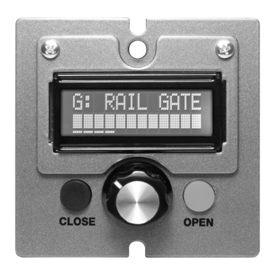
VGG operator's control panel shown actual Size
Other manuals available for the VGC are:
Page 1
VGC Gate Control
Advertisement
Table of Contents

Related Manuals for Schlagel VGC-V2

Summary of Contents for Schlagel VGC-V2
- Page 1 SCHLAGEL, INC. VGC Gate Control VGC-V2 Operating, Customizing And Troubleshooting PATENT PENDING VGG operator’s control panel shown actual Size Other manuals available for the VGC are: VGC Pre-Installation Manual An overview of the VGC components, tips and suggestions for electricians, millwrights and project coordinators.
- Page 2 SCHLAGEL, INC. VGC CONTROL LAYOUT The diagram above shows the function of the controls and the meaning of the text shown in the LCD display. LCD information screen. The display above shows the potentiometer set to approximately 60% and the gate fully closed.
- Page 3 SCHLAGEL, INC. OPERATING THE GATE When the gate is closed, the potentiometer position may be changed but the gate will not move. Once the OPEN button is pressed, the LED will turn red and the gate will open to the potentiometer setting. The gate position indicator blocks will retract to the right as the gate opens, to meet the position of the potentiometer.
- Page 4 SCHLAGEL, INC. CONTROL MENU A menu function on the display allows access to certain functions that perform maintenance, gate operational information and troubleshooting help. To access the menu, close the gate, Press and hold both the CLOSE and OPEN buttons. After 2 seconds the top line of the display will show ‘CONTROL MENU’.
- Page 5 SCHLAGEL, INC. TROUBLESHOOTING A VGC system consists of the VGC Operator Control, a motor power module and a barrier relay. These may be located in diverse areas of the facility. Determining the cause of the problem may require attention to any or all of these areas. The two most common problems are the loss or interruption of power or a mechanical problem at the gate.
- Page 6 SCHLAGEL, INC. RELAY MODE OPERATION (VGC-V2) VGC Relay Mode is used when opening and closing of the gate is performed by an external users relay and the open position is determined by the setting of the VGC control potentiometer. A pair of wires is run from terminals 1 and 5 of the 6 position screw terminal on the VGC control to the N.O.
- Page 7 SCHLAGEL, INC. NETWORK OPERATION Network interfacing for PLC control of the VGC gate is covered in other manuals as referenced on the front cover of this manual. The intent of this section is only to cover the influence of the PLC on the VGC Control from the gate operator’s standpoint.
- Page 8 SCHLAGEL, INC. VGC Specifications VGC Drive Components Motor .5 HP, 1750 RPM, 220 Volt 3 Phase 56 C-Face Gear Reducer 100:1 Worm gear, 1” dia. adjustable clutch driven shaft Inverter input 120 Volt, single phase. Full load current draw 9.6 Amp...
Need help?
Do you have a question about the VGC-V2 and is the answer not in the manual?
Questions and answers