Table of Contents
Advertisement
Quick Links
VISION.NET GATEWAY
SERIES
This document provides basic setup instructions and safety warnings for the following product(s):
65710
65730
INSTALLATION AND SETUP
POWER REQUIREMENTS
Vision.Net Gateway may be powered via either a Power over Ethernet (PoE) supply or from an external DC pow-
er supply connected via a set of screw terminals.
NOTE: DC and PoE power connections will not operate as a redundant power solution.
A CR1225 backup battery (pre-installed) is used for the real-time clock. External modules are powered from the
Gateway module through the DIN rail bus system, and do not require their own power supply.
The Gateway draws up to 40W of power, depending on the confi guration of modules added. For PoE supplies it
is best to use an 803.2bt class7-8 high power source, however in some circumstances, it may be powered from
an 803.2af PoE+ supply. Consult the table below for further information to select the right options.
COMBINATION
Gateway standalone
Gateway + 1 VN
MOUNTING / INSTALLATION
WARNING! Do not power the system until all modules are placed and
connected as described in the steps below.
To mount Vision.Net Gateway and other modules:
Step 1.
Unpack module(s), taking precautions against ESD.
Step 2.
Place the DIN rail bus connector into the DIN rail.
Step 3.
Mount Vision.net Gateway module on DIN rail, taking care to ori-
ent the modules as shown. Take special care aligning, to prevent
bending the pins
•
•
Step 4.
If required, install DIN rail clamps (not supplied) as
necessary.
To remove modules from DIN rail:
Step 1.
Slide any modules apart
Step 2.
Insert fl at head screw driver against the tabs to
release. The DIN rail bus may; in some circum-
stances, remain attached to the rail and can be
removed by releasing the small clips, if required.
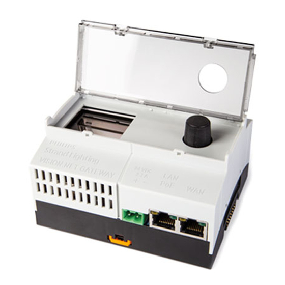
65710
Vision.Net Gateway
Vision.Net Interface Gateway Module
PoE REQUIREMENTS
PoE PSE TYPE
802.3af
802.3bt class 5 or higher
If used, mount accessory modules close to Vision.Net Gate-
way module to ensure good contact
Place end-caps on the DIN rail bus to prevent
dirt contamination on the pins
DESCRIPTION
12W @ the gateway
40W @ the gateway
VISION.NET GATEWAY
W W W. S T R A N D L I G H T I N G .C O M
1
QUICK START GUIDE
SERIAL
USB
–
+
–
+
–
VISION.NET INTERFACE
GATEWAY MODULE
24 VDC
LAN
2.7 A
+
−
PoE
WAN
+
–
+
D
D
Advertisement
Table of Contents

Subscribe to Our Youtube Channel
Related Manuals for Strand VISION.NET Series


Summary of Contents for Strand VISION.NET Series
- Page 1 VISION.NET GATEWAY SERIES QUICK START GUIDE This document provides basic setup instructions and safety warnings for the following product(s): 65710 Vision.Net Gateway 65730 Vision.Net Interface Gateway Module INSTALLATION AND SETUP POWER REQUIREMENTS Vision.Net Gateway may be powered via either a Power over Ethernet (PoE) supply or from an external DC pow- er supply connected via a set of screw terminals.
- Page 2 LIMITED 2-YEAR WARRANTY WARNING: You must have access to a main circuit breaker or other Strand off ers a two-year limited warranty on its control products against power disconnect device before installing any wiring. Be sure that power defects in materials or workmanship from the date of delivery. A copy of is disconnected by removing fuses or turning the main circuit breaker off Strand two-year limited warranty containing specifi...
Need help?
Do you have a question about the VISION.NET Series and is the answer not in the manual?
Questions and answers