
Related Manuals for Thermo King Trailer Edition Heat King 450 Series


Summary of Contents for Thermo King Trailer Edition Heat King 450 Series
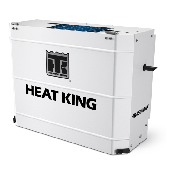
- Page 1 Installation Manual Trailer Edition Heat King 450 Series HK450, HK450 HO and HK450 MAX Diesel Heating Units Revision 1 TK-56118-6-IM May 2015...
- Page 3 Installation Manual Trailer Edition Heat King 450 Series HK450, HK450 HO and HK450 MAX Diesel Heating Units TK 56118-6-IM (Rev. 1, 05/15) Copyright© 2015 Thermo King Corp., Minneapolis, MN, U.S.A. Printed in U.S.A.
- Page 4 Release History Released 05/15 Rev. 1 05/15 Page10: Updated unit weights, pages 18-19: Added drain hose installation instructions (HK450 MAX only).
-
Page 5: Introduction
Introduction This installation manual was written to assist with the installation of the Thermo King Heat King 450 Series transport heaters onto trailers or intermodal containers specifically designed and built for these applications. Separate installation instructions for the various fuel tanks and factory options available for the HK unit are located at Thermo King iService or Thermoking.com. -
Page 6: Table Of Contents
Table of Contents Introduction ..........3 Battery Selection Guide . -
Page 7: Safety Precautions
Safety Precautions symbol appears next to a point that is particularly important: DANGER: Addresses a circumstance that, if encountered, will lead to death or serious injury WARNING: Addresses a circumstance that, if encountered, might lead to death or serious injury. CAUTION: Addresses a circumstance that, if encountered, may cause damage to equipment or minor injury. - Page 8 Battery terminals grounding against metal could CAUTION: Do not connect other manufacturer’s equipment or cause the battery to explode. accessories to the Thermo King unit. This could result in severe damage to equipment and void the warranty!
-
Page 9: Required Tools
Required Tools 1. Safety Glasses 2. Drill 3. Drill Bits 4. Tape Measure 5. Mechanics Tools 6. Lifting Device 7. Two Forged Eyebolts (1/2-13 UNC) 8. Work Platform (Recommended) 9. Torque Wrench NOTE: Equipment such as torque wrenches should be in good working condition and routinely calibrated to assure accurate readings. -
Page 10: Installation Components
Installation Components HARDWARE KIT FUEL LINE KIT FUEL PUMP KIT Clamps Hose 1/4 OD x 40 ft. Fuel Pump Bandwraps Hose 3/8 OD x 40 ft. Hose Fitting 3/8'' Screw 1/4-20 SS Eyelet fitting 1/4'' Pump Bracket Nut 1/4-20 SS Eyelet Fitting 3/8'' Harness Nut 1/2-13... - Page 11 BLANK PAGE...
-
Page 12: Trailer / Container Requirements
Trailer / Container Requirements Heat King 450 Series Units Optional Front Wall Mounted Fuel Tank DANGER: The front wall of the trailer or container must be DANGER: The front wall of the trailer or container must be structurally strong enough to support the weight of a Heat structurally strong enough to support the weight of the King 450 series unit! Heat King 450 series unit, the 65 gallon fuel tank and fuel! - Page 13 Trailer / Container Requirements...
-
Page 14: Mounting Bolt Specifications And Installation Requirements
Mounting Bolt Specifications and Installation Requirements Mounting Bolts Specifications Mounting Bolt Installation Requirements DANGER: The use of mounting bolts other than those DANGER: Four mounting bolts must be installed to properly specified could result in severe damage to equipment, void secure the unit to the trailer front wall! Failure to do so could the warranty or cause personal injury or death! result in severe damage to equipment, void the warranty or... - Page 15 Mounting Bolt Specifications and Installation Requirements...
-
Page 16: Unit Dimensions
Unit Dimensions HK450, HK450 HO and HK450 MAX Units... -
Page 17: Hmi Remote Mount Dimensions
HMI Remote Mount Dimensions... -
Page 18: Battery Selection Guide
CAUTION: Do not connect other manufacturer’s equipment or installer. accessories to the Thermo King unit! This could result in severe damage to equipment and void the warranty! The battery must be suitable for deep cycling, heavy duty and rated with a minimum of 95 amp/hr. -
Page 19: Group 31 Battery Dimensions
Group 31 Battery Dimensions Threaded Stud Connections Lug Connections... -
Page 20: Installing The Unit - Standard Installation
Installing the Unit - Standard Installation Uncrating the Unit Exhaust Drain Tube (HK450 MAX Units Only) 5. From inside the unit, place the supplied hose clamp over the end of the DANGER: Do not use a forklift to install the unit! This could copper exhaust drain tube and slide it up the tube a few inches. - Page 21 Installing the Unit - Standard Installation HK450 MAX Only...
-
Page 22: Installing The Remote Hmi
Installing the Remote HMI NOTE: The installation views shown are for reference only. The actual locations chosen for installing the remote HMI may vary per your specific application and should not interfere with the operation of the trailer or container. Surface Mount Installation Flush Mount Installation NOTE: Installer to provide a recessed pocket in the trailer wall to... - Page 23 Installing the Remote HMI Surface Mount Installation Flush Mount Installation Recessed pocket shown (installer provided)
-
Page 24: Installing The Fuel Pump And Fuel Lines
IMPORTANT: The factory installed fuel tank air vent must be in place for 8 to 12 hours during engine break-in and pre-delivery procedures. and functional for the Thermo King unit’s fuel system to operate correctly and for the fuel tank to remain in compliance with Federal Motor Carrier Safety Administration specifications (title 49, paragraph 393.67). - Page 25 Installing the Fuel Pump and Fuel Lines FOR OPTIONAL UNDER CHASSIS FUEL TANKS FUEL FILTER LOCATED INSIDE UNIT FUEL PUMP LOCATED OUTSIDE TRAILER...
- Page 26 2. Route and attach the fuel pump harness to the fuel pump. IMPORTANT: The factory installed fuel tank air vent must be in place and functional for the Thermo King unit’s fuel system to operate correctly and for the fuel tank to remain in compliance with Federal Motor Carrier Safety Administration specifications (title 49, paragraph 393.67).
- Page 27 Installing the Fuel Pump and Fuel Lines FOR OPTIONAL NOSE MOUNTED L-SHAPED and RECTANGLE SHAPED 65 GALLON FUEL TANKS MOUNT FUEL PUMP INSIDE UNIT FUEL FILTER LOCATED INSIDE UNIT Return Supply...
-
Page 28: Installing The Battery
Installing the Battery Installing the Battery 1. Open unit door to access battery tray. 2. Install battery into tray and secure with hold down bracket, bolts, lock CAUTION: Set all electrical controls to the OFF position before washers and flat washers. connecting the battery to prevent the unit from starting! •... - Page 29 Installing the Battery...
-
Page 30: Service Test Procedure
Service Test Procedure Engine Break-in Test The following procedure is used to run the unit for 10 hours to break-in the diesel engine. 1. Ensure software revision is EB04 or higher. 2. Open PC Monitor - In the menu on the left is a page called “Service Test”... - Page 31 Service Test Procedure...
-
Page 32: System Check List
SYSTEM CHECK LIST All unit mounting hardware torqued to specifications. Battery secured correctly and all connections clean and tight. No air gaps between unit and trailer wall. Remote HMI mounted securely. Drain hose properly routed and secured. Run Pre-Trip Inspection (refer to Operator’s Manual). Fuel tank properly installed. - Page 34 1938. For more information, visit www.thermoking.com or www.tranetechnologies.com Thermo King has a policy of coninuous product and data improvements and reserves the right to change design and specifications without notice. We are committed to using environmentally conscious print practices.
Need help?
Do you have a question about the Trailer Edition Heat King 450 Series and is the answer not in the manual?
Questions and answers