
Related Manuals for SolidHub HE1200/3

Summary of Contents for SolidHub HE1200/3
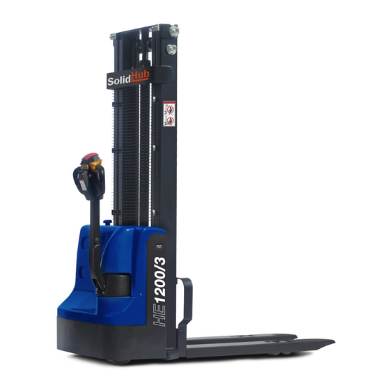
- Page 1 ASSEMBLY & OPERATING INSTRUCTIONS Electric Forklift HE1200/3 Before using, please read this manual and please do not use the Forklift before the installation is complete!
-
Page 2: Table Of Contents
CONTENT GENERAL Foreword Safety Instructions Technical data Overview of the main components Safety devices and warning signs Nameplate Maintenance Operating instructions 7 – 8 Charging and replacing the battery Regular inspections Checklist for maintenance/inspection Troubleshooting PARTS LIST Wheel System Mounting the frame cover Omnidirectional wheel mounting Drive installation 16 –... -
Page 3: General
FOREWORD Congratulations on the purchase of your new electric forklift HE1200/3, this easy to use forklift is made of high quality materials, specially designed for long lasting and reliable operation. For your own safety and for the correct operation of the truck, please read and follow these operating instructions before using the truck. -
Page 4: Technical Data
GENERAL TECHNICAL DATA Modell HSE1200/3 Load capacity 1200 Load centre distance (C) Fork length (L) 1150 Single fork width (e) Total fork width (b5) 550/570/650/695 Lowered fork height (h5) Length fixed forks Length fixed forks single (including the front double frame) Inner width between fixed forks 262/387 Outer width between fixed forks... -
Page 5: Overview Of The Main Components
GENERAL OVERVIEW OF THE MAIN COMPONENTS Name Name The top cover Lift button Emergency stop button Accelerator (butterfly switch) Safety net Horn The mast mounting Safety switch (belly switch) The charger interface The electricity meter Actuator housing Key switch Inner housing The drive wheel The handle arrangement Steering wheel... -
Page 6: Nameplate
GENERAL NAMEPLATE Name, Type Configuration Number Rated Capacity (kg) Max Lift Height Rated Voltage Serial Number Total Weight Total Weight (without battery) (kg) Battery Weight maximum (kg) Battery Weight minimum (kg) Number of Manufacture License MAINTENANCE HYDRAULIC OIL Please check the oil level every six months. The oil should be hydraulic oil: ISO VG32, its viscosity should be 32cSt at 40°C, the total volume is about 4.0 litres. -
Page 7: Operating Instructions
GENERAL OPERATING INSTRUCTIONS When operating this truck, please observe the warning and safety instructions. Make sure that you always look in the direction of travel and that no goods or objects obstruct or restrict your view. Make sure that the goods are placed stable and safe for transport in the middle of the fork. To start, turn the key clockwise, position „On“... - Page 8 GENERAL CONTROL SYSTEM Start the truck, bring the tiller to an inclined position („F“). Operate the direction lever on the tiller (12): Forward „V“ or Reverse „R“. By carefully moving the direction lever, you control the speed until the desired speed is reached. Position the directional lever in the centre to slow the truck down to a complete stop/parking position.
-
Page 9: Charging And Replacing The Battery
GENERAL CHARGING AND REPLACING THE BATTERY • Only qualified personnel should repair or recharge the battery. Please be sure to follow the operating instructions. • These batteries are maintenance-free and must not be refilled with water. • Battery recycling must comply with state laws and regulations. Please comply with these regulations. •... -
Page 10: Regular Inspections
GENERAL REGULAR INSPECTIONS Only qualified and trained personnel may service the truck. Before maintenance, please remove any goods from the forks and move them to the lowest position (parking position of the forks). Only use special cranes/hoists to lift the truck. Be sure to position an additional safety device (such as a jack, wedge or wood) under the truck. -
Page 11: Checklist For Maintenance/Inspection
GENERAL CHECKLIST FOR MAINTENANCE/INSPECTION Monthly intervals Check the hydraulic oil cylinder, the piston is quiet and no fluid is leaking • Check the hydraulic connections and hoses for damage and leaks • Check the hydraulic oil level and top up oil if necessary •... -
Page 12: Troubleshooting
GENERAL TROUBLESHOOTING Problem Reason Solution Overloading of the max. load capacity The maximum load capacity is indicated on the rating plate Battery is too weak Charging the battery The forks cannot be The fuse is out Check and possibly replace the fuse lifted to the maximum The hydraulic oil is not sufficient Check and if necessary top up the hydraulic oil... -
Page 13: Parts List
PARTS LIST WHEEL SYSTEM Code No. Name Quantity CLJ1030.01.01 Steel frame GB/T 879.1-2000 Elastic cylindrical pin ø 5× 35 DFL25.1-14D Connection plate CL10-4H Front axle (2) SL20.1-9 Washer GB/T 276-94 Deep groove ball bearing 6204 CL10-5 Small wheel GB/T 70.1-2000 Hexagon socket head cap screws M12×... -
Page 14: Mounting The Frame Cover
PARTS LIST MOUNTING THE FRAME COVER Code No. Name Quantity GB/T 818-2000 Phillips screw M6× 16 SPN10.0-6 Protective cover clip SPN1016.0-4 Protective cover CLJ1030.06-2 Large flat-head Phillips screw CLJ1030.06-4 Cover CLJ1030.06-3 Lower cover plate of the handle +44(0)20 - 78 94 15 16 info @ topregal.com www.topregal.com... -
Page 15: Omnidirectional Wheel Mounting
PARTS LIST OMNIDIRECTIONAL WHEEL MOUNTING Code No. Name Quantity CL10.5.5.1G Welded seam of the flange GB/T 91-2000 Split pin ø 3.2× 45 CL10.5.5-2 Dust cover JB/T 7940.1-1995 Straight hydraulic grease nipples GB/T 301-1995 Pressure ball bearing 51111 GB/T 276-94 Deep groove ball bearing 6205-2Z CL10.5.5-3 Seal... -
Page 16: Drive Installation
PARTS LIST DRIVE INSTALLATION +44(0)20 - 78 94 15 16 info @ topregal.com www.topregal.com... - Page 17 PARTS LIST Code No. Name Quantity GB/T13871-92 Oil seal TCø 42×ø 20× 7 GB/T276-94 Bearing 6004RS GB893.1-86 Locking ring for bore ø 42 ZD-HZDC-310-002 chassis components GB894.1-1986 Ringshield ø 15 ZD-HZDC-320-002 Rotor ZD-HCDC-340-001 Brush-shaped yoke part GB/T276-94 Bearing 6201RS GB/T70.1-2000 hexagon socket head screw M5×...
-
Page 18: Handle Assembly
PARTS LIST HANDLE ASSEMBLY Code No. Name Quantity TY-01.20 Handle CLJ1030.01.02.01 Grip lever CS1232.8-1 Crash Roll GB/T 70.1-2000 Hexagon socket head cap screws M8× 35 SL13.03-09 Sleeve CJF17-05PA Proximity switch GB/T 93-1987 Spring washer ø 3 GB/T 70.1-2000 Hexagon socket screws M3×... -
Page 19: Hydraulic System
PARTS LIST HYDRAULIC SYSTEM Code No. Name Quantity CLJ1030.05 Oil cylinder module GB982-77 Seal ø 18 CLJ1030.04-1 Rubber hose SPN10.8-6 Oil connection CLJ1030.01.03.03 Aggregate 24V/2.2KW CL10.4-3H 90° connection › Free shipping ( Germany ) › Available immediately › 1 – 5 years guarantee ›... -
Page 20: Electrical Assembly
PARTS LIST ELECTRICAL ASSEMBLY Code No. Name Quantity GB/T 70.1-2000 Hexagon socket head cap screws M3× 20 TY-01.2 Charging socket TY-01.18 Horn DC24-ø125 GB/T 95-2002 Flat washer ø 8 GB/T 93-1987 Spring washer ø 8 GB/T 70.1-2000 Hexagon socket head cap screws M8×... -
Page 21: Mounting The Fork
PARTS LIST FORK Code No. Name Quantity CLJ1030.03.01 Pallet frame (welded) GB/T 276-94 Deep groove ball bearing 6205 SPN10.3-1 Pallet frame roller wheel GB 893.1-86 Locking ring for bore ø 52 GB 894.1-86 Locking ring for shaft ø 25 SPN10.3-3 Lateral pressure pad GB/T 77-2000 Hexagon socket set screw with flat point... -
Page 22: Lifting System
PARTS LIST LIFTING SYSTEM +44(0)20 - 78 94 15 16 info @ topregal.com www.topregal.com... - Page 23 PARTS LIST Code No. Name Quantity GB 894.1-86 Locking ring for shaft ø 20 GB 893.1-86 Locking ring for bore ø 47 GB/T 276-94 Deep groove ball bearing 6204 SPN10.2-5 Sprocket GB/T 70.1-2000 Hexagon socket head cap screws M8× 16 SPN10.2-1 Inner frame roller wheel GB/T 276-94...
- Page 24 TOPREGAL GmbH, Industriestrasse 3, 70794 Filderstadt, Germany Telephone +49 (0)7158-9181500 Email info @ topregal.com, Website www.topregal.com...
Need help?
Do you have a question about the HE1200/3 and is the answer not in the manual?
Questions and answers
My HE-3 will not move on my concrete pole barn floor or outside pavement, is there a way to adjust the drive wheel so it contacts the surface better ?