Table of Contents
Advertisement
Quick Links
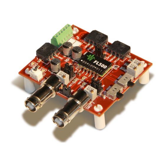
DATASHEET AND OPERATING GUIDE
EASY SETUP SAVES YOU TIME
The FL591FL allows you to quickly and easily prototype your
laser diode driver system using our popular FL500 laser
diode driver chip.
The FL591FL can be configured to drive a single 500 mA
output, or two 250 mA independent outputs by setting
onboard jumpers. The drivers operate in Constant Current
or Constant Power modes.
Onboard current setpoint and limit trimpots mean no external
electronics are required to operate the drivers. Simply
connect the power supply and laser diodes, and you're ready
to go.
CONTENTS
406-587-4910
www.teamWavelength.com
FEATURES AND BENEFITS
• Accurately and efficiently characterize the FL500
in your application environment
• Includes FL500 Laser Driver chip already installed
• Utilizes all the safety features of the FL500
» Adjustable current limits
» Slow-start laser diode protection
» Brownout protection
• Onboard trimpots adjust output current and
current limits
• Drive two independent 250 mA channels or a
single 500 mA output
• Switches set the operating mode to Constant
Current or Constant Power
• Operates Type A and Type B Laser Diodes
• Output Enable switch, LED status indicators
• Power and Output cables included
ACCURATELY PROTOTYPE YOUR
LASER CONTROL SYSTEM
The FL591FL features low-noise electronics and low
quiescent current, and the feedback and monitor signals
allow you to accurately characterize your laser controller.
You can transfer the FL500 prototype configuration directly
to your custom laser control system with no surprises.
The FL500 is commonly used in hand-held, portable, and
space constrained applications. The small size and light
weight makes the FL500 ideal for airborne applications,
and the dual-channel output is perfect for sighting-and-
detection applications.
PAGE
ORDERING INFORMATION
2
4
6
7
8
11
12
17
18
Applies to Product Revisions A through C
© February 2017
FL591FL
Laser Diode Driver
PART NO
DESCRIPTION
FL591FL
Evaluation board with FL500
Distributor
info@amstechnologies.com
www.amstechnologies-webshop.com
Advertisement
Table of Contents

Related Manuals for Wavelength Electronics FL591FL


Summary of Contents for Wavelength Electronics FL591FL
-
Page 1: Table Of Contents
The FL591FL can be configured to drive a single 500 mA You can transfer the FL500 prototype configuration directly output, or two 250 mA independent outputs by setting to your custom laser control system with no surprises. -
Page 2: Quick Connect Guide
VSET 1 ]TWO LD2 Output VSET 2 Connector TRIMPOT RPD2 Figure 1 is the top view of the FL591FL, illustrating the ]OFF onboard switches, trimpots, and connectors. INPUT 2 LD1 MODE LD2 MODE LIM 1 LIM 2 When shipped from the factory, the FL591FL is configured to Current Limit operate with two independent 250 mA outputs. - Page 3 FL591FL LASER DIODE DRIVER QUICK CONNECT GUIDE, CONTINUED The FL591FL is compatible with Type A and Type B lasers, but will not drive Type C lasers; see Figure 3. Ty p e C L a s e r D i o d e...
-
Page 4: Pin Descriptions
FL591FL LASER DIODE DRIVER PIN DESCRIPTIONS Table 1. Pin Descriptions and Wire Colors CABLE NAME PIN DESCRIPTION COLOR Connectors LD1, LD2; Cable FL591-00102-A Laser Diode Anode connection. When used in 2x–250 mA mode, LD1 and LD2 are independent and isolated from each other. When used in 500 mA mode, the current is output via connector LD1 only. - Page 5 0.125 A / V MONx and I output on that channel MON1 MON2 When operating the FL591FL as a single channel 500 mA driver, monitor the output current on both I and I . The total output Current Output Monitor, MON1...
-
Page 6: Electrical Specifications
FL591FL LASER DIODE DRIVER ELECTRICAL SPECIFICATIONS DUAL- SINGLE- ABSOLUTE MAXIMUM RATINGS SYMBOL CHANNEL CHANNEL UNIT NOTE OPERATION OPERATION Supply Voltage 3 to 9 Max LD Output Current (2x) 250 (1x) 500 Laser Driver Internal Power Dissipation 1 W per channel 2 W total = 25ºC... -
Page 7: Safety Information
INTERNAL POWER DISSIPATION LIMITS dual outputs up to 250 mA each. Before attempting to operate the FL591FL, it is imperative When operating with two separate outputs, the FL591FL can that you first determine that the FL500 will operate within the be configured to use a single setpoint to drive both outputs Safe Operating Area (SOA). -
Page 8: Operating Instructions
Setpoint signals are separated with simple precautions. * When JP1 is set to position ONE, the FL591FL references Enter the search phrase “ESD Precautions for Handling the setpoint signal on Input 1. Any setpoint signal on Input 2 Electronics”... - Page 9 Connect the DMM to the LIM1 testpoint and the GND SET THE OUTPUT CONFIGURATION JUMPER testpoint, and apply power to the FL591FL. Adjust the LIM1 The Output Configuration Jumper (JP2), located between trimpot until the voltage displayed on the DMM matches the the output connectors, determines whether the outputs are value calculated above.
- Page 10 DMM matches SET1 the value calculated above. Turning the trimpot clockwise When the FL591FL is delivered it is configured to reference increases the output current. only the onboard trimpot setpoint signals. Repeat the process on the second channel if operating in dual-channel mode.
-
Page 11: Troubleshooting
Refer to page 9 for instructions on setting the laser driver current limit. Laser driver is compliance limited Check the laser diode specifications to determine the forward voltage ). Make sure that the FL591FL is not compliance limited. Refer to the Electrical Specifications table on page 6. Laser does not reach desired... -
Page 12: Technical Support Information
The maximum photodiode current input is 1 mA, but the range can be adjusted by changing a resistor on the FL591FL circuit board. The location of the resistors is shown in Figure 7. The default resistor value is 1 kΩ ±1%. - Page 13 FL591FL LASER DIODE DRIVER FL591FL SCHEMATIC, PAGE 1 © 2017 www.teamWavelength.com...
- Page 14 FL591FL LASER DIODE DRIVER FL591FL SCHEMATIC, PAGE 2 © 2017 www.teamWavelength.com...
- Page 15 0.10 Follow these steps to use the SOA Chart to determine if the FL591FL will be operating safely. Refer to the example SOA 0.05 chart in Figure 8. Room temperature SOA charts for the FL591FL are shown in Figure 9 and Figure 10.
- Page 16 Molex 43030-007 3mm Micro-Fit Terminal 18” Long, 22 AWG 1 - DIS 2 - VS 3 - GND OUTPUT CABLE -- FL591-00102-A; TWO INCLUDED WITH FL591FL Molex 43645-0300 Terminal Housing Molex 43030-007 3mm Micro-Fit Terminal 18” Long, 22 AWG 1 - LDA...
-
Page 17: Mechanical Specifications
The FL500 chip is convection reflow process compatible (not vapor phase). [53.333] 2.100 63.50 2.50 .188 4 PLS 18.38 75.53 2.97 11.99 27.10 1.07 15.11 Figure 11. FL591FL Mechanical Dimensions All dims in [mm] inches; Tolerance ±5% © 2017 www.teamWavelength.com... -
Page 18: Certification And Warranty
SAFETY There are no user-serviceable parts inside this product. Return the CERTIFICATION product to Wavelength Electronics for service and repair to ensure that safety features are maintained. Wavelength Electronics, Inc. (Wavelength) certifies that this product met its published specifications at the time of shipment.
Need help?
Do you have a question about the FL591FL and is the answer not in the manual?
Questions and answers