Table of Contents
Advertisement
Quick Links
DATASHEET AND OPERATING GUIDE
Single 500 mA or Dual 250 mA Channel Laser Diode Driver
FLEXIBILITY YOU NEED
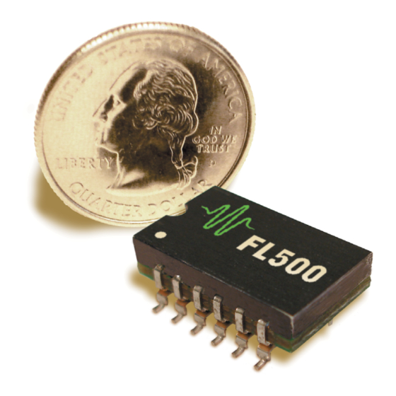
The FL500 Laser Diode Driver comes in a small SMT
package that is reflow process compatible.
The FL500 is ideal for driving low power laser diodes. It
operates from 3 to 12 V, so it is compatible with Li+ battery
operation. This makes it practical for handheld devices.
It can be configured as two totally independent 250 mA
drivers or a single 500 mA driver. It is compatible with
Type A or Type B laser diodes.
CONTENTS
406-587-4910
www.teamWavelength.com
FEATURES
• Small Package: 0.75" x 0.45" x 0.255"
• Low Cost
• Brownout Protection
• 12-Pin, SMT Package, Reflow Compatible
• Slow Start Laser Diode Protection
• Drive Up to 500 mA Output Current
• Can be configured as two 250 mA drivers
• Voltage Controlled Setpoint
• TTL Compatible Shutdown Pin
• Adjustable Current Limit on Evaluation Board
• Adjustable Current Range Output
• 500 kHz sinewave Constant Current Bandwidth
(100 kHz square wave)
EASY INTEGRATION
The FL500 allows for quick and easy operation in Constant
Current (CC) mode. For simple CC mode operation the
only components that are required are a power supply,
an analog control voltage, your laser and optional filtering
circuitry.
For additional features, including current limit and
photodiode feedback for Constant Power operation, use
with the
FL591FL
LEADING EDGE APPLICATIONS
The FL500 is commonly used in hand-held, portable, and
space constrained applications. Small and light weight,
the FL500 is ideal for airborne applications, spectroscopy
systems, and the dual-channel output is perfect for
sighting-and-detection applications.
ORDERING INFORMATION
PAGE
2
PART NO
4
FL500
5
FL591FL
7
8
10
11
12
13
© October 2020
FL500
driver board.
DESCRIPTION
500 mA Laser Diode Driver
500 mA Laser Diode Driver and Board
e
A
Laser Type
Pb
RoHS
B
Laser Type
Advertisement
Table of Contents

Related Manuals for Wavelength Electronics FL500

Summary of Contents for Wavelength Electronics FL500
-
Page 1: Table Of Contents
The FL500 is ideal for driving low power laser diodes. It an analog control voltage, your laser and optional filtering operates from 3 to 12 V, so it is compatible with Li+ battery circuitry. -
Page 2: Quick Connect Guide
Figure 1. FL500 Top View Pin Layout https://www.teamwavelength.com/support/design-tools/soa-ld-calculator/ Figure 3 shows connection diagram for FL500 driver in Figure 1 shows the top view Pin layout of the FL500 driver. single configuration. Figure 2 shows connection diagram for FL500 driver in dual configuration. - Page 3 FL500 LASER DIODE DRIVER QUICK CONNECT GUIDE, CONTINUED The FL500 is compatible with Type A and Type B lasers, but will not drive Type C lasers: see Figure 4. Ty p e C L a s e r D i o d e...
-
Page 4: Pin Description
NAME PIN DESCRIPTION LABEL Power supply input for the FL500’s internal control electronics. Supply range Control Electronics Power input for this pin is +3 to +12 Volts DC. It is compatible with Li+ batteries. Return path for control electronics. Connect ground for V... -
Page 5: Electrical Specifications
Note [1]. Maximum Power Dissipation is 1 Watt per channel. When configured as one driver, maximum power dissipation is 2 W. Note [2]. Constant Power Control is available with the FL591FL diode driver and board as well as the FL500 with the LDTC0520/1020 combination boards. - Page 6 FL500 LASER DIODE DRIVER ELECTRICAL SPECIFICATIONS CONTINUED PARAMETER TEST CONDITIONS UNITS INPUT Offset Voltage, initial, I Pin 2, T = +25ºC, AMBIENT = 0 V Bias Current Pin 2, T = +25ºC, (based on input Res of op amp) AMBIENT...
-
Page 7: Safety Information
The voltage and output current are related by a transfer function that varies by driver To determine if the FL500 driver will be operating in the capacity. The setpoint voltage is adjusted with an external safe range in your application, consult the instructions for input. -
Page 8: Operating Instructions
• Laser Diode together. The transfer function for individual VSETs (1 & 2) • Connecting wires is 0.125 A / V. The FL500 contains circuitry for two 250 mA • Power Supply drivers. Connect one test load (laser diode) to Pins 11 & 12 (LDC1) STEP 1 - CHOOSE ONE OR TWO POWER and Pin 1 (VDD). - Page 9 OPTION 3: OPERATE MULTIPLE FL500S IN PARALLEL Tie LDC1 & LDC2 (Pins 7 & 8, 11 & 12) on each FL500 together and wire the test load to these pins and Pin 1 (VDD). Tie PGND (Pins 9 & 10) together and use to ground .
- Page 10 FL500 LASER DIODE DRIVER DELAYED / SLOW START Once power is applied, current at the attenuated level will flow (~10 µA when configured for 250 mA max). After 100 msec, current will rise to the level dictated by the setpoint voltage at the rate of about 15 mA / msec.
-
Page 11: Additional Technical Information
Line. however we recommend you use the online tools instead. An example SOA calculation for the FL500 for 2 W, 500 mA An example SOA calculation for the FL500 for 1 W, 250 mA for parallel channels operation is shown in Figure 12 where:... -
Page 12: Troubleshooting
Carefully check the wiring diagram according to page 8 and page 9. Driver will not switch on Improperly configured power supply If operating the FL500 with the Evaluation Board, see the FL591FL Datasheet for details regarding power supply. Refer to the RESET/ENABLE control (Pin 3) in Table 1 on... -
Page 13: Mechanical Specifications
FL500 LASER DIODE DRIVER MECHANICAL SPECIFICATIONS FL500 IS REFLOW PROCESS COMPATIBLE. All dimensions are ±5% 0.75” 0.75” [19.1 mm] [19.1 mm] 0.125” 0.047” [3.2 mm] [1.19 mm] 0.100” 0.45” 0.018” [2.5 mm] [11.4 mm] [0.46 mm] 0.085” 0.48” [2.2 mm] [12.2 mm]... -
Page 14: Certification And Warranty
Wavelength. 406-587-4910 (tel) SAFETY 406-587-4911 (fax) There are no user-serviceable parts inside this product. Return the product to Wavelength Electronics for service and repair to ensure Sales & Tech Support that safety features are maintained. sales@teamwavelength.com techsupport@teamwavelength.com ©...
Need help?
Do you have a question about the FL500 and is the answer not in the manual?
Questions and answers