Table of Contents
Advertisement
Quick Links
Advertisement
Table of Contents

Related Manuals for vds MARQUEE ACON Ultra Camera Kit

Summary of Contents for vds MARQUEE ACON Ultra Camera Kit
- Page 1 Artisan Technology Group is your source for quality new and certified-used/pre-owned equipment SERVICE CENTER REPAIRS WE BUY USED EQUIPMENT • FAST SHIPPING AND DELIVERY Experienced engineers and technicians on staff Sell your excess, underutilized, and idle used equipment at our full-service, in-house repair center We also offer credit for buy-backs and trade-ins •...
- Page 2 ® MARQUEE ACON Ultra Operation & Maintenance Manual VDCDS Doc : 79024-01 Revision 2.0.2– 07/30/2007...
-
Page 6: Table Of Contents
Table of Contents Section 1 ACON Ultra Camera/Server Installation Instructions .............. 1-1 Contents of the MARQUEE™ ACON Ultra Kits ..................1-1 1.1.1 ACON Ultra Camera Kit (VDCDS P/N 69871-01)................ 1-1 1.1.2 ACON Ultra 2 Camera Kit (VDCDS P/N 69871-05)..............1-1 1.1.3 ACON Ultra Server Kit (VDCDS P/N 69871-02/ -06) .............. - Page 7 Marquee ACON Ultra Installation/Operation Guide 1-2. ACON U ..................1-1 ABLE LTRA AMERA ONTENTS 1-3. ACON U ......................1-1 ABLE ERVER LTRA 1-4. FLOLS B ......................... 1-2 ABLE RACKET 1-5. ACON U P/N ................1-2 ABLE LTRA EORDER EPLACEMENT Supplement History •...
-
Page 8: Acon Ultra Camera/Server Installation Instructions
Marquee ACON Ultra Installation/Operation Guide Section 1 ACON Ultra Camera/Server Installation Instructions Please read these instructions in its entirety prior to installation Projector software version 6.0 or greater required to operate ACON Ultra Contents of the MARQUEE™ ACON Ultra Kits 1.1.1 ACON Ultra Camera Kit (VDCDS P/N 69871-01) Item... -
Page 9: Contents Of Flols Bracket Kit (Vdcds P/N 69871-10)
Marquee ACON Ultra Installation/Operation Guide 1.1.4 Contents of FLOLS Bracket Kit (VDCDS P/N 69871-10) Item Part Description ACON ULTRA SHIPPING BOX, CAMERA SCR, 1/4-20 X 1/2"L, SHCS, SS SCR, 1/4-20 X 1 3/4"L,SHCS, SS SCR, #8-32 X 5/8"L SHCS S.S. WSHR, #8 FLT, SS WSHR, 1/4", FLT, SS, .035 THK ACON ULTRA... -
Page 10: Figure 1-1. Camera Factory Settings
Marquee ACON Ultra Installation/Operation Guide On the backside of each camera are several DIP switches and controls. If these settings are not properly set, the camera will not properly operate. Verify the following factory settings; See Figure 1-1. 1. On the 10-postion DIP switch, verify that switches 8 (FR/FL) and 9 (γ) are in the “on”... -
Page 11: Mounting The Camera Assembly
Marquee ACON Ultra Installation/Operation Guide Figure 1-2. Camera Address Switches (Camera ID). 1.3.2 Mounting the Camera Assembly There are two camera configurations, one mounted on the front panel (Section 1.4.3.1) and the other mounted on the top bracket (Section 1.4.3.2). 1.3.2.1 Mounting the Camera Assembly on the Front Panel CAUTION: DO NOT hold the ACON Ultra assembly by the lens or camera. - Page 12 Marquee ACON Ultra Installation/Operation Guide 4-places Backside Refer to Table 1-1 for 4-places Item number references UPGRADED FRONT COVER SUPPLIED SEPARATELY 4-places Front side Figure 1-3 AU Camera Mounting Manufacturer/Serial Number Label Location Do not hold the ACON Ultra assembly by the lens or camera. Use only the hardware supplied in the kit: Screws that are too short will strip the holes in the camera.
-
Page 13: Figure 1-4. Front Lower Trim Cover Removal
Marquee ACON Ultra Installation/Operation Guide INSTALL SCREW (FOR TOP BRACKET INSTALLATION ONLY) R E M O V E LO WE R T R I M C O V E R RE M O V E L O WE R CO V E R S C R E W (4 pla ce s ) D I S C O N N E C T D B C O NN E C T O R F R O M L O WE R T R I M C O V E R Figure 1-4. -
Page 14: Figure 1-5 Top Bracket Installation
Marquee ACON Ultra Installation/Operation Guide 2. Install camera Do not hold the ACON Ultra assembly by the lens or camera. Use only the hardware supplied in the kit: Screws that are too short will strip the holes in the camera. Screws that are too long will short the ACON Ultra power supply. -
Page 15: Camera Dimensions, Components And Inputs/Outputs
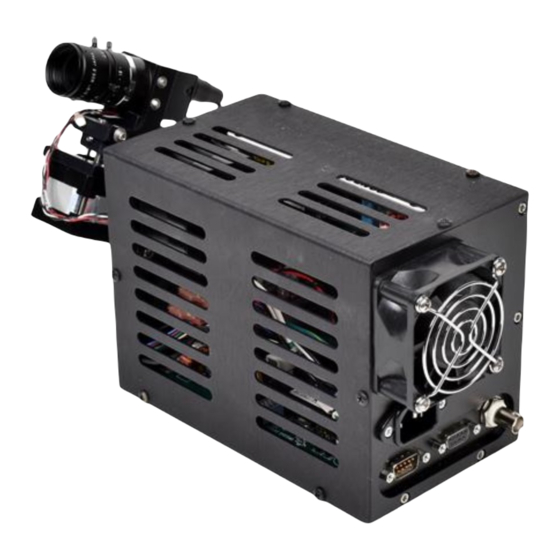
Marquee ACON Ultra Installation/Operation Guide 1.3.3 Camera Dimensions, Components and Inputs/Outputs Motion Control Board (MCB) Camera Power Supply Camera Motor (Tilt) VIDEO “Out” Camera Motor (Pan) CAUTION Hot Surface RS-232 “In” AC “Out” to projector RS-232 “Out” AC “IN” Figure 1-6. Camera Dimensions, Components, Inputs and Outputs Video Out Tilt Motor Camera... -
Page 16: Server Connections And Operations
Marquee ACON Ultra Installation/Operation Guide Figure 1-7. ACON Ultra 2 Camera Components, Inputs and Outputs Server Connections and Operations 1.4.1 Server Rear Panel Connections / ID On the rear of the AU Server is located all the interfacing boards and connectors of the system. The Video Input Card(s) are used to interface the individual AU Cameras’... -
Page 17: Acon Ultra License Key Installation
Marquee ACON Ultra Installation/Operation Guide 1.4.2 ACON Ultra License Key Installation AU operation requires that a valid, activated hardware license key be installed on the server. The license key contains the ACON Ultra options that have been added to the system. If the system has not been shipped with this key, the following, steps must be followed to install. -
Page 18: Figure 1-10. Video Boards Inputs. Video Id (Board, Channel)
Marquee ACON Ultra Installation/Operation Guide Figure 1-10. Video Boards Inputs. Video ID (Board, Channel) Figure 1-12 illustrates a 9-projector installation. The projector IDs’ are 1 through 9. The RS232 Serial port 1 from the AU Server is routed to Projector 001 (1). The RS232 loop-thru on Projector 1 is then routed to Projector 002 (2) then looped to Projector 003 (3). -
Page 20: Figure 1-12. Server Serial Communication And Video Routing Example
Marquee ACON Ultra Installation/Operation Guide AU Server RS232 Projector COM 1 COM 2 RS232 Projector Cable, DB37 to 4 Each DB9 (VDCDS P/N 81749-02) COM 6 RS232 Camera COM 3 COM 5 Projector ID: 001 Projector ID: 007 Projector ID: 004 Camera ID: 1 Camera ID: 7 Camera ID: 4... - Page 21 Marquee ACON Ultra Installation/Operation Guide This page intentionally left blank 1-12 ACON Ultra Camera/Server Installation Instructions...
-
Page 24: Au User Controls, Settings And Operation
Section 2 AU User Controls, Settings and Operation Introduction ACON Ultra (AU) utilizes a non-calibrated grayscale camera to correct the geometry and convergence of a Marquee family projector. The system functions within several assumptions. The projector and the camera are both firmly mounted and do not physically move relative to the projection facet. The AU camera has the capability to index the camera position such that the entire projection facet is visible to the camera. -
Page 25: Drop Down Menus
Projector(s) Selection/Status Window AU Operation Status Window 2.2.1.1 Main Screen: From the Main Screen level, you can select all functions of the AU operation. NOTE: No functions can be performed until one projector or a combination of projectors is selected in the system. - Page 26 Marquee ACON Ultra Installation/Operation Guide Librarian: Future Feature • Librarian, Upload: Future Feature • Librarian, Download: Future Feature • Registry Backup • Registry Restore • Registry Refresh • Exit: Exit the AU program. • NOTE: Once the AU program is closed, all remote control functions within the projector’s menu structure relating to the AU operations are disabled.
- Page 27 Marquee ACON Ultra Installation/Operation Guide Power On: power the projector(s) on. • Power Off: power the projector(s) off • Standby On: This explicit command places the selected projector or projectors in the “Standby” or • “video mute” mode. Standby Off: This explicit command takes the projector(s) out of standby or video mute mode •...
- Page 28 Marquee ACON Ultra Installation/Operation Guide Projector PC’s Serial Port; use this function to indicate and sync the communication port that the projector is using. PC’s Baud Rate; Ensure that 9600 baud is selected. Camera PC’s Serial Port; use this function to indicate and sync the communication port that the camera is using.
- Page 29 Marquee ACON Ultra Installation/Operation Guide Geometry and Convergence: Calibrates both the geometry and convergence test points and scaling. Geometry All: Calibrates the center and screen geometry test points and scaling. Geometry Center: Calibrates only the center geometry test points and scaling. Geometry Screen: Calibrates only the screen geometry test points and scaling.
-
Page 30: Additional Menus And Dialogs
Marquee ACON Ultra Installation/Operation Guide issued a Motor On command or an Initialize AU Hardware command and does not plan to perform another AU operation, this command should be used. NOTE: If the camera motor has been explicitly turned “off”, any one of the AU operations, geometry or convergence functions will automatically power the motor back on. - Page 31 Marquee ACON Ultra Installation/Operation Guide AU User Controls, Settings and Operation...
- Page 32 Marquee ACON Ultra Installation/Operation Guide 2.2.3.1.1 Dependencies The setup tasks in the flow chart show which tasks must be completed before others can be started. If there are arrows from a task pointing to a task on a higher row, the lower task must be completed before the upper row task can be started.
- Page 33 Marquee ACON Ultra Installation/Operation Guide 2.2.3.1.2 Edit Setup Flags Utilizing the automated operations controlled via the Setup Tasks pane in this window, the Setup Flags are updated and progress is shown. In some instances, the user may wish to manually alter the state of the flags.
- Page 34 Marquee ACON Ultra Installation/Operation Guide 2.2.3.1.4 Projector Mapping The Projector Mapping dialog allows a manual mapping of the physical relationship of the projectors in the system. Choose “Overlap” for channels whose projections are intersecting or overlapped. Choose “Adjacent” for channels whose projections are adjacent, but do not intersect or overlap. Choose “Disjoint”...
- Page 35 Marquee ACON Ultra Installation/Operation Guide 2.2.3.1.5 ScreenGeom editor The screen geometry script editor is used to define the shape of the screen, edge by edge, so that the automated routine can correctly position the Screen Geometry test point set. Each corner of the screen is defined by selecting a valid intersection near the actual screen corner.
- Page 36 Marquee ACON Ultra Installation/Operation Guide 3. Click on the Store button to save the information. 2.2.3.1.6 Calculate Primary Relationships The Primary Relationships operation is to be completed once per projector channel. All channels may perform this operation simultaneously. After pressing the button, the Projector Selection Dialog appears, prompting selection of the channels on which the Primary Relationships operation is to be performed.
- Page 37 Marquee ACON Ultra Installation/Operation Guide Steps to follow: 1. Choose a zone (Center, North, or West) from the Zone list. The projector will display a rectangular cursor in the corresponding zone. 2. Change the camera field of view to center the intersection closest to the displayed cursor. If “Motor Movement”...
- Page 38 Marquee ACON Ultra Installation/Operation Guide NOTE: If projectors are overlapped, they will be scheduled to operate sequentially to prevent interference. 2.2.3.1.8 Calibration The Calibration routines may be run only after the initial TP setup has been completed for the test point set.
- Page 39 Marquee ACON Ultra Installation/Operation Guide Play: This button is included for future releases. • Forward: This button is included for future releases. • Pause: This button will cause the process to wait until the current batch of projectors finish their •...
- Page 40 Marquee ACON Ultra Installation/Operation Guide Graph: This button will display the Graph Page dialog. • 2.2.3.1.1.1 Graph Page Dialog The graph dialog displays all of the active test points in the current set. Clicking on a test point selects that test point for editing. Test points are shown in different colors to indicate the error state of each test point.
- Page 41 Marquee ACON Ultra Installation/Operation Guide Red Circle: Test point with an error. • Green Circle: Test point that is OK. • Blue Circle: Test point is unused. • Yellow Circle: Current selection. • White Ring: Indicates multiple test points at the same location. •...
- Page 42 Marquee ACON Ultra Installation/Operation Guide 2.2.3.1.2.1 Basic Motor Dialog This dialog, which allows the user to position the camera field of view for the active test point, is used inside all Maintenance Dialogs. As shown below there are several functions associated with this dialog. Refer to the illustration for additional information.
- Page 43 Marquee ACON Ultra Installation/Operation Guide the image and move the motor to position that intersection at the center of the screen. 2.2.3.1.2.2 Visibility Dialog The Visibility Dialog allows the user to set the image quality (or visibility settings) without affecting the actual user’s settings.
- Page 44 Marquee ACON Ultra Installation/Operation Guide 2.2.3.1.2.3 Auto Gain Control Dialog Controlled Parameters establish nested loops, or ranges, over which AGC searches to obtain optimum visibility settings. It enables the desired parameters and selects the range of the search. Ranges are inclusive, so in the above dialog, Contrast would have two steps during a search: 40 and 50.
- Page 45 Marquee ACON Ultra Installation/Operation Guide AGC routines contain 4 pre-defined sets of parameters Level 1 – Level 4. Level 1 allows the least complex search pattern. The complexity of the search increases with each higher level. Any user defined settings are placed in the custom level. Default Complexity Level and Controlled Parameters are set for each projector with the “Base AGC”...
-
Page 46: Au Remote Control Operation
Marquee ACON Ultra Installation/Operation Guide Error Flag: This flag is shown red if the selected test point is in error, or green for a good test point. • OK: This button will “press” Apply and close the window. • Cancel: This button cancels any changes since the last time Apply was pressed. •... -
Page 47: The Setup And Calibration Process
Marquee ACON Ultra Installation/Operation Guide the above selections, both the geometry and convergence functions will be performed. The Setup and Calibration Process 2.3.1 Setup and Calibration Overview Before the ACON Ultra system can be used to perform its correction operations, the system must be aligned and configured to work properly with the installed hardware system (including the projector, camera mounting, projection facet, etc). -
Page 48: Primary Relationships
Marquee ACON Ultra Installation/Operation Guide NOTE: The initial projector Alignment is accomplished in the methods detailed under the installation’s standard operating procedures. If a customized method is unavailable, a guide to setting up projector geometry is contained within the projector’s user manual. Additionally, it is important that the AU camera is suitably mounted and cables appropriately connected to allow communication with each of the projectors and each of the cameras in the complete system. - Page 49 Marquee ACON Ultra Installation/Operation Guide corrected. For example, a screen that is not rectangular will conceal some convergence zones from view. However, some of these zones may still have a small area of the screen that would be affected by a drift or change. If the test pattern being used does not provide an intersection within this small area of the screen affected, the resolution of the corrections is too large, and the corrections from ACON Ultra are not optimum (if they are able to be performed at all).
-
Page 50: Test Point Locations
Marquee ACON Ultra Installation/Operation Guide sampled measurement during an ACON Ultra operation, is determined by the current placement of Zone42 of the Convergence Test Point Set. Further, the “Visibility Settings” used during the measurement are the current settings for Convergence Zone42. If the ACON Ultra software is having problems correctly identifying a test pattern, the settings for Zone42 should be adjusted. - Page 51 Marquee ACON Ultra Installation/Operation Guide When AU takes a measurement from any test point, the camera is indexed to the established coordinates, and a routine determines the intersection that is closest to the center of the captured camera field of view. If the measurement type is an Intersection type, the X and Y position of this intersection is the reported measure.
- Page 52 Marquee ACON Ultra Installation/Operation Guide 2.3.4.3 The Screen Geometry test point set Facet edge The Screen Geometry test point set is arranged at regular intervals around the outside edges of the screen. The geometries that are controlled during this pass affect the entire screen, so the density of the test points should be sufficient to observe any shifts in these geometries.
- Page 53 Marquee ACON Ultra Installation/Operation Guide The number of test points chosen for the Screen Geometry test point set affects several operational characteristics. If the number of test points is insufficient, the Calibration routines will not have enough information to be able to recognize some or all of the projector geometries to be corrected. After completion of the calibration routine, AU will issue any warnings concerning invalid geometry models.
-
Page 54: Calibration
Marquee ACON Ultra Installation/Operation Guide misconvergence is visible, use the Motor Control Tab to reposition the camera location until the center intersection shows the most misconvergence. In the corresponding picture, a blue circle is shown around the intersection that should be positioned at the center of the image. NOTE: When Show Misconvergence is checked, the displayed image does not automatically update. - Page 55 Marquee ACON Ultra Installation/Operation Guide wider than that of the projector brightness parameter. When beginning the process of adjusting test point visibility settings, Set the two camera parameters as discussed previously (gain at 100%, offset at 50%) and then set the projector brightness at mid range (total brightness range is 0-255, so midrange is 127).
- Page 56 Marquee ACON Ultra Installation/Operation Guide Step Contrast Gain (R) 1600 1700 (G) 1600 1700 (B) 1600 1700 (R) 1600 1700 (G) 1600 1700 (B) 1600 1700 (R) 1600 1700 (G) 1600 1700 (B) 1600 1700 (R) 1600 1700 (G) 1600 1700 (B) 1600 1700...
- Page 57 Marquee ACON Ultra Installation/Operation Guide that allows a conversion from camera pixels, to convergence steps. This is done on a test point by test point basis. If the automated Convergence Calibration routine has been completed and indicates some inadequate results in test points, revisit those test points via the Convergence Maintenance Window and adjust the settings.
-
Page 58: Memorization
Marquee ACON Ultra Installation/Operation Guide 2.3.6 Memorization Once the Calibration operation is successful, the system is ready to memorize the current geometry of the projector. Two sets of data are acquired during memorization. The first is the set of electronic settings which establish the projector’s existing geometry and convergence information. - Page 59 Marquee ACON Ultra Installation/Operation Guide the Geometry operation corrects the projector’s geometry settings that are mainly observed around the edge of the projection (e.g. skew, bow, pincushion, etc). The third pass of Geometry operation uses green convergence to perform a point-to-point correction across the entire screen. While performing the Center (first pass) or Screen (second pass) Geometry corrections, AU first samples all test points in the appropriate set, then calculates which, if any, projector geometry needs modifications.
-
Page 60: Procedure Outlines
Marquee ACON Ultra Installation/Operation Guide 2.3.8 Procedure Outlines 2.3.8.1 AU Initial Setup The following presents an outline of the method for initializing a new AU installation. The outlined method is structured to attempt to minimize the total required setup and configuration time. If this is not a new installation, some of these steps may be skipped or modified as indicated below. - Page 61 Marquee ACON Ultra Installation/Operation Guide NOTE: (s/w 2.0.20060721): When switching to a projector’s relationship mapping page for the first time, some projectors may already appear to be setup because of earlier choices made. The software does not always recognize that a selection has been made even if it is shown. To prevent this, when switching to a projector’s relationship mapping page for the first time, select –...
- Page 62 Marquee ACON Ultra Installation/Operation Guide Move the field of view to the center of the facet. • i. From the zone dropdown selector, select the “Center” zone. ii. Double click on the image to move the camera’s field of view until the rectangular cursor is centered in the image.
- Page 63 Marquee ACON Ultra Installation/Operation Guide test scores are obtained. If necessary, some of the visibility parameters may be manually adjusted, or the complexity level of the AGC operation may be elevated until AGC completes successfully. All scores from a test must be above 50% to achieve a successful completion. NOTE: If manually adjusting the visibility parameters, it is desirable to drive the projector’s contrast and G2 as little as possible.
- Page 64 Marquee ACON Ultra Installation/Operation Guide c. Now, double clicking on the view window in either a clockwise or counter- clockwise direction until you locate another facet corner. Repeat steps b and c until you have chosen a valid intersection in every corner of the facet. (You do not have to return to the original corner, as long as every corner has one test point stored.) NOTE:...
- Page 65 Marquee ACON Ultra Installation/Operation Guide f. If the current visibility settings do not allow the projected intersections to be viewed use the Visibility tab to adjust the visibility settings a) Perform the AGC calibrate routine until acceptable test scores are obtained.
- Page 66 Marquee ACON Ultra Installation/Operation Guide 4) Based on program feedback, revisit the test point settings of each test point which requires further maintenance (consult FMEA worksheet). NOTE: (s/w 2.0.20060721): The Error Flag indicator in the Maintenance Window for both Geometry test point sets does not print an error message in the status region of the window as it does in the Convergence Maintenance window.
- Page 68 Appendix A Firmware Upgrade This section provides instructions for upgrading the projector to include the latest version firmware. Upgrade kits are available from VDCDS. A typical firmware version upgrade requires that IC U35 on the Control Board (the main board of the Control Module) be replaced. Tools &...
- Page 69 Marquee ACON Ultra Installation/Operation Guide IMPORTANT ! : Many ICs on the Control PCB appear similar. Make sure you properly identify the IC before replacing it. IMPORTANT ! : Use a PLCC 20-128 pin extractor when removing U35, DO NOT use a screw driver to remove ICs.
- Page 70 Appendix B ACON Ultra Maintenance ACON Ultra Camera Maintenance The ACON Ultra camera needs little or no maintenance with the exception of periodically cleaning the camera lens. A small amount of dust will not affect the actual operation of the system.
- Page 71 Marquee ACON Ultra Installation/Operation Guide ACON Ultra Diagnostic Report for O&M manual 1. Site Information (person, location, contact info) 2. ACON Ultra version (as appears on splash page, or from About Box) 3. Number of projectors in system 4. Operation (check one) a.
- Page 72 Appendix C Script Files in ACON Ultra Script Files. NOTE: The script files are for information only and require no action on the part of the user. It is sometimes desirable to view one of the test point sets in a tabular format. The Script files provide a mechanism within the AU framework to view this information.
- Page 73 Marquee ACON Ultra Installation/Operation Guide indicates the type of the zone: Static, Used, or Unused. The next column gives the x-y coordinates of the motor position. The region of interest (ROI) Offset provides information that helps AU locate the intersection in question. The Scale Factor is the result of the Scaling calibration routine discussed in the next section.
- Page 74 Marquee ACON Ultra Installation/Operation Guide Test Point name Motor Visibility Settings ScreenTP01Hor 0 MV/ ScreenTP01Ver 0 MV/ ScreenTP02Hor 1900 MV/ ScreenTP02Ver 0 MV/ ScreenTP03Hor 1900 MV/ ScreenTP03Ver 0 MV/ ScreenTP04Hor 1900 MV/ ScreenTP04Ver 0 MV/ ScreenTP05Hor 1900 MV/ 5. Geometry Seed File scripts The Geometry Seed File Definitions script loads important information for the calibration of each $Edge...
- Page 76 Marquee ACON Ultra Installation/Operation Guide Appendix D Subassembly Removal and Installation Caution: This equipment is ESD sensitive. Put on an ESD wrist strap and clip the ground strap to an unpainted spot on the chassis before handling any PCBs. Note: This procedure includes cover removal and installation, and the removal and installation of several subassemblies. It is suggested that you remove the cover, locate the steps covering the removal and installation of the faulty subassembly, replace that subassembly, then replace the cover.
- Page 77 Marquee ACON Ultra Installation/Operation Guide 6. When the drive is in all the way, press the handle down to latch the drive in the bay. Turn the key clock-wise. Apply power to the server and look for a green power indicator light on the lower right.
- Page 78 Marquee ACON Ultra Installation/Operation Guide 11. Remove the support bar and set it aside. 12. To replace the frame grabber PCB in slot number 1: 13. Locate the ribbon cable from the second PCB to the first PCB. Disconnect the cable from the first PCB.
- Page 79 Marquee ACON Ultra Installation/Operation Guide 16. Remove the new PCB 81752-01 (frame grabber) from the package and record its serial number. Install the PCB in the first slot. 17. Slide the PCB into the slot and press firmly to seat. 18.
- Page 80 Marquee ACON Ultra Installation/Operation Guide 20. To replace the frame grabber PCB in slot number 2: 21. From the second PCB, remove the nuts from BNCs 1 and 3. Keep the nuts for installation. Note: A 14mm or 9/16in deep socket fits in the space available.
- Page 81 Marquee ACON Ultra Installation/Operation Guide 25. Remove the screw securing the PCB in the second slot. 26. Carefully remove the video expansion PCB from the second slot. 27. Remove the new PCB (81753-01) from the package and record its serial number. 28.
- Page 82 Marquee ACON Ultra Installation/Operation Guide 29. Remove the bezel. 30. Ensure that there are shunts on ST5 and ST6. 31. Install PCB in the second slot, press firmly to seat. Install 1 screw and tighten to secure. 32. Install the bezel over the BNCs on the second PCB.
- Page 83 Marquee ACON Ultra Installation/Operation Guide CAUTION: The nuts and BNCs must not be crossthreaded. On the second PCB, install a nut on BNCs 1 and 3, and tighten nuts. Note: A 14mm or 9/16in deep socket fits in the space available. 34.
- Page 84 Marquee ACON Ultra Installation/Operation Guide 37. Locate the ribbon cable on the PCB in the second slot. 38. Connect the ribbon cable to the first PCB, as shown. 39. If the video expansion PCB in slot number 2 is not to be replaced immediately, locate the ribbon cable connector on the PCB in slot number 3.
- Page 85 Marquee ACON Ultra Installation/Operation Guide 41. To replace the frame grabber extension PCB in slot number 3: 42. On the PCB in slot number 3, remove the nuts from BNCs 1 and 3. Keep the nuts for installation. Note: A 14mm or 9/16in deep socket fits in the space available.
- Page 86 Marquee ACON Ultra Installation/Operation Guide 46. Take the second 81753-01 PCB (to be installed in 3 slot) from the package and record its serial number. Remove 2 nuts and the bezel. Disconnect the ribbon cable, shift it to the left and connect it as shown.
- Page 87 Marquee ACON Ultra Installation/Operation Guide 50. Install 3 washers each on BNCs 2 and 4. CAUTION: The nuts and BNCs must not be crossthreaded. Install a nut on BNCs 2 and 4 and tighten nuts. Note: • A 14mm or 9/16in deep socket fits in the space available.
- Page 88 Marquee ACON Ultra Installation/Operation Guide 53. Press firmly to seat. Note: PCB number 1 plugs into PCB number 2. PCB number 3 plugs into PCB number 2. 55. To replace the power supply: 56. Inside the chassis, disconnect power supply (PS) cable from the hard drive.
- Page 89 Marquee ACON Ultra Installation/Operation Guide 57. Disconnect 2 PS cables from the single-board computer (SBC). 58. Disconnect PS cables as shown. 59. From the rear panel, remove 4 screws. Keep screws for installation. Carefully remove the PS from the chassis. D-14 Subassembly Replacement...
- Page 90 Marquee ACON Ultra Installation/Operation Guide 60. Install the new PS in the chassis. Install 4 screws and tighten to secure. 61. Inside the chassis, connect PS cable to the hard drive. 62. Connect 2 PS cables to the SBC. D-15...
- Page 91 Marquee ACON Ultra Installation/Operation Guide 63. Connect PS cables as shown. 64. To close the server after subassembly replacement: 65. Install support bar in the chassis. 66. Install 2 screws to secure. 67. Install top cover. Slide the cover under lip on top. D-16 Subassembly Replacement...
- Page 92 Marquee ACON Ultra Installation/Operation Guide 68. Install 4 cover screws and tighten to secure. End of procedure. D-17...
- Page 93 Artisan Technology Group is your source for quality new and certified-used/pre-owned equipment SERVICE CENTER REPAIRS WE BUY USED EQUIPMENT • FAST SHIPPING AND DELIVERY Experienced engineers and technicians on staff Sell your excess, underutilized, and idle used equipment at our full-service, in-house repair center We also offer credit for buy-backs and trade-ins •...
Need help?
Do you have a question about the MARQUEE ACON Ultra Camera Kit and is the answer not in the manual?
Questions and answers