Advertisement
Quick Links
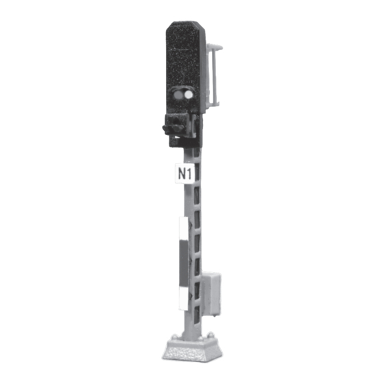
Item No LS4811
Signal Kit
Light Block Signal, 1:220 (Z)
Dieses Produkt ist
D
kein Spielzeug.
Nicht geeignet für
Kinder unter 14
Jahren!
This product is not
GB
a toy.
Not suitable for
children under 14
years!
Ce produit n'est
F
pas un jouet.
Ne convient pas
aux enfants de
moins de 14 ans!
Made for:
Lokshop eK
Froschhöhle 9
D - 76229 Karlsruhe
Tel.: +49721/490350
Fax: +49721/4903520
E-Mail: mail@lokshop.de
10 - 16 V, DC/AC
The following instructions should be
read carefully!
Congratulations!
You have bought a high-quality product, supposed to give pleasure during
assembly and use. Please read these instructions carefully before assemb-
ling or using the product and check if the content of the packaging is com-
plete.
Safety advices
This kit contains small parts which can easily be swallowed by children. Not
suitable for children under 14 years!
The electric and electronic components may only be run with approved
low-voltage transformers. The components are sensitive to heat and may
only be exposed to high temperatures for a short time. Do not "roast"!
A soldering iron develops temperatures up to 400°C. Do not leave it unat-
tended! Keep distance to combustible materials and use a heat-resistant
base-pad for work. Any electrical connection-work may only be done when
disconnected from the main power supply.
All sources of current must be secured against short-cut in order to prevent
fire. Resistors are necessary for regular function. Lamps run without resis-
tors will be destroyed. Resistors may not be covered with insulating materi-
als in order to guarantee sufficient cooling.
Please check at first if the kit is complete. In case of damaged or
missing parts due to the sellers improper packing, please send
back the whole package.
Hp0/Hp1
1
mast, pre-assembled with signal
1
screen, post plate, foundation and
plate for signal number
2
1
circuit board with 2 LED's
�
3
1
back part of mast with basket
4
1
switchbox
Without illustration:
5
1
diode
6
2
resistor
7
1
cable
8
1
shrink-tube, black
9
1
shrink-tube, green
10
1
shrink-tube, red
11
1
labels
The following tools are required:
Small edge cutter
Flat pliers and pointed tweezers
Soldering iron with thin tip, solder (pref. Ø 0,5 mm)
Superglue
Assembly:
For a better control, you can tick each finished work-step in a box at the
left side of the text.
1.
Shorten the cable into 3 pieces of equal length. Uninsulate the ends
of all cables (length: approx. 3 mm) and tin-plate them.
2.
Lead the cables through the mast (1) so that approx. 20 cm of the
cables remain outside at both ends.
3.
Solder one of the cables (7) on the diode (5). The black ring must
tend towards the cable! Insulate the junction with black shrink-tube
(8). Shrink on with hair-drier or hot-air-gun. Attention: the shrink-tube
should me mounted onto the cable before soldering! (Fig. 1)
7
8
4.
The other cables are being soldered on the resistors (6). Insulate the
junctions with the other shrink-tubes (9, 10). Attention: shrink-tubes
should me mounted onto the cables before soldering! (Fig. 2)
7
9
10
Solder the cables on the
5.
circuit-board (2), which is
not yet inserted into the
signal screen according to
Fig. 3. (LED's are placed at
the front side.) Solder only a
short time! Do not 'roast'!
The LEDs and the circuit
board are sensitive to heat.
Use only little solder! Take
care that the fields are not being connected electrically!
If all cables are soldered on correctly, check the function of each
6.
LED before you insert the circuit board into the screen. To do so,
connect each LED with the the alternating voltage output of a
commercially available model-railway transformer. The cable
insulated with black shrink-tube is the common anode ('+').
(Attention: Die LEDs may never be run without resistor and diode!)
Then the circuit board (2) is being inserted into the signal screen.
7.
Gently pull out the cables at the bottom of the mast (be careful!).
Make sure the cables are being pulled through from top to the
bottom.
Content:
3�mm
5
3�mm
6
.
Solder on
cables with
matching colour
of shrink-tube
Fig. 1
Fig. 2
green
red
black
Fig. 3
Advertisement

Related Manuals for Lokshop LS4811

Summary of Contents for Lokshop LS4811
- Page 1 Item No LS4811 Content: Signal Kit mast, pre-assembled with signal screen, post plate, foundation and Light Block Signal, 1:220 (Z) plate for signal number circuit board with 2 LED’s Hp0/Hp1 � back part of mast with basket switchbox Without illustration:...
- Page 2 Warranty: After that, mount the back part (3) of the mast (1). Click it into place by pushing it downwards. Fix the top with superglue. As we aren´t able to exert influence on correct and appropriate assembly, we can only guarantee the completeness of the kit and the immaculate Now the switchbox (4) is being mounted on the pin at the bottom of condition of its parts.