Table of Contents
Advertisement
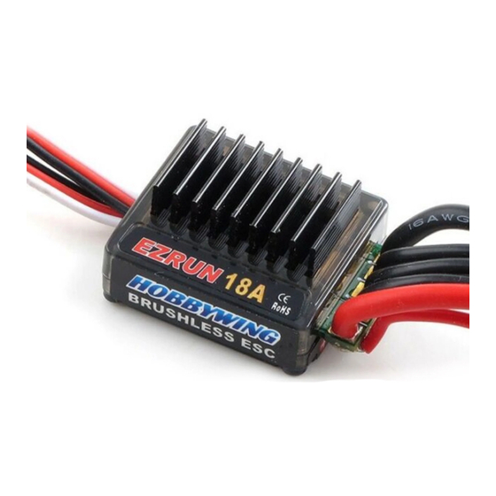
Programming and Calibration of EZRUN 18A ESCs
Having worked out that the occasional cutout of one of the thrusters in the
HobbyKing® ™ Brushless Car ESC 10A w/ Reverse ESCs overload protection rather than just an
inappropriately high battery protection voltage threshold, I replaced the electronic speed controllers with the
HobbyWing EZRUN 18A ESCs as used by the OpenROV project. Seeing as the original ROV design made
allowance for these this was an easy substitution. The big difference is in the programming and calibration
of these ESCs which don't conform to the typical calibration methods used and require a little more user
input.
This page describes the method for programming the HobbyWing EZRUN 18A ESCs, their settings, and the
subsequent calibration of the ESC using an Arduino. The Arduino was used to calibrate the ESCs to ensure
the control signals were compatible with the main ROV control sketches. Because of the need for user input
during the calibration sequence, the calibration process will not be able to be incorporated into the main ROV
control sketches as was originally intended in the development of the
Programming and calibration of the HobbyWing EZRUN 18A ESCs was carried out without the ESCs being
installed on the ROV electronics pod. Because the switch and "SET" button on the ESC are both accessible
when the ESC is installed calibration and programming can be done at any time.
Basic Specifications
Continuous Current:
Burst Current:
Resistance:
Suitable for Battery Cells:
BEC Output
There is a suggestion that 3 cell LiPo needs a cooling fan. This is not used in the OpenROV and hopefully
the thermal conductivity through the wall of the ROV electronics pod and the lower voltages associated with
the LiFePO
batteries will be enough to keep the temperatures within a tolerable level.
4
Programming the ESC
To program each HobbyWing EZRUN 18A ESC I hooked them up to a battery and Servo Tester as shown
below. The servo tester was set to the middle of its range to simulate a neutral throttle position. Initially the
ESC switch should be OFF.
18A
50A
0.01Ω
2S LiPo and 3S LiPo
6V/1A
Pool Test
was due to the
ROV control
system.
Advertisement
Table of Contents

Subscribe to Our Youtube Channel
Related Manuals for HobbyKing EZRUN 18A ESCs


Summary of Contents for HobbyKing EZRUN 18A ESCs
- Page 1 I replaced the electronic speed controllers with the HobbyWing EZRUN 18A ESCs as used by the OpenROV project. Seeing as the original ROV design made allowance for these this was an easy substitution. The big difference is in the programming and calibration of these ESCs which don't conform to the typical calibration methods used and require a little more user input.
- Page 2 A word of warning about the default settings on the HobbyWing EZRUN 18A ESCs: The default settings from the factory DO NOT match the default settings listed in the user manual. The most significant of these is the Low Voltage Cut-Off Threshold. Its default is “Non-Protected” which means the ESC will not protect your battery from low voltage.
- Page 3 Program Table Beep Codes ● ●● ●●● ●●●● ▬ ▬● ▬●● ▬●●● ▬●●●● ● = short ▬ = long ● Running Mode Forward with Brake Forward/Reverse Rock Crawler with Brake ●● Drag Brake Force 100% ●●● Low Voltage Cut-Off Threshold Non-Protected 2.6V/Cell 2.8V/Cell...
- Page 4 To access the programming mode turn off the ESC, then press and hold the SET key as you turn it on again. Keep holding the SET key as the ESC does a series of 13 short beeps while flashing the red LED, and then keep holding the SET key as the ESC signals which programmable item it is up to.
- Page 5 The connections to the Arduino are; the servo control wire of the ESC is connected to digital pin D3 (which is suitable for PWM) • the red LED connects to analogue pin A1 • the green LED connects to analogue pin A2 •...
- Page 6 The Arduino will allow this to sink into the ESC and signal completion of the process by flashing its own green LED. The ESC can be turned off and removed from the system. To do another ESC, connect another ESC as shown and hit the Arduino's reset button to begin the process again.
- Page 7 //minimum and maximum that the ESC will recognise. // 600 and 2250 work. throttle = 0; //Set the throttle to minimum ESC.write(throttle); //Set the ESC signal to minimum ie 100% reverse. //At this point the ESC's power should be connected. lcd.clear(); //make sure screen is clear again. lcd.setCursor(0,0); //Move cursor to top left corner lcd.print("Connect Battery"); lcd.setCursor(0,1); lcd.print("Hold SET 2 sec"); delay(10000); //Allow the user time to connect the battery to //the ESC and hold the SET button. The button MUST be released //before the ESC's red light stops flashing otherwise the ESC //will enter programming mode. lcd.clear(); //make sure screen is clear again. lcd.setCursor(0,0); //Move cursor to top left corner lcd.print("Moving 2 Neutral"); redBlink(); //Jump to the Blinking red LED subroutine throttle = 90; //Set the throttle to 90 degrees (neutral) ESC.write(throttle); //Set the ESC signal to the neutral position. lcd.clear(); //make sure screen is clear again. lcd.setCursor(0,0); //Move cursor to top left corner lcd.print("Press SET Button"); delay(10000); // allow a 10 second delay for the ESC to signal //that it is done. lcd.clear(); //make sure screen is clear again. lcd.setCursor(0,0); //Move cursor to top left corner lcd.print("Moving 2 Max"); redBlink(); //Jump to the Blinking red LED subroutine throttle = 180; //Set throttle to the maximum forward position. ESC.write(throttle); lcd.clear(); //make sure screen is clear again. lcd.setCursor(0,0); //Move cursor to top left corner lcd.print("Press SET Button"); delay(10000); // allow a 10 second delay for the ESC to signal //that it is done. lcd.clear(); //make sure screen is clear again.
- Page 8 //Blink the green LED to signal end of process digitalWrite(grnLEDpin, HIGH); delay(1000); digitalWrite(grnLEDpin, LOW); delay(1000); void redBlink() //Blink the redLED to signal the user to press the "Set" button for(int i = 1; i < 6; i++) //do the sequence for 10 seconds. { digitalWrite(redLEDpin, HIGH); delay(1000); digitalWrite(redLEDpin, LOW); delay(1000); } I trust this helps make things a bit easier for you as you set up a Hobbywing EZRUN 18A ESC for use in whatever project you are applying them. Hamish Trolove www.techmonkeybusiness.com...
Need help?
Do you have a question about the EZRUN 18A ESCs and is the answer not in the manual?
Questions and answers