Advertisement
Quick Links
Advertisement

Related Manuals for GROUNDTECH DISCOVERY Series

Summary of Contents for GROUNDTECH DISCOVERY Series
- Page 1 DISCOVERY SERIES USER MANUAL...
- Page 2 Reproduction, distribution and copying of this user guide un- authorized by the Groundtech Detectors is strictly prohibited. General Information GROUNDTECH products should be used with caution as one do with electronic devices. Search coils and main unit should be used with caution; they should be protected against impacts and hard objects and refrained from applying excessive force.
-
Page 3: Initial Setup Screen
Repair Any repairs resulting from technical malfunctions for a period of two (2) years from the date you purchased the product are free. Contact your dealer for product service or inquiries. The unit is inspected by a qualified technician and repaired if nec- essary. - Page 4 1. Language: Select the display language that you want to use your device in. 2. Region: Select the region that you use your device in. This selection will enable you to get the hour, date and location information of your area. 3.
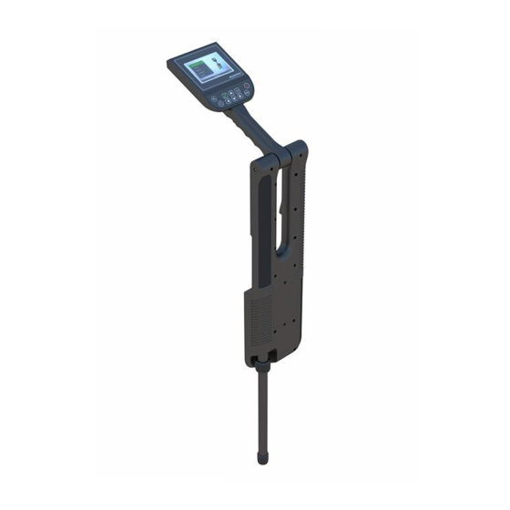
- Page 5 BUTTONS and SETTINGS Buttons on the device; Zoom Buttons: Zoom in and out of the 3D graphic and select the type of ground. OK Button: Allows you to select a menu. Navigation Buttons: Allows you to ride in the menu. Back Button: Allows you to go back to the previous screen.
- Page 6 Charge Headphone On the right side of your device is the headphone jack and on the left is the charging jack. Only charge your device with the included charging adapter. The battery charging lamp on the main body will flash red while your device is charging. If your battery is fully charged, it will turn to stationary red light.
-
Page 7: General Settings
GENERAL SETTINGS The general settings section of your device; Activation: To activate the external mobile applications of your device, read the square code on the screen or enter the numbers on the screen. The numbers on this screen are also the identification number of the product. | 6 |... - Page 8 Region Settings: In this menu, you can change the device display language, the unit of measurement you use, and the time zone. Appearance: You can change the device menu theme and the background color of the 3D graph review screen. Sound: You can adjust the volume of the device and turn on/off the vibration function.
- Page 9 SEARCH MODES - 3D GROUND SCAN 3D Ground scanning allows you to create 3D graphs based on whether you scan a specific area. There are two options in the ground scanning function: Automatic and Manual. You do not need to press any button in automatic scanning for each num- ber of signal pulses entered, and you need to press the start button for each signal in manual scanning.
- Page 10 PRE-SCAN SETTINGS IN AUTO & MANUAL SCAN When you select Automatic ground Scan, you will be directed to the settings you need to make before the search. Measurement Type: You must choose the number of steps or meters. In the step option, you have to enter step numbers in step and line options.
- Page 11 Line Step Line: You must enter the row size of the search area in meters or steps according to the unit you have selected in the "Meas- urement type" section. Depending on the number of signal pulses you have entered, you should go to the next scan row when the signal pulses are over.
- Page 12 0.8 – 4 seconds Step Duration: If you want the device to wait between each signal pulse, you can select not less than 0.8 seconds. When you increase the time, the waiting time will increase. This fea- ture is activated in the automatic search option. Left Right Starting Point: You can adjust your scanning starting point by...
- Page 13 AUTO & MANUAL 3D SCAN Depending on the settings you made before the search, the 3D Ground scan will begin. During scanning, you will see colors such as green, red, yellow, and blue, depending on the meas- urements you have taken. All metallic objects and objects with high magnetic effect are mostly red, some are orange, Underground cavities, filled soils, cavities are blue, you can see the soil as green without any changes and anomalies.
- Page 14 When the number of signal steps and lines entered is com- plete, the device will automatically exit the search function and direct you to the 3D Viewer function for a detailed analysis of the received data. If you want to end the search before the number of signal steps entered and the line row is completed, you must press the Back button on the device.
- Page 15 screen. If you select No, you can continue your search from where you left off. To obtain regular and accurate data, you must complete the number of signal steps and the number of lines entered. 3D MONITOR AND GRAPHICAL ANALYSIS Your device will direct you to this screen after scanning so you can examine the graphics you have obtained with 3-Dimen- sional Ground Scanning in detail.
- Page 16 Start: Allows to go back to the main screen from 3D Viewer function. This view allows you to analyze the data in more de- tailed lines. There are 4 different graph analysis features on the 3D Viewer function. 3D Rotation: You can use the direction but- tons on the device to ro- tate your graph left-...
- Page 17 Scanning Details: You can see numerical val- ues of your data and get information about depth by choosing type of soil. You can go around the graph with direction buttons and examine the point details. Depth Information: You can find out the general depth information of the measurement and see the start and end...
- Page 18 DETECTION & METAL-MINERAL DIFFERENTIATION Metal Mineral • Metallic objects have a distinct shape, while minerals usually have a messy and scattered appearance. • Metallic objects have red color, mineral substances are usually yellow and orange. • The most important property of metallic objects that dis- tinguishes them from minerals is that there is a signifi- cant numerical difference between them and soil in the collected data.
- Page 19 1- Soil Type 2- Ground Balance Value 3- Signal Value 4- Signal Depth There must be an in- crease of at least 15 units between the soil, which is shown with green on the graph, and metallic objects which are shown with red. For ex- ample, if the level of soil is 150, there should be a numerical value of at least 165-170 in order to be a metallic object pre- sent.
- Page 20 CAVITY DETECTION Tunnel Grave Artificially created underground cavities such as tunnels, chambers, tombs are seen as blue color in the graphic. In the event of any dents or soil filled in the underground, the data will be light blue, turquoise or light green. What you are searching for must have a distinctive shape and form, for example if you are searching for a structure that re- sembles a tomb, the blue area on the graph should be rectan-...
- Page 21 If there is a difference of a few units, this data indicates ground caused by rocks or superficial soil variations. When you go around the graph with direction buttons, you can see the soil balance value and numerical value of the selected point on the top bar.
- Page 22 For example, if the area you are working on is completely rocky, choose “concrete”, If it is stony, choose “stony”, If it is non-mineral; field-like, choose “light mineral”, If it has high mineral concentrations, choose “high mineral”. If you have no information or estimations about the type of soil, you can make several calculations in different options and compare them or choose “Overall”...
- Page 23 LIVE SCANNING Live scanning means search modes with 3 different search op- tions that allow you to make fast, 2-dimensional point detec- tions. Live scan: You can see objects with magnetic effect, metallic objects, grounds and structures buried underground faster. On live scanning screen, you can see all metallic objects and most of the objects that have magnetic effect with red, and some objects that have magnetic effect with orange, Tunnels, filled dirt and cav-...
- Page 24 screening option. In Dynamic Graph option, your device auto- matically detects the level of soil on your first scan and calcu- lates your scanning according to this level. If you press the OK button on your device during scanning, the device will in- stantly update the soil level and you can carry on scanning with this new level of soil.
- Page 25 with your bare hands during the scanning. This may cause se- rious injuries. CALIBRATION Wet soil can cause mistaking in your operations resistivity scanning. In order to minimize the rate of mistaking, you must perform soil calibration. For calibration settings, arrange the probes 1-2 meters apart and place 2 conducting probes on the ground.
- Page 26 Select the calibration option in the resistivity scan menu. Se- lect the line on which you have attached the probes and select Calibration. The calibration should now be completed. The data will be fixed as soil level. In automatic search or manual search modes, you can scan with the obtained calibration value.
- Page 27 4 conductive probes which come with your device to the ground, forming a square. Arrange the distance between two probes according to the depth you want to scan. Attach 4 conductive wires which come with your device to the output sockets of your device and the other ends to the conducting probes.
-
Page 28: Manual Mode
the device. You can switch to wire cage view with the Start BUTTON in the front part of the device. The colors on the graph correspond to; Green: Soil Blue: Ground Light blue: Water Yellow: Mineral Red: Metal. Also, the data on the right show the results per- ceived on the lines after scanning. - Page 29 and the other ends to the conductive probes. For example, connect to output sockets 1 and 2 with line A. Select Manual Mode from the device menu. Select the line where Conductive Probes are installed. The scan will begin. Af- ter the scan, you will see the measurement result graphically and numerically on the device screen.
-
Page 30: Frequently Asked Questions
3D Ground scan recorded files are sorted in order of record- ing. You can scroll through the recorded files with Up-Down arrow buttons. On the right, you can see a preview of your scan when switching between saved files. Press the OK button on the device to open the saved scan file. To delete your saved files, you can delete them using the De- lete option from the menu on the right. - Page 31 use this product with a device capable of running the Android operating system. Is it necessary to have an Internet or GPS connection while using this device? There is no requirement to use an Internet connection for the performance of the scanning procedures. GPS connection is required for the local time and location information of the area where you are in.
- Page 32 USB 2.0 connector or higher level of Bluetooth, 1 GHz Proces- sor, 1 GB RAM (Memory), 250 MB Free storage on hard disk, DirectX9 graphic card. For Android devices, 5.0 and higher operating system and min- imum 1 GB ram of memory. Is the device water-resistant? No.
- Page 33 international service points of the manufacturer/distributor thereof for repairs and maintenance. The accessories supplied with the device are broken/lost, are they under warranty? All the accessories supplied with the device are not under war- ranty. The main unit of the device is under international war- ranty of 2 years.
- Page 34 under the ground for an extended period of time (metals such as iron and steel) could easily be detected. You may find in- gots, coins or other treasuries if they have been buried under the ground for an extended period of time and they are within a metal with magnetic field.
- Page 35 reservoir or an underground water flow may be seen in the graphics as a space. Is it possible to make a search in any direction when scan- ning? You need to make your scanning always in the north-south di- rection. Otherwise, the data you obtain may be wrong. When I scan the same area in different times, I obtain differ- ent results and different graphics, what is the reason of this? The magnetic measurement method, the magnetic sensitivity...
- Page 36 What should the maximum distance between the device and the ground be when scanning? The distance between the ground and the sensor should be up to 15 cm and remain unchanged when scanning. How fast can I scan with the device? You should scan in a normal walking speed.
- Page 37 www.groundtech.com.tr...
Need help?
Do you have a question about the DISCOVERY Series and is the answer not in the manual?
Questions and answers