Table of Contents
Advertisement
Quick Links
Advertisement
Table of Contents

Related Manuals for ParTech TurbiTechw2 LR

Summary of Contents for ParTech TurbiTechw2 LR
- Page 1 INSTRUCTION MANUAL TurbiTechw² LR Sensors...
- Page 2 ** This page is intentionally left blank **...
-
Page 3: Table Of Contents
TurbiTechw² LR Instruction Manual Table of Contents 1 Foreword................................ 6 2 Introduction..............................7 2.1 Manual Conventions..........................7 2.2 WaterWatch² Trademark........................7 2.3 Scope of Manual............................ 7 2.4 External Sensors........................... 7 3 Safety Precautions............................8 3.1 General..............................8 3.2 Electrical installation..........................8 3.3 Operating............................... - Page 4 TurbiTechw² LR Instruction Manual 7.4.3 S:0x Remove..........................17 7.4.4 S:0x Modbus Address........................17 7.4.5 S:0x Clean Config........................17 8 Measurement Configuration......................... 19 8.1 Measurement Config..........................19 8.1.1 Measurement Status........................19 8.1.2 Add Measurement........................19 8.2 M:0x – Measurement Channel......................20 8.2.1 M:0x Info............................
- Page 5 TurbiTechw² LR Instruction Manual 15 Technical Specification..........................32 15.1 Physical............................. 32 15.2 Electrical............................32 15.3 Measurement............................. 32 225769IM - Issue - 05 Issue Date 30/04/2019 Page 5 of 34...
-
Page 6: Foreword
Waterwatch² range. The sensors are designed for use with the 7300w² Monitor. The term TurbiTech is used for any Partech self-cleaning, Suspended Solids or Turbidity Sensor. The TurbiTechw² LR Sensor has been specifically designed to monitor final treated, potable and filter water. -
Page 7: Introduction
Training in the use of the 7300w² Monitor and sensors can be provided, please contact Partech for further information. Icons have been used throughout this manual to draw your attention to precautions and useful notes. -
Page 8: Safety Precautions
Maintenance instructions for the TurbiTechw² sensor should be carried out as specified in this instruction manual. Failure to carry out regular maintenance could invalidate the Warranty. Services and repairs must be carried out by a Partech engineer. Partech can provide a service contract for your system. Please ask for details. -
Page 9: End Of Life Disposal
Any calibration solutions should be disposed of as described in the Manufacture Safety Data Sheet accompanied with the calibration solution. Partech can provide recycling and disposal of your old Partech equipment, and may also provide the same service for other manufactures equipment when replaced with Partech equipment. -
Page 10: The Sensor And Installation
Whilst every attempt has been made to ensure that these instructions are correct, common sense and good engineering practice should always be used, as every installation can present a new set of challenges and difficulties. If you are in any doubt please contact Partech or your local distributor for further information. TurbiTechw² LR Sensor All the TurbiTechw²... -
Page 11: Mechanical Installation
Regulations governing the use of equipment in contact with potable water exist and these need to be understood by the user of this product. It is Partech's belief that the low surface area in contact with the potable water and the normal installation practise of feeding the sample stream to waste mean that this product is suitable for use in potable water treatment processing. -
Page 12: Transmitter Module
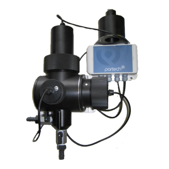
TurbiTechw² LR Instruction Manual 5.2.1 Transmitter Module The transmit module, positioned to the right of the flow cell, contains the solid-state emitter and the light intensity control components. The light intensity is controlled automatically preventing signal degradation with time. The light beam passes through the sample water. Light is scattered and focused onto the target area. -
Page 13: Sample Pressure
A De-Bubbler is available, but will generally not improve situations where micro-bubbles are problematic. For evening out erratic flow, including occasional air intrusions, the De-Bubbler is an ideal solution. Please talk to Partech about options for mitigating sample conditioning issues. -
Page 14: Electrical Installation
When routing the sensor cables, please ensure the cable is separated from any mains cables. Although the Partech w² sensors have a high resistance to interference, separation of mains and data cables is good practice and should always be followed where practical. -
Page 15: Extending Sensor Cables
Sensors are usually supplied with 10M cables (longer cables can be provided if requested). These cables can be extended to a maximum length of 100M. To ensure optimum performance, only use Partech ModTechw² cable for extensions. Partech can supply junction boxes to allow for cable extensions. These should be used on all installations where the cable length from the sensor to the monitor exceeds 20M (Partech Junction boxes include on-board filtering for long cable lengths). -
Page 16: Sensor Configuration
TurbiTechw² LR Instruction Manual Sensor Configuration M:01 0.14 Before attempting to configure the sensor, please read the user manual that came with your monitor. The monitor manual will introduce you to the basic set-up of the monitor, and will familiarise you with the monitor menu structure and buttons. -
Page 17: S:0X Turbitechw² Lr (0-30)
S:01 Clean Config 7.4.2 S:0x Info This function provides a range of diagnostic information that may be requested by Partech for fault finding 7.4.3 S:0x Remove This allows the sensor to be removed for re-configuration of the monitor or if a sensor has been added on error. - Page 18 TurbiTechw² LR Instruction Manual S:0x Clean Service This allows the user to reset the clean counter when a service is carried out. S:0x Clean Info This option reports the number of cleans carried out by the sensor since the last reset, the time of the next clean and estimated service life Page 18 of 34 225769IM - Issue - 05 Issue Date 30/04/2019...
-
Page 19: Measurement Configuration
TurbiTechw² LR Instruction Manual 8 Measurement Configuration The monitor leaves the factory without any measurements configured. Measurements can only be added after installing the relevant sensor(s). Once the sensor(s) have been registered with the monitor and installed, the measurements will now be available. -
Page 20: M:0X - Measurement Channel
TurbiTechw² LR Instruction Manual M:0x – Measurement Channel MEASUREMENT CONFIG Selecting a measurement channel will reveal a new sub-menu associated Measurement Status Add Measurement with that measurement. In MEASUREMENT CONFIG press M:01 Turbidity (S:01) highlight the required measurement and press The sub-menu is as follows: 8.2.1 M:0x Info... -
Page 21: Calibration
The most accurate method of calibration is using a primary standard, i.e. formazine solution. This procedure has associated health risks, therefore Partech supply a dry secondary standard with each flowcell. These standards have been given a calibrated value that is equivalent to formazine in NTU. Under normal circumstances and the correct storage these standards will last the life time of the instrument. -
Page 22: Calibration Zero
TurbiTechw² LR Instruction Manual Protective gloves. • Cleaning Materials • Prior to taking any measurements, thoroughly wash any containers used. Calibration Zero To calibrate the sensor, switch off the inlet hose and remove the cleaning module. The cleaning module is located in the top of the measuring cell and locates with a screwed collar. A location peg makes sure the module is correctly aligned during replacement. -
Page 23: Calibration Span
TurbiTechw² LR Instruction Manual 9.4 Calibration Span To calibrate the sensor span, switch off the inlet hose and remove the cleaning module. The cleaning module is located in the top of the measuring cell and locates with a screwed collar. A location peg makes sure the module is correctly aligned during replacement. -
Page 24: Take Sample
TurbiTechw² LR Instruction Manual 9.5.1 Take Sample The TurbiTechw² sensor should filled with an instance of the desired sample representative of the normal operating conditions expected from the sample point. The cleaning motor must be present to exclude light. Allow the reading to stabilise before entering the Take Sample’ routine. Care is needed to ensure that air bubbles are not causing a calibration error. -
Page 25: Sample Result
TurbiTechw² LR Instruction Manual 9.5.2 Sample Result Once the sample result has been established via the ‘Take Sample’ routine above, the result can be entered into the sensor in the following way: MEASUREMENT CONFIG Press to show the “MAIN MENU”. Measurement Status Select “MEASUREMENT CONFIG”... -
Page 26: Maintenance
In certain circumstances it may be required to replace both modules as a transmit/receive pair as supplied by Partech. However a preferable route would be to return the complete flow cell to Partech for servicing. -
Page 27: Spares
TurbiTechw² LR Instruction Manual 11 Spares 11.1.1 Service Parts 201010..........WaterWatch2310/WaterWatch2970/ColTechw² LR/ColTechw² - Replacement Cleaner Arms/Wiper Blades (pack of 3) When ordering seal packs, always provide the model number and serial number of the sensor to ensure the correct seal pack is supplied. 225769IM - Issue - 05 Issue Date 30/04/2019 Page 27 of 34... -
Page 28: Sensor Faults
Suspended Solids/Turbidity present in the sample against the specified range of the sensor. It is possible that the nature of the application has changed. If the problem persists please contact Partech or your local representative for further guidance. 12.2.2 Over range/Under range This indicates that the sensor is receiving a valid measured value that is outside the limits of the measurement configuration. -
Page 29: General Application Notes
TurbiTechw² LR Instruction Manual 13 General Application Notes 13.1 Preparation of Formazin Turbidity Standard Preparation of Formazin Turbidity Standard for Calibration. 13.1.1 Health & Safety Precautions The chemicals used when following this procedure are harmful, therefore the correct safety precautions must be carried out. During handling, avoid inhalation and contact with the eyes or skin. Wash hands thoroughly after use. - Page 30 TurbiTechw² LR Instruction Manual Solutions made by diluting the 4000 FTU standard should also be stored in suitably labelled amber glass bottles and kept in a cool dark place. Solutions above 400 FTU have a shelf life of one month after which they should be discarded.
-
Page 31: Technical Support
Digital photos can also be useful to determine correct installation and suitability to the application. • 14.1 Returning Equipment for Repair If equipment needs to be returned to Partech for repair or service the following address should be used: SERVICE DEPARTMENT PARTECH INSTRUMENTS... - Page 32 High Range........0 – 50 to 0 – 500 FTU It has been assumed that 1 NTU = 1 FTU for the purpose of this statement, please refer to Partech for further details Accuracy.........Better than ±2% FSD on real sample Resolution........±1% FSD or better (0.1 FTU for low range version) Repeatability........Better than ±1% FSD on real sample...
- Page 33 TurbiTechw² LR Instruction Manual 225769IM - Issue - 05 Issue Date 30/04/2019 Page 33 of 34...
- Page 34 Partech Instruments Rockhill Business Park, Higher Bugle, St Austell,Cornwall, PL26 8RA,UK Tel: +44(0)1726 879800 Email: info@partech.co.uk Web: www.partech.co.uk...
Need help?
Do you have a question about the TurbiTechw2 LR and is the answer not in the manual?
Questions and answers