
Subscribe to Our Youtube Channel
Related Manuals for monolith HTP-1


Summary of Contents for monolith HTP-1
- Page 1 HTP-1 16 Channel H ome Theater Processor User Manual P/N 37887 Updated October 14, 2020 © 2019, 2020 Monoprice Inc. All rights reserved.
- Page 2 HTP-1 Installation and User Guide Release 1.8.1 (This page left blank) HTP-1 User Manual Page 2 V1.8.1...
-
Page 3: Table Of Contents
HTP-1 Installation and User Guide Release 1.8.1 Table of Contents Table of Contents Safety Warnings and Guidelines Licenses Introduction Customer Service Package Contents Requirements Product Overview Front Panel Rear Panel Front Panel LCD Display Remote Control Web GUI Home Page... - Page 4 HTP-1 Installation and User Guide Release 1.8.1 Multiple Subwoofers and Dirac Live Bass Control™ Mapping Channels to Speakers Speaker Setup Setting Speaker Size Enabling Speakers Dolby® Enabled Speakers Example Speaker Setups Back Panel Mapping Display Example 7.1.4h Speaker Configuration (Upper Level On the Wall) Example 7.2.6 Speaker Configuration (Upper Level On the Ceiling)
- Page 5 Sound Enhancement Page Using Surround Modes Wide Synth Bass Enhancement (AKA Bass Reinforcement) Audio Features Night Mode Dialog Enhancement Loudness For Highest Quality Audio Connectivity Setting up ARC/eARC and CEC Connecting HTP-1 to TV for ARC/eARC HTP-1 User Manual Page 5 V1.8.1...
- Page 6 HTP-1 Installation and User Guide Release 1.8.1 CEC Settings CEC Control Options Alternate TV Input TV Audio Priority System Audio Using Wi-Fi Choosing DHCP or Static IP Address Assignment Bluetooth System Page Support Features Video Features UHD Support EDID Management...
- Page 7 HTP-1 Installation and User Guide Release 1.8.1 RF Exposure Statement for FCC Notice for Industry Canada Special Thanks Revision History Important Information HTP-1 User Manual Page 7 V1.8.1...
-
Page 8: Safety Warnings And Guidelines
HTP-1 Installation and User Guide Release 1.8.1 Safety Warnings and Guidelines Please read this entire manual before using this device, paying extra attention to these safety warnings and guidelines. Please keep this manual in a safe place for future reference. -
Page 9: Licenses
Please check for updates on the i nfo p age of the HTP-1 web interface. Do also read the release notes found on the i nfo p age. The release note gives the latest information about what has changed in the software. -
Page 10: Package Contents
1x AC Power Cord Requirements ● The HTP-1 must be connected to an existing Ethernet wired or wireless network for initial configuration. Computers or mobile devices connected to the network can be used to control and configure the HTP-1. The HTP-1 can be operated with no network connection if no more configuration is required. -
Page 11: Product Overview
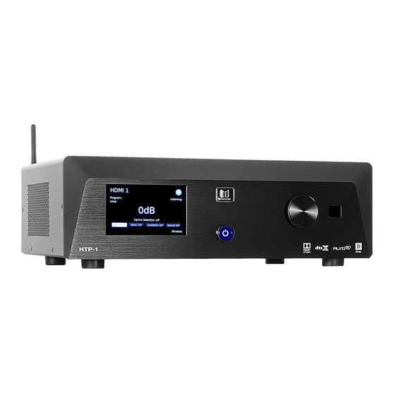
HTP-1 Installation and User Guide Release 1.8.1 Product Overview Front Panel 1. LCD Display: T his 5" t ouchscreen displays the volume level, selected input, upmix selection, [ s1] and various other system statuses. See the F ront Panel LCD Display section below for details. -
Page 12: Rear Panel
The main signal is mixed down to a stereo signal. 6. TRIGGER INPUT: A 3.5mm trigger input turns the HTP-1 on when a 12V signal is applied. The HTP-1 will go into standby mode when the trigger signal is removed. Note that the M aster Power Switch... - Page 13 To assure a completely clean reboot, allow the HTP-1 to be powered down for 15 seconds before powering on again via the master power switch.
-
Page 14: Front Panel Lcd Display
7. Wi-Fi Setup: Touch the g ear icon to display the W i-Fi® Setup screen. See the W I-FI SETUP section for details. If the icon is yellow, a software update is available for the HTP-1. HTP-1 User Manual Page 14 V1.8.1... - Page 15 U sing Surround Modes s ection for details. 9. Wireless: If the HTP-1 is connected to a wireless connection, the I P Address will be displayed in the lower right corner. The sample screenshot above shows 1 69.254.8.119 for the wireless IP address.
-
Page 16: Remote Control
HTP-1 Installation and User Guide Release 1.8.1 5. HDMI+: Press the H DMI+ button to Remote Control cycle forward through the eight HDMI® inputs as well as the TV input. When using this button the GUI will display the HDMI input that will be selected after a short timeout period expires (about 3 seconds). - Page 17 HTP-1 Installation and User Guide Release 1.8.1 17. DIALOG: Press the + button to increase described in more detail under “ A udio the D IALOG volume level or press the - Features ” . 13. BT PAIR: Press the B T PAIR button to button to decrease the ...
-
Page 18: Web Gui Home Page
HTP-1 Installation and User Guide Release 1.8.1 Web GUI Home Page 1. Active Input: The current A ctive Input is displayed in the upper left corner. The sample screenshot above shows M agnavox as the A ctive I nput . The specific text used for each input is configured on the ... - Page 19 HTP-1 Installation and User Guide Release 1.8.1 7. Modes: Click the buttons to toggle the state of the N IGHT , D IRAC , L OUDNESS , and D IALOG special listening modes. 8. Setup: C lick the g ear icon to display the S ystem Configuration screen with the S PEAKERS , CALIBRATION...
-
Page 20: Basic Setup
1. Prepare a location for the HTP-1. Ensure that it is not in an enclosed cabinet, that it has at least 3" of space around and above the unit, and that it is in a well-ventilated area to ensure sufficient cooling airflow. - Page 21 Master Power Switch on the rear panel. Note that the HTP-1 has a slow boot/eco mode and a fast boot mode. By default, the unit is configured for slow boot, which takes about a minute. The slow boot mode uses a lower power standby mode (below 500mW).
-
Page 22: Initial Wifi Setup
Initial WiFi Setup The HTP-1 serves a web page via its Ethernet connection and this is used for all setup. You must connect to a network. If you wish to use a WiFi connection exclusively, begin by booting up the HTP-1 with a wired connection. -
Page 23: Interface Description
HTP-1 Installation and User Guide Release 1.8.1 Interface Description If you followed the Basic Connections instructions above you should be ready to use some of the more C lick the g ear icon in the upper right corner of the W eb GUI Home Page to advanced features. -
Page 24: Speaker Configurations
Dirac filter. The message near the top of the page also indicates which bass manager is running. Options are the Dirac bass manager or the HTP-1 bass manager. The Dirac bass manager can chosen when a Dirac calibration is constructed. - Page 25 HTP-1 Installation and User Guide Release 1.8.1 HTP-1 User Manual Page 25 V1.8.1...
-
Page 26: Speaker Location Diagrams
Dolby Atmos™ favors top speakers on the ceiling. DTS-X™ and Auro3D™ favor height speakers on the wall. As the following section on mapping channels to speakers points out, the HTP-1 uses standard compliant mapping techniques to support any of these speaker locations. - Page 27 HTP-1 Installation and User Guide Release 1.8.1 DTS Azimuth DTS Elevation DTS Nominal Speaker Range Range (Azimuth, Speaker Position Notation (degrees) (degrees) Elevation) Comment Center (0,0) Left -30 to -45 (-30,0) Right 30 to 45 (30,0) Left Surround -100 to -120 (-110,0) DTS 5.1 layout...
-
Page 28: 5.1 Vs 7.1 Surround Speakers
HTP-1 Installation and User Guide Release 1.8.1 5.1 vs 7.1 Surround Speakers The surround speakers are illustrated at 90 degrees in the diagram above. The positioning of this speaker pair is not completely agreed between the three codecs. 90 degrees is recommended by Dolby and DTS for a 7.1 system. DTS refers to these as the “side surrounds”... -
Page 29: Valid Speaker Configurations
Release 1.8.1 Valid Speaker Configurations The HTP-1 can support up to 16 output channels. There can be up to 9 main level channels, 6 upper/height channels, and up to 5 subwoofers. These can be allocated in various ways. Some of the more complex ways are discussed in the following sections. - Page 30 Dolby content is typically authored with the upper level speakers in the ceiling. DTS® and Auro-3D® content is typically authored with the speakers High on the walls. The HTP-1 remaps the source material to match the user-defined speaker configuration. The following table explains the Upper level speaker...
-
Page 31: Multiple Subwoofers And Dirac Live Bass Control
Multiple Subwoofers and Dirac Live Bass Control™ The HTP-1 can support up to 5 subwoofers. More than one subwoofer can minimize dead spots in the low frequency material. The trim (gain) and delay can be independently adjusted for each subwoofer. -
Page 32: Speaker Setup
HTP-1 Installation and User Guide Release 1.8.1 2) A 5.1 DTS stream is usually authored with the surround speakers at 110 degrees from the listening position (see the S peaker Location Diagrams on previous page). A 7.1 speaker setup places surrounds (sides) at 90 degrees and rear speakers at 135 degrees. -
Page 33: Setting Speaker Size
HTP-1 Installation and User Guide Release 1.8.1 The speaker configuration is set by clicking on the toggle switches in the left-most column. Blue indicates that the speaker is enabled. When you have enabled a speaker, or set of speakers, they will appear in the illustration on the right hand side of the pane, which will help you place the speakers in the correct position in the room. -
Page 34: Enabling Speakers
Choosing a cutoff that is clearly in the linear region of the speaker ensures that the crossover operates as designed and is not affected by the natural filtering of the speaker. The HTP-1 uses a fourth-order Linkwitz-Riley crossover. -
Page 35: Dolby® Enabled Speakers
The “5.1.2” Atmos configuration uses the top-middle pair. DTS-X streams are likely authored using four high speakers. The HTP-1 “remaps” any source arrangement to match the speaker setup you choose using algorithms provided by the decoder. This is why you should describe/configure your speaker setup as accurately as possible, though few people will be able to tell the difference if a pair of speakers labeled “top front”... -
Page 36: Example Speaker Setups
The back panel of the unit is shown below along with a diagram of the XLR connectors on the back of the HTP-1. The diagram will be used in the following sections to show you how to connect an amplifier to the unit for various speaker configurations. -
Page 37: Back Panel Mapping Display
HTP-1 Installation and User Guide Release 1.8.1 Back Panel Mapping Display The assignment of output channels is always available at a page that is linked from the bottom of the speaker configuration page. This assignment can vary with the choice of speakers. Note that this picture shows the speaker mapping, and not their activity. -
Page 38: Example 7.1.4H Speaker Configuration (Upper Level On The Wall)
HTP-1 Installation and User Guide Release 1.8.1 Example 7.1.4h Speaker Configuration (Upper Level On the Wall) This speaker configuration uses 7 surround sound speakers, 1 subwoofer and 4 height speakers. The height speakers are mounted high on the walls, in the corners of the listening area. -
Page 39: Example 7.2.6 Speaker Configuration (Upper Level On The Ceiling)
HTP-1 Installation and User Guide Release 1.8.1 Example 7.2.6 Speaker Configuration (Upper Level On the Ceiling) This speaker configuration uses 7 surround sound speakers, 2 subwoofers and 6 height speakers. The height speakers are mounted in the ceiling. HTP-1 User Manual Page 39 V1.8.1... -
Page 40: Example 9.3.4 Speaker Configuration (Upper Level On The Ceiling)
HTP-1 Installation and User Guide Release 1.8.1 Example 9.3.4 Speaker Configuration (Upper Level On the Ceiling) This speaker configuration uses 9 surround sound speakers, 3 subwoofers and 4 height speakers. The upper front speakers are mounted in the ceiling. The upper rear speakers are Dolby Enabled. -
Page 41: Example 9.1.6 Speaker Configuration (Upper Level On The Ceiling)
HTP-1 Installation and User Guide Release 1.8.1 Example 9.1.6 Speaker Configuration (Upper Level On the Ceiling) This speaker configuration uses 9 surround sound speakers, 1 subwoofer and 6 height speakers. The height speakers are mounted high on the walls, in the corners of the listening area. -
Page 42: Configure The Bass Manager
HTP-1 includes a bass manager typical of surround sound processors. It requires the user to describe the low frequency capabilities of each speaker. If you don’t have specifications for your speakers, a basic Dirac Live®... - Page 43 HTP-1 Installation and User Guide Release 1.8.1 HTP-1 User Manual Page 43 V1.8.1...
- Page 44 HTP-1 bass manager. When the Dirac Live Bass Control filter is activated, the regular HTP-1 bass manager is disabled. This is indicated near the top of the speaker configuration page and on the Dirac button. Dirac Bass Control engaged:...
-
Page 45: Calibration
HTP-1 Installation and User Guide Release 1.8.1 Calibration Calibration is a critical part of good sound. The HTP-1 collects calibration items on the calibration page. The calibration page contains a lot of information. This section describes each item to help you understand. -
Page 46: Volume Range And Maximum Output Voltage
A M aximum Output Level (formerly amplifier sensitivity) control is provided on the C ALIBRATION page so that the output voltage of the HTP-1 can be matched to the input sensitivity of your amplifier. The input sensitivity of an amplifier is defined as the voltage at which the amplifier is driven to clipping. -
Page 47: Recommendations On Setting The Maximum Output Level
If the input sensitivity of your amplifier is unknown, begin by setting maximum output level of the HTP-1 to 1 volt. Set the max listening volume to zero. Run the volume up and see if it gets as loud as you want it to be. If you think it should be louder, increase the maximum output level. -
Page 48: Dirac Calibration
The HTP-1 system makes it easy to do a Dirac® calibration, and you should do such a calibration. Setting up your speakers correctly is a key part of getting the best sound out of your system. Dirac also offers a more sophisticated bass management system referred to as Dirac Live Bass Control. -
Page 49: Calibration Steps
Dirac usage. 4) Open DiracLive and connect to the Monolith HTP-1. The displayed name is set on the S YSTEM tab of the S ystem Configuration screen. The Dirac Live tool uses common networking protocols to find the HTP-1. - Page 50 HTP-1 Installation and User Guide Release 1.8.1 7) Set the volumes for calibration. The volume control on the left side of the Dirac screen exactly matches that used by the remote control. You can adjust it with the remote control. The Dirac program sets the volume initially to -30dB.
- Page 51 HTP-1 Installation and User Guide Release 1.8.1 9) Proceed to the m easure s creen and hear the sweeps. When a measurement is successfully completed you’ll see the frequency response displayed. While it’s OK to try things out with one sweep, a good calibration uses more measurements.
- Page 52 HTP-1 Installation and User Guide Release 1.8.1 Here is an example showing the spread: 12) The “groups” at the right allow you to easily see one set of speakers. The illustration above shows the “spread” between various measurements. The dip at the crossover shows that more work is required to tune the crossover and the target curve.
- Page 53 Dirac Live tool, then close it again. 17) Click the g ear icon on the W eb GUI Home Page , then click the C ALIBRATION tab. The HTP-1 in the sample screen below is set up for a 5.1 configuration and a 5.1 calibration is chosen. If a calibration is for less speakers than the current configuration, the uncalibrated channels will then be passed without any filtering.
-
Page 54: Dirac Bypass
Critically, the detailed room correction filter is applied. If a Dirac Live Bass Control filter is selected, the buttons in the GUI will show “Dirac On BC” and the HTP-1 bass manager is disabled so that Dirac can handle the bass management. -
Page 55: Dirac Off
Release 1.8.1 Dirac Off Dirac delay and trim values are ignored. User trims are used. The HTP-1 bass manager is engaged. The signal is presented without modification. The GUI says "Dirac Off". This three step cycle is known as the “Dirac bypass loop”. As the result of a Dirac calibration can have large negative trim values, the system may be much louder with Dirac off. -
Page 56: Manual Calibration
Dirac Live Bass Control HTP-1 software version 1.7 introduces support for Dirac Live Bass Control. The purchase of an HTP-1 conveys the basic license for Dirac Live, but this does not include the advanced aspects of Dirac Live Bass Control. - Page 57 The method by which Dirac filters are stored in the unit has evolved. Newly created filters will be stored in an updated format. Existing filters are still recognized. I f you upgrade and create new calibration filters and then downgrade the HTP-1 software below the version 1.7, the new filters may be overwritten as unrecognizable.
-
Page 58: A Dlbc Tour
Open the Dirac Live Tool. The most current version, today V3.04, is preferred. When you connect to the HTP-1 you should notice that the pass through audio stops immediately. The volume is set to 25% of the difference between your minimum volume and 0dB.. - Page 59 HTP-1 Installation and User Guide Release 1.8.1 Finally you must transfer the new filter to a slot. Filters that use the Dirac bass manager are indicated on the calibration page with an asterisk*. The Dirac Live system handles speaker dependent delays up to 35ms. This translates to a maximum difference in the distance from the listener to each speaker of about 35 feet or 10.7 meters.
-
Page 60: Signal Generation Page
The subwoofers are a special case. Their behavior is different depending on whether the HTP-1 bass manager or the Dirac bass manager is engaged. When the HTP-1 bass manager is engaged (and Dirac is not), the bass manager is turned off and each subwoofer receives an independent signal. You cannot generate independent subwoofer signals when the Dirac bass manager is engaged. -
Page 61: Thx Like" Band Limited Noise
HTP-1 Installation and User Guide Release 1.8.1 The signal generator indicates that it is on with purple text on the main page, and on the front panel. Several test signals are available: “THX like” band limited noise The industry commonly uses a reference originally defined by THX. This is a band limited pink noise signal. -
Page 62: Louder Reference Noise
HTP-1 Installation and User Guide Release 1.8.1 Louder reference noise This more generic noise is band limited differently on the mains and on the subs. The band limiting is not so drastic. The 1/f spectrum is not so accurate. The signal is about 10dB louder than the THX signal. -
Page 63: Sine Wave
HTP-1 Installation and User Guide Release 1.8.1 Sine Wave A sine wave can also be chosen as the signal. HTP-1 User Manual Page 63 V1.8.1... -
Page 64: Eq Page
Release 1.8.1 EQ Page The HTP-1 supports extensive equalization features. In addition to traditional tone controls, up to 16 bands of parametric EQ are available. Each PEQ section is a second order filter. This diagram, from the Wikipedia article on equalization, shows the type of responses you can achieve with PEQ sections. -
Page 65: Using Peq With Dirac
Alternatively PEQ can be used as pre-compensation to make Dirac’s job a bit easier. This is an advanced technique often used in professional situations. HTP-1 supports it, but you must be careful. This requires PEQ to run “before” Dirac. The distinction is actually whether PEQ is enabled while the Dirac Live ™... -
Page 66: Inputs Page
HTP-1 Installation and User Guide Release 1.8.1 Inputs Page The Inputs page allows you to configure each input. You can select the name, whether or not it is on the home page and other input specific items. By default, the eight I NPUT SELECT buttons on the Web GUI Home Page... -
Page 67: Naming The Audio/Video Sources
HTP-1 Installation and User Guide Release 1.8.1 Naming the Audio/Video Sources The input setup page allows you to assign “human readable” names for each source. From the homepage, click on the blue g ear icon to open the settings dialog and choose the I NPUTS pane. In the “Labels”... -
Page 68: Watch Video With Other Audio
HTP-1 Installation and User Guide Release 1.8.1 The U SER INPUTS on the I R Remote Control will map to the inputs selected to be visible on the homepage. For example, for the setup shown below, the user input buttons on the remote control... -
Page 69: Pcm Detect Sensitivity
“PCM Detect Sensitivity” selection. By default the HTP-1 automatically detects the audio format for each signal. There are a few cases where this automatic detection might not be optimal. This control gives access to them. -
Page 70: Sound Enhancement Page
Release 1.8.1 Sound Enhancement Page The HTP-1 includes a full range of audio features. These are utilities that “make it sound better." As such their application may be a matter of taste, but they all prove useful in certain situations. -
Page 71: Wide Synth
“Auro 2D”. Native When "native" mode is selected, HTP-1 uses the upmixer native to the decode format. The actual upmixer depends on the input signal. Dolby signals will be processed with Dolby Surround. DTS signals will be processed with Neural-X. -
Page 72: Bass Enhancement (Aka Bass Reinforcement)
The switch to enable it is found on the sound enhancement page. The bass enhancement feature applies only when the HTP-1 bass manager is used. It is not supported with the Dirac bass manager. -
Page 73: Audio Features
ISO 226:2003. Wikipedia has a good article on the equal loudness contours. Older audio receivers often included a “loudness” button that simply boosted the bass. The HTP-1 uses a six pole filter designed to match the equal loudness contours as published in ISO 226:2003. - Page 74 Release 1.8.1 The loudness curve needs to be calibrated against the volume in the room This is complicated by several factors in a real situation, but HTP-1 allows you to calibrate by ear. The EQ page includes a “Loudness Calibration” control.
-
Page 75: For Highest Quality Audio
The best dynamic range (SNR) will be achieved when the output is set to match the amplifier and the HTP-1 volume is at maximum for the amplifier. The HTP-1 uses a high quality analog volume control. It also reserves some of its digital dynamic range using a small amount of digital attenuation. -
Page 76: Connectivity
The wired Ethernet IP address of the HTP-1 is displayed in the lower left corner of the Front Panel LCD Display. You can type this IP address into the address bar of a browser to access the Web GUI. The system has been tested to work well with common browsers. -
Page 77: Connecting Htp-1 To Tv For Arc/Earc
Electronic Control) is a key part of ARC while eARC is not dependent on CEC (but some TV vendors require CEC support to be enabled in the Amp (like HTP-1) in order for eARC to be used). eARC, as a new standard, will be available only on newer, higher end TV’s. -
Page 78: Cec Control Options
The priority of using these three options is: eARC, ARC, Alternate. When TV is shown as the current input on the HTP-1 home page, the actual input being used to receive audio is shown on the i nfo screen next to the label “TV Sound Source."... - Page 79 HTP-1 to turn on System Audio and informs the HTP-1 where to pick up audio from. ● On the HTP-1 home page, below the “TV Audio” message is a button that has the text “CLICK TO RETURN TO HTP-1 AUDIO." Pressing this will trigger the HTP-1 turn on System Audio.
-
Page 80: Using Wi-Fi
SMA antenna connector on the rear panel. With the HTP-1 powered on, note the IP address on the F ront Panel LCD Display and enter it into your browser. Click the g ear i con on the W eb GUI Home Page to access the S ystem Configuration screen. -
Page 81: Bluetooth
Bluetooth The HTP-1 has a Bluetooth® radio that can communicate with your mobile device. Click the g ear icon on the Web GUI Home Page, then click the INPUTS tab. Click the slider to turn Bluetooth on, then click the Enable Discovery button. -
Page 82: System Page
The system starts much more quickly in fast start mode. Video pass through (when HTP-1 is off) only works in fast start mode. ○ When the unit is in fast start mode, powering down from the remote or front panel fully reboots the DSP. - Page 83 HTP-1 Installation and User Guide Release 1.8.1 ● The front panel brightness can also be controlled from the remote. If you set the front panel brightness to zero, the front panel will remain off until you change the volume. Changing the volume causes the front panel to display for two seconds.
- Page 84 HTP-1 Installation and User Guide Release 1.8.1 HTP-1 User Manual Page 84 V1.8.1...
-
Page 85: Support Features
HTP-1 Installation and User Guide Release 1.8.1 Support Features A few extra options are presented When “Enable Support Tools” is checked. These are designed to help support engineers help you. A link is exposed to download system log files. This takes a few moments and it results in a file that might be used by support engineers to understand the state of your machine. -
Page 86: Video Features
Video Features The video system of the HTP-1 supports HDMI 2.0b and HDCP 2.3 on all ports. It is the job of the HDMI “repeater” inside of the HTP-1 to pass video according to the rules of HDMI while extracting the audio for local decoding. -
Page 87: Dolby Vision
HTP-1. The trigger input is designed to turn on the HTP-1. Applying 12V to the trigger in will cause HTP-1 to turn on. If you use the trigger input you should not use the remote or the front panel to turn the unit on or off as the trigger input takes precedence. -
Page 88: Firmware Updates
Firmware Updates The Monolith HTP-1 software may see periodic improvements and it is easy to install an update from the network when one becomes available. Click on the i nfo button in the lower left of the homepage to access the update page. -
Page 89: Feedback
“feedback” is a link to a page hosted on the HTP-1. HTP-1 includes a number of features designed for diagnostic support. One of these is an option to provide feedback on your system. Entering “http://YOUR_IP/feedback” in your browser brings up a web form to provide feedback. -
Page 90: Alexa
HTP-1 Installation and User Guide Release 1.8.1 Alexa The Detailed Status page provides a link to register your Alexa device with the Amazon Device Cloud. Alexa support should be considered preliminary and avid Alexa users might want to consider becoming a beta tester. -
Page 91: Specifications
DTS:X®, DTS Neural:X®, DTS-HD Master Audio™, Auro-3D®, Auro-Matic® Crossover Variable 4th order Linkwitz-Riley Room Correction/Equalization Dirac Live® (licensed with HTP-1 ownership) Bass and Treble tone controls, 16-band parametric equalizer with Built-in Audio Correction independent speaker control on each band Connectivity Wired 10/100Mbps Ethernet, Wi-Fi®... -
Page 92: Signal Processing Flow
HTP-1 Installation and User Guide Release 1.8.1 Signal Processing Flow This diagram gives a rough idea of the signal flow inside of the HTP-1. HTP-1 User Manual Page 92 V1.8.1... -
Page 93: Ir Code Table
HTP-1 Installation and User Guide Release 1.8.1 IR Code Table The tables below illustrate the entire set of supported IR codes. The HTP-1 accepts NEC format remote codes at address 0x36C9. The first table lists the codes sent by the remote. Function... -
Page 94: Ir Code Over Http Remote Control
Third Party Applications A number of third parties have added support for the HTP-1. These are discussed in the HTP-1 section of the AVS forum. Two that bear special mention are the “preset editor” and the “BEQ” program. The preset editor allows a user to assign actions to the preset buttons on the remote control. -
Page 95: Regulatory Compliance
HTP-1 Installation and User Guide Release 1.8.1 When the ‘Unit Name’ or the ‘Input Labels’ of the HTP-1 are changed, a remote database is updated so that the friendly names can be associated with the physical inputs on the HTP-1. - Page 96 HTP-1 Installation and User Guide Release 1.8.1 RF Exposure Statement for FCC C aution This equipment complies with radiation exposure limits set forth for an uncontrolled environment. End users must follow the specific operating instructions for satisfying RF exposure compliance. This transmitter must be at least 20 cm from the user and must not be collocated or operated in conjunction with any other antenna or transmitter.
- Page 97 Release 1.8.1 Important Information Information in this document is provided solely to aid users of the HTP-1 in understanding its operation. Monoprice reserves the right to make changes without further notice to any products herein. Monoprice makes no warranty, representation, or guarantee regarding the suitability of its products for any particular purpose, nor does Monoprice assume any liability arising out of the application or use of any product or circuit, and specifically disclaims any and all liability, including without limitation consequential or incidental damages.
Need help?
Do you have a question about the HTP-1 and is the answer not in the manual?
Questions and answers