Table of Contents
Advertisement
Quick Links
Advertisement
Table of Contents

Related Manuals for EYC FTS34

Summary of Contents for EYC FTS34
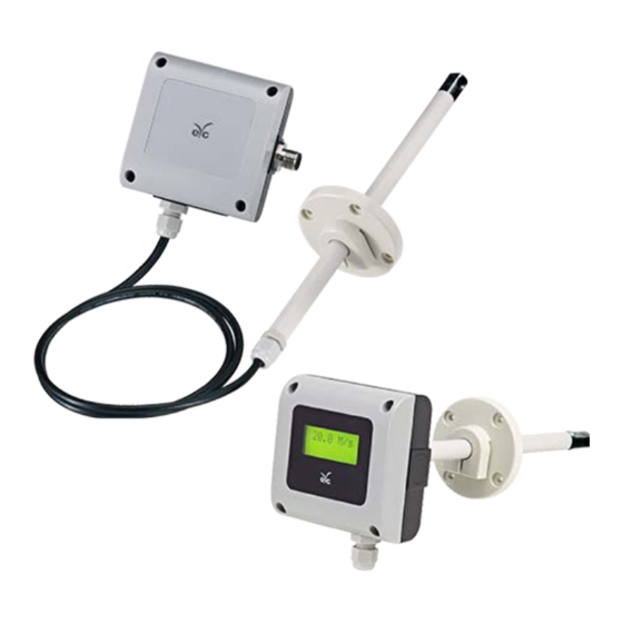
- Page 1 Operation Manual eYc FTS34/35 Thermo Air Velocity Transmitter eYc FTS34/35...
-
Page 2: Table Of Contents
Security considerations ...............P.02 II. Connection ...................P.03 Analog diagram ................P.03 RS-485diagram ................P.03 Analog + RS-485 diagram ............P.03 III. DIP Switch ....................P.04 Zero Button ...................P.05 RS-485 & Modbus ..............P.05 IV. Software and calibration operation step ..........P.05 V. Inspection and maintenance ...............P.09 www.eyc-tech.com... -
Page 3: Security Considerations
This product can not be used for any explosion-proof area. Do not use this product in a situation where human life may be affected. eYc-tech will not bear any responsibility for the results produced by the operators! Warning! Installation and wiring must be performed by qualified personnel in accordance with all applicable safety standards. -
Page 4: Connection
Air Velocity Thermo Air Velocity Transmitter II. Connection Analog diagram RS-485 diagram Analog + RS-485 diagram www.eyc-tech.com... -
Page 5: Dip Switch
Thermo Air Velocity Transmitter III. DIP Switch For FTS34/35 products, the setting status of DIP switch will be read by software while power on, and this reading action will not happen later on. Thus in order to read the DIP switch status again by software, the user must to reboot again if re-setting the DIP switch. -
Page 6: Zero Button
The user will observe the LED flashed for a few seconds for reminding the user. RS-485 & Modbus FTS34/35 integrate a RS-485 interface for digital communication as an option feature. Based on Modbus protocol makes the general convenience on PLC, HMI and PC connection. - Page 7 Open the UI, go to function "Interface", click item "Config" and then setting COM port, BAUD rate and data format, pressed "Scan" bottom for scan devices and "Scan" for connection. Select Station ID and click "CLOSE AND EXPORT” Click Apply www.eyc-tech.com...
- Page 8 6. Setting on RS-485 and offset adjustment Station ID:1 ... 247 Baud rate:9600 / 19200 / 38400 / 57600 / 115200 Data Frame:None-8Bit-1Stop / None-8Bit-2Stop / Even-8Bit-1Stop / Even-8Bit-2Stop / Odd-8Bit-1Stop / Odd-8Bit-2Stop Flow Offset adjustment Temperature Offset adjustment www.eyc-tech.com...
- Page 9 Air Velocity Thermo Air Velocity Transmitter 7. Data display and logging Flow velocity unit:[m/s], [ft/s], [km/h], [mph], [knot] Temperature unit:°C / °F Export file:*.CSV 8. Device information www.eyc-tech.com...
-
Page 10: Inspection And Maintenance
Check installed angle Refer to the section Check dust and contamination Align measurement head with flow on the sensor direction Cleaning the filter Changing the filter Calibrate Replace the sensor www.eyc-tech.com... - Page 11 Air Velocity Thermo Air Velocity Transmitter Sustainable | Green | Professional Temp. & Humid. / Dew Point / Air Velocity & Volume / Flow / Pressure Measuring Specialist Tel.:886-2-8221-2958 Web:www.eyc-tech.com e-mail:info@eyc-tech.com www.eyc-tech.com...
Need help?
Do you have a question about the FTS34 and is the answer not in the manual?
Questions and answers