Table of Contents
Troubleshooting

Subscribe to Our Youtube Channel
Related Manuals for Plura TCC70XS

Summary of Contents for Plura TCC70XS
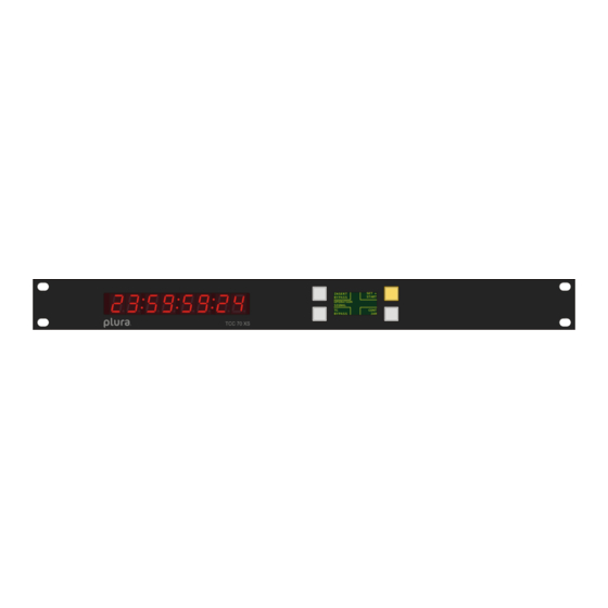
- Page 1 Installation & Operation Manual Version: 2.6 November 4, 2019 TCC70XS Integrated Time Code System Time Code Generator with Real–Time Functionality Time Code Reader and Inserter INSERT SET + BYPASS START OPERATION SIGNAL CONT BYPASS...
-
Page 3: Table Of Contents
Installation & Operation Manual TCC70XS Page 3 CONTENTS REVISION HISTORY COPYRIGHT WARRANTY ONLINE RMA UNPACKING/SHIPPING/REPACKAGING INFORMATION SAFETY INSTRUCTIONS EC DECLARATION OF CONFORMITY INTRODUCING TCC70XS OVERVIEW FRONT PANEL CONTROLS BACK PANEL CONNECTORS 1.3.1 TCC70XS (v2) 1.3.2 Previous TCC70XS SPECIFICATIONS 1.4.1 Electrical, Mechanical, and Environmental Characteristics, Others 1.4.2... - Page 4 Installation & Operation Manual TCC70XS Page 4 2.2.1 Status Monitor by Ethernet 2.2.2 Status Monitor by USB THE ETHERNET MODULE OVERVIEW OF FUNCTIONS THE INDIVIDUAL FUNCTIONS 3.2.1 Add User: Enter a New User with Password 3.2.2 Modify User: Change a Password 3.2.3...
- Page 5 5.1.1 Conversion from LTC to Video Time Code (D-VITC, ATC) 5.1.2 Conversion from Video Time Code (D-VITC, ATC) to LTC TCC70XS AS A REAL–TIME TIME CODE GENERATOR INSERT REAL–TIME & DATE 5.3.1 Real–Time & Date of the Internal Real–Time Clock 5.3.2...
- Page 6 Installation & Operation Manual TCC70XS Page 6 A1 Revision History Date Subject – Preliminary versions. February 10, 2014 First released document. February 21, 2014 • New status at page “Time and Date” of the status monitor of the 3G-Video module: “last used source”.
- Page 7 Page 7 Copyright Copyright © Plura Europe GmbH 2002-2019. All rights reserved. No part of this publication may be reproduced, translated into another language, stored in a retrieval system, or transmitted, in any form or by any means, electronic, mechanical, photocopying, recording, or otherwise without the prior written consent of Plura Europe GmbH.
- Page 8 This warranty is given by Plura with respect to this product in lieu of any other warranties, express or implied. Plura and its vendors disclaim any implied warranties of merchantability or fitness for a particular purpose.
- Page 9 Ensure that all packaging material is removed from the product and its associated components before installing the unit. Products returned to Plura for servicing or repair should have a tag attached showing: • Name and complete address of the owner and the name of the person that can be contacted.
- Page 10 Page 10 A6 Safety Instructions The general safety information in this part is for both operating and service personnel. Plura products are only to be used as directed. Specific warnings and cautions will be found throughout the manual where they apply.
- Page 11 Installation & Operation Manual TCC70XS Page 11 Injury Precautions This product includes a power supply; therefore, potentially lethal voltages are present within this product during normal operation. Observe the following precautions: WARNING: To prevent fire or shock hazard, do not expose this product to rain or moisture.
- Page 12 Installation & Operation Manual TCC70XS Page 12 Product Damage Precautions PREVENT OVERHEATING To prevent product overheating, position this product only where sufficient air circulation can be maintained. Good air circulation is essential to prevent internal heat build–up, do not block any ventilation openings. Do not expose this product to direct sun light or any other strong lights.
- Page 13 Installation & Operation Manual TCC70XS Page 13 PREVENTIVE MAINTENANCE: VISUAL INSPECTION Qualified Service Personnel Only: Visually inspect this product for signs of damage, scorched components, and loose or disconnected pin connectors. If you discover heat damaged parts, try to determine the cause of the overheating before replacing the damaged parts;...
- Page 14 Installation & Operation Manual TCC70XS Page 14 A7 EC Declaration of Conformity...
-
Page 15: Introducing Tcc70Xs
There are two different hardware configurations, the current TCC70XS (v2), built from mid- 2015, and the previous TCC70XS, built up to mid-2015. They differ in some connectors and in the standard configuration: The RS485/RS422/RS232 serial interface is optional with TCC70XS (v2). -
Page 16: Front Panel Controls
Browser (Ethernet port). Power–up messages When TCC70XS is switched on all LEDs of the 8–digit display and all lamps of the function keys will shortly light up. In the next step current firmware versions will be indicated: The 8–digit LED display indicates the firmware version of the 3G–Video module. -
Page 17: Back Panel Connectors
• 2–pole ON/OFF switch. ETHERNET RJ45 Ethernet port. You can control the complete female jack functionality of TCC70XS through this port. LINK Also, you can open a status monitor and upload and download profiles. Orange–coloured LED (LINK) lights up if connection to the Ethernet network has been established. - Page 18 VIDEO Video output, format of the video signals same as video input. Female TCC70XS is able to add data to the input signal as well as to delete data from the video input signal. T–_TxD serial interface, see below SERIAL...
-
Page 19: Previous Tcc70Xs
Installation & Operation Manual TCC70XS Page 19 1.3.2 Previous TCC70XS LTC IN LTC OUT REF / GPI SERIAL VIDEO IN LOOP OUT VIDEO OUT 10/100 BASE-T LINK Name Connector Pin Assignment/Description USB port, used with the following PC programs: Receptacle Set–Up and Software Updates... - Page 20 VIDEO Video output, format of the video signals same as video input. Female TCC70XS is able to add data to the input signal as well as to delete data from the video input signal. 10/100 RJ45 Ethernet port. You can control the complete BASE–T...
-
Page 21: Specifications
Installation & Operation Manual TCC70XS Page 21 1.4 Specifications 1.4.1 Electrical, Mechanical, and Environmental Characteristics, Others Electrical Characteristics Power consumption 16 W maximum Heat dissipation capacity 23 W maximum Mechanical Characteristics Weight Approximately 3.2 kg Dimensions Front plate 19” / 1 RU... -
Page 22: Video
Installation & Operation Manual TCC70XS Page 22 1.4.3 Video Video input VIDEO IN Format Serial digital video: • SD, according to SMPTE 259M • HD, according to SMPTE 292M • 3G, according to SMPTE 242M Connector BNC (IEC169–8), 75 ... -
Page 23: Ltc
Installation & Operation Manual TCC70XS Page 23 1.4.4 LTC Input (LTC IN) Format According to ANSI/SMPTE 12M–1–2008 Connector Balanced signals LTC_IN_A and LTC_IN_B: • Via 3–pin XLR female (according to IEC 268–1) • Via 2 pins of the 9–pin DSUB female REF/GPI... -
Page 24: Gpio, Gpo, 24 V Output
Installation & Operation Manual TCC70XS Page 24 1.4.6 GPIO, GPO, 24 V Output GPIO: GPIO_1 ... GPIO_4: Input “Low“: -2.0 to +1.0 V Input specification Input “High“: +3.0 to +24.0 V Impedance: 4.7 kΩ Frequency: 0–1 MHz GPIO_1 ... GPIO_4: Open Collector output of an NPN transistor at 4k7 pull–up... -
Page 25: Fuse Replacement Procedure
Installation & Operation Manual TCC70XS Page 25 1.5 Fuse Replacement Procedure The power plug module has a 2–pole fuse–holder incorporated, which is located between the inlet and the ON/OFF switch. To access the fuses please proceed as follows: 1. Turn power switch to off (position 2. -
Page 26: First Steps
• If you want to access TCC70XS via browser or if you want to use any other Ethernet function (SNMP, NTP server, NTP client), establish a 10/100Base–T Ethernet connection to your local network as shown above. Use a straight CAT5 cable between TCC70XS and a switch or hub. -
Page 27: Network Set-Up
“Installation”. The computer which you have to use for the network set–up must be connected to the same network as TCC70XS. If you have a firewall running, please disable it or make the UDP port 8001 available for incoming and outgoing traffic. -
Page 28: Accessing Tcc70Xs Via Browser
(please refer to chapter “Network Set–Up”). Place a direct link on your PC desktop to have an easy access to TCC70XS next time. The TCC70XS homepage offers three function modules, which can be configured and controlled: Ethernet: Configuration and status of the integrated Ethernet module. -
Page 29: Accessing Tcc70Xs Via Usb
The following PC programs are provided for the USB port: Set–Up and Status Monitor: Software Updates: Only one program can access TCC70XS at the same time, because the USB port can be opened only once. This program enables: • Software updates. -
Page 30: Helpful Tips For Configuration And Troubleshooting
TC70XS via browser: you successfully could open the TCC70XS start page. Upon shipping of TCC70XS, some basic setups of the 3G–Video module will be stored as a profile. You can load a profile and proceed to set parameters according to your individual application. -
Page 31: Verification And Troubleshooting With Status Indicators And Displays
Page 31 1.6.5.2 Verification and Troubleshooting with Status Indicators and Displays TCC70XS provides feedback to you via various status indicators and displays. This helps you to verify proper operation as well as to find faults. The 8-digit LED display: You can program the display to see either what time code currently is generated or read. - Page 32 Installation & Operation Manual TCC70XS Page 32 NTP Client: Feedback about the NTP client function will be indicated at configuration page NTP Client of the Ethernet module. Chapter: “The Ethernet Module“ → “The Individual Functions“ → “NTP Client“ NTP Server: Feedback about the NTP client function will be indicated at configuration page NTP Server of the Ethernet module.
-
Page 33: Software Update
.tcf. Update of modules “3G–Video or “Front” You have to connect the USB port of TCC70XS to your computer with a common “Type A to Type B” cable. If you first plug to the USB port a driver has to be installed. You will find the driver at the included CD. - Page 34 Installation & Operation Manual TCC70XS Page 34 3. Click Scan Frame to open the list of the modules. Choose 3G–Video or Front. 4. Select “Flash Update“ in the File menu. 4. Open the .tcf file: 3G-Video module: TCC70 3G-Video n.nn.nn.tcf Front module: TCC70 Front n.nn.nn.tcf...
- Page 35 The computer which you have to use for the update must be connected to the same network as TCC70XS. If using a firewall, ensure that the computer can connect to TCC70XS on TCP ports 20, 21, 23 and 954 and on UDP ports 123, 161 and 8001 for both incoming and outgoing traffic.
-
Page 36: Software Tools For Tcc70Xs
Click Scan Frame to open the list of those modules, which can be accessed via USB: 3G– Video and Front (previous TCC70XS models only). Choose a module and click on Configure. The program now offers tabs, which represent the configuration pages. There you can verify and change parameters. -
Page 37: Configuration By Ethernet
The following description assumes that you successfully could open the TCC70XS start page. Apart from the power supply TCC70XS includes three function modules. By Ethernet you can reach all modules to perform a set–up as well as to view status information: •... -
Page 38: Login, Login Status, Logout
“admin“. If you have passed the login, the login status indicates the username. Click button Logout if you want to logout. 2.1.2.3 Accessing the TCC70XS Function Modules Click on an item in the list at the left side: • Ethernet: Configuration and status information of the Ethernet module. -
Page 39: The Status Monitor Of The 3G-Video Module
Status Monitor by Ethernet The 3G–Video module (video and time code functions) offers a status monitor. If you have done the network set–up and if you have access to the 3G video module of TCC70XS (as Status Monitor described in chapter “First Steps”), just click the button to open the status monitor. -
Page 40: The Ethernet Module
3.1 Overview of Functions You can access the Ethernet module only by Ethernet, not by USB. Please refer to subchapter “Configuration by Ethernet“ of main chapter “Software Tools for TCC70XS” for a description of how to access the Ethernet module. -
Page 41: The Individual Functions
Installation & Operation Manual TCC70XS Page 41 3.2 The Individual Functions 3.2.1 Add User: Enter a New User with Password User Name Enter a new name. Password Create a new password. Repeat Password Repeat the password. Click on Add User to finish. -
Page 42: Version: Information About Status Of Hardware And Firmware
The buffered clock can be set in the following ways: • the first time TCC70XS receives data from a real–time reference; • the first time TCC70XS receives data from a real–time reference which indicates “lock” state; • if the internal real–time clock of the 3G-Video module is set manually;... -
Page 43: Snmp Functionality
Installation & Operation Manual TCC70XS Page 43 3.2.6 SNMP Functionality 3.2.6.1 Create a MIB File Execute on your computer. Open the Tools menu and select “Create MIB File ...”. Please follow the instructions of the “TCC70 MIB Maker”. step: Do you want to create a new... - Page 44 Installation & Operation Manual TCC70XS Page 44 step: Select the path where you want to store the MIB file. With a click on “Finish” the MIB file will be created. You will see the screen flickering, but don’t worry and don’t interrupt the process.
-
Page 45: Configuration Page "Snmp
Enter the system location string. Contact Enter the system contact string. Enable Traps The Ethernet module of TCC70XS is able to send traps to the IP address set at Trap Receiver IP. This feature can be switched on or off completely. -
Page 46: Ntp Client
3.2.7 NTP Client The NTP client functionality is used to synchronize TCC70XS with an NTP server. The NTP client queries time & date from an NTP server and sets the internal real–time clock. This kind of real–time synchronization can be uses as an alternative to an external real–time reference connected to REF/GPI connector. - Page 47 Installation & Operation Manual TCC70XS Page 47 Stratum This field indicates the stratum value received from the selected NTP server. This value tells the “distance” of the server to a reference clock. A server that is directly connected to a reference device (e.g. an atomic clock or a GPS clock or a radio clock) would have stratum 1.
-
Page 48: Ntp Server
The NTP server functionality enables TCC70XS to be used as a real–time reference by other devices (NTP clients) within the local network. TCC70XS is able to offer the network a precise real–time if a high precision external real–time reference is connected to the REF/GPI connector. Alternatively, the NTP client function can be used. - Page 49 The NTP server indicates its status at the “Stratum” and “Reference” fields. The content of these fields depends on the precision of the real–time clock. This is an internal clock of TCC70XS which is set and tuned by a real–time reference (which is either an external real–time reference at the REF/GPI connector or the NTP client).
-
Page 50: Handling A Leap Second
A real–time reference (which is either an external real–time reference at the REF/GPI connector or the NTP client) will be responsible for the accuracy of the NTP server of TCC70XS. If a leap second announcement from the real–time reference is received, a leap second alarm will be transmitted to the NTP server. -
Page 51: Ntp Status And Troubleshooting
Installation & Operation Manual TCC70XS Page 51 3.2.8.3 NTP Status and Troubleshooting The NTP server indicates its status at the “Stratum” and “Reference” fields. Refer to the following table to interpret the given information: Stratum: 0 Reference: INIT The internal real–time clock has not received any valid time update since power has turned This state sets an alarm condition in the NTP message: LI = 3 = clock not synchronized. - Page 52 Installation & Operation Manual TCC70XS Page 52 value receives an offset of “Fudge Stratum – 1“ at normal operating. The frequency and phase synchronization of the time code generator is lost. Please check the external sync signal (video, PPS, LTC).
-
Page 53: System: Name, Log File, And Ethernet Status
The device can get a name. Enter a text with 20 characters at maximum. Click button Save To Module to store this entry. This name appears wherever TCC70XS devices can be found within the local network, this helps you to identify this special device. -
Page 54: Configuration Page "Front Panel": Brightness And Screen Saver
Note: Previous TCC70XS models have a separate Front module to configure brightness and screen saver. To access it click to Front in the vertical menu on the left and then to Front Panel in the horizontal menu above. -
Page 55: The 3G-Video Module: Video And Time Code
Installation & Operation Manual TCC70XS Page 55 The 3G–Video Module: Video and Time Code 4.1 Overview of Standard Features 4.1.1 Standard Features of the Time Code Generator Sync Signal: Real-Time Handling: Video external reference: GPS, NTP Client LTC IN programming the local time zone... - Page 56 Sync = LTC Read Sync = internal TCC70XS offers status feedback at the OLED screen via four independent programmable status segments. The Gen Sync Status function for a status segment indicates the status of the phase and frequency synchronization of the time code generator, depending on the mode of sync selection: “Sync”...
-
Page 57: The Real-Time Mode Of The Time Code Generator
Internal Interface NTP Server TCC70XS expects time & date from a real–time reference. You can select between two real– time sources at the “Reference” page of a configuration tool: • External GPS or DCF77 receiver. This type of external real–time reference has to deliver the following signals: o PPS: pulse per second, TTL, connect to pin 1 of REF/GPI. -
Page 58: Handling Of A Leap Second
(please refer to “Mode of Local Time Zone Synchronisation“ at chapter “Reference: Real–Time Clock Adjustment“). 2. If the data of the real–time reference announces a leap second, TCC70XS will be able to execute the time jump simultaneously with the real–time reference if one of the following conditions applies: A: Checkbox “After Leap Second of Reference Input“... -
Page 59: Handling Of A Dst Switching
Please refer to chapter “Reference: Real–Time Clock Adjustment“. This DST switching affects signal outputs according to the example below. If TCC70XS does the DST switching of the local time zone automatically, the sequence of the generated real–time signals (time, date [day/month/year]) then will be for example:... -
Page 60: Time Code And Video Locked To A Real-Time Reference
10 MHz Receiver A high–quality GPS receiver outputs a 10 MHz signal which synchronizes the SPG. TCC70XS receives time & date as well as PPS from the GPS receiver, but the internal phase and frequency synchronization locks to the connected video signal. All units are locked, no illegal... -
Page 61: The Free Mode Of The Time Code Generator
Installation & Operation Manual TCC70XS Page 61 4.1.3 The FREE Mode of the Time Code Generator Switching on the FREE method of operating can be done utilizing a function key or GPIO assigned with the Operating Mode Free function or clicking button FREE at the Generate page of the configuration tool. -
Page 62: The Start Mode Of The Time Code Generator
Operating Mode Start function, or clicking button START at the Generate page of the configuration tool. The time addresses of the time code are determined by a free–running counter. If TCC70XS powers up with this operating mode, the generator starts with the value which has last been entered at Generator Set Time of the Generate page of the configuration tool. -
Page 63: Standard Features Of The Time Code Reader
“general reader” (Read). The following functions are only available for the “general reader”: • Jam Sync, i.e. the data transfer of the reader data to the time code generator. • Decoding the MTD data of the Plura Timer System. • Decoding a date. Overview of the basic features: Frame rate Selectable: 24, 25, 30, 30 Drop, automatic. -
Page 64: The Jam Sync Method Of Operation
Please refer to chapter “Jam: The Jam Sync Methods for details of configuration. TCC70XS offers programmable elements which can be used for a status feedback: status segments at the OLED screen, function keys with a lamp, and GPIOs. An element can receive the Jam function to give a feedback of the Jam Sync operating mode (for configuration please refer to chapter “Keys: Keys and Lamps, Status and GPIOs”). - Page 65 This method operates similar to “Single Jam”. There will be one transfer only, but unlike “Single Jam” this method keeps the JAM SYNC mode, so every time TCC70XS powers up a single transfer occurs. The transfer in this method waits until the generator reaches the Genlock, i.e.
- Page 66 (e.g. PAL to NTSC or vice versa) the original time code should be connected to the time code input and the converted video should be connected to the video input of TCC70XS. Thus, the converted time code will be synchronised to the converted video. Format...
-
Page 67: Standard Features Of The Video Channel
Installation & Operation Manual TCC70XS Page 67 4.1.7 Standard Features of the Video Channel Video channel • 8–bit, 10–bit • Bypass • ATC/D-VITC lines insert enabled/disabled • Character insert enabled/disabled Supported SD Video Standards Video Format Scanning Format Standard Frame rate, Hz 525/59.94... -
Page 68: Standard Features Of The Character Inserter
Installation & Operation Manual TCC70XS Page 68 4.1.8 Standard Features of the Character Inserter Character inserter • Four video windows selectable (time code or text) • Colour selectable • Position selectable • Size selectable • Format selectable Example of character insertion:... -
Page 69: Other Standard Features
Installation & Operation Manual TCC70XS Page 69 4.1.9 Other Standard Features 4 function keys with lamp Programmable functions 4 status segments at the OLED display Programmable functions 4 GPIOs Programmable functions Please refer to chapter: “Keys: Keys and Lamps, Status and GPIOs“. -
Page 70: The Status Monitor
Installation & Operation Manual TCC70XS Page 70 4.2 The Status Monitor Status “System“ 4.2.1... - Page 71 Installation & Operation Manual TCC70XS Page 71 TC Generator Current status of the time code generator and feedback about the current set–up: frame rate Feedback about the current frame rate: 24 / 25 / 30 / 30 df operating mode Feedback about the current operating mode: real–time...
- Page 72 (flags 1 – 6) as well as evaluated according to its meaning (bgf 0 – 2, cf, df, ff/pc). id and dir are flags produced from TCC70XS: id = 1 if VITC, = 0 otherwise, dir = 1 if LTC runs in reverse direction, = 0 otherwise.
-
Page 73: Status "Time And Date
Installation & Operation Manual TCC70XS Page 73 Status “Time and Date“ 4.2.2 Time & Date external reference: Status information about the selected real–time reference. last used source Identifies the source which has last set the internal real–time clock: none internal real–time clock has not set so far external pps + serial real–time reference at REF/GPI connector... - Page 74 Installation & Operation Manual TCC70XS Page 74 connected before = “yes“, as soon as data of the real–time reference has been received – without a check of plausibility. This status returns to “no“ every time the REAL–TIME method of operating is switched on or the source of the real–time reference or the serial protocol has changed.
-
Page 75: Troubleshooting Regarding Real-Time Reference
Basically, there are no faults if the status monitor has no field at its Time and Date page. If the real–time of TCC70XS does not match the expected time, try to find the source of the problem following the steps below: 1. - Page 76 Installation & Operation Manual TCC70XS Page 76 2. Check the generated time (local time zone), status fields Time & Date – local time zone and internal utc ➢ Fault: The generated time is completely out of tune (deviation ≥ ½ hour).
-
Page 77: Configuration
Chapter “First Steps” with its subchapters: • Browser: “Accessing TCC70XS via Browser“, • USB: “Accessing TCC70XS via USB“, and chapter “Software Tools for TCC70XS” with its subchapters: • Browser: “Configuration by Ethernet”, • USB: “Configuration by USB”. The following description assumes that you successfully managed to access the video and time code module. -
Page 78: Save To File": Store A Complete Set-Up In A File
Installation & Operation Manual TCC70XS Page 78 Configuration pages Functions and Profile are available always. At the Functions page you can adjust the states of the functions as described before. The Profile page enables to store and load a complete set–up. -
Page 79: Profile": Store And Load Setups
Installation & Operation Manual TCC70XS Page 79 “Profile”: Store and Load Setups 4.3.3 This module has a flash memory to store different setups. A complete set–up stored to the module is called a “profile”. You can identify different profiles by a number or a name. You can assign the “Load Profile”... -
Page 80: Functions": Functions Of The Module
Installation & Operation Manual TCC70XS Page 80 “Functions“: Functions of the Module 4.3.4 The configuration page Functions indicates the complete range of functions. It is possible to individually switch on or off functions. Functions via Browser Functions via USB The Edit and Use checkboxes define the state of a function:... -
Page 81: System": Name, Boot, Info, Snmp
System via USB Name You can assign a name to this module. Enter a text with 10 characters at maximum. This name appears wherever TCC70XS devices can be found, either via Browser or via USB. Cold Boot Clicking this button enables a restart of the module. At first a window appears with the message that the operation of the module will stop during restart. -
Page 82: Keys": Keys And Lamps, Status And Gpios
“Keys“: Keys and Lamps, Status and GPIOs 4.3.6 At the front panel, TCC70XS offers an OLED with programmable status segments and four illuminated keys. At the rear panel, there are four programmable GPIOs and one GPO relay contact. Basically, the functions of these in– and outputs are programmable. - Page 83 Output: Level sensitive as a lamp or a pulse with selectable pulse duration. Select from the drop–down lists. Please refer to the document “RUB AT/DT/HT/XT + TCC70XS Application: GPIO Functions” for a description of all available functions. You will find this document at the included CD.
-
Page 84: Read": Configuration Of The "General Reader
Page 84 “Read“: Configuration of the “General Reader” 4.3.7 TCC70XS is equipped with time code readers for the following time code formats: D-VITC, ATC_LTC and ATC_VITC. “Read“ is a “general reader” which receives data from the special readers listed above. The current values of this general reader can be visibly inserted in a video window and are avail- able for the Jam Sync function. - Page 85 Installation & Operation Manual TCC70XS Page 85 Priority The “general reader” can receive time code only from those readers which are enabled: the corresponding checkbox Use at configuration page Functions must be checked: LTC Read, D-VITC Read, ANC Read (+ enable reader at configuration page ANC Read).
-
Page 86: Ltc Read": Ltc Reader Functions
Installation & Operation Manual TCC70XS Page 86 “LTC Read“: LTC Reader Functions 4.3.8 TCC70XS is equipped with an LTC reader. LTC Read via Browser LTC Read via USB Frame Rate The frame rate of the LTC reader can be set automatically or can be fixed to a value. Select the appropriate function from the drop–down list. -
Page 87: D-Vitc Read": D-Vitc Reader Functions
Installation & Operation Manual TCC70XS Page 87 “D-VITC Read“: D-VITC Reader Functions 4.3.9 TCC70XS is equipped with a D-VITC reader. D-VITC Read via Browser D-VITC Read via USB Frame Rate The frame rate of the D-VITC reader can be set automatically or can be fixed to a value. -
Page 88: Anc Read": Ancillary Data Reader Functions
Installation & Operation Manual TCC70XS Page 88 4.3.10 “ANC Read“: Ancillary Data Reader Functions TCC70XS is equipped with an Ancillary Data reader. This functionality is used to read ATC (Ancillary Time Code) according to SMPTE–12M–2. ATC can be of type ATC_LTC and ATC_VITC. -
Page 89: Jam": The Jam Sync Methods
Installation & Operation Manual TCC70XS Page 89 4.3.11 “Jam“: The JAM SYNC Methods The Jam Sync method transfers time code of the “general reader” (Read) to the generator. Jam via Browser Jam via USB Mode Please refer to chapter “The JAM SYNC Method of Operation” for a detailed description. - Page 90 If TCC70XS has been switched off, the “Single Jam” method will be cleared. Single Jam can be activated by a click on this button, or by a programmed function key or a...
-
Page 91: Generate": Basic Set-Up Of The Time Code Generator
The configuration page Generate (example shows the browser view): Frame Rate Adjust the frame rate of the time code generator. If TCC70XS is used in a video application, the frame rate has to match the picture rate of the television signal:... - Page 92 Installation & Operation Manual TCC70XS Page 92 Automatic The generator can adapt its frame rate automatically. This feature is suitable for the START and JAM SYNC methods of operating, but not for REAL–TIME. No automatic mode, recommended for the REAL–TIME mode.
- Page 93 Installation & Operation Manual TCC70XS Page 93 Date+Status .DD.MM.YY] BCD coded date: Day.Month.Year [BG6/5 . BG4/3 . BG2/1]; two-digit year format. indicate a status: Bit(s) = BG7 (“Units of Hours“): If = 1: Time code transports the local time with high precision.
- Page 94 Installation & Operation Manual TCC70XS Page 94 AUXOFFS Coding of date & time offset conforming to LEITCH CSD–5300 format with Auxiliary Offset. The user data are used for the date as described under “BBC”. Additionally, an offset is encoded in 30–minute increments. 6 bits in binary form are split into two 3–bit groups and are inserted into the reserved binary groups BG5 and BG7:...
-
Page 95: Reference": Real-Time Clock Adjustment
Installation & Operation Manual TCC70XS Page 95 4.3.13 “Reference“: Real–Time Clock Adjustment TCC70XS can receive time & date from a real–time reference. The configuration page Reference (example shows the browser view): Reference Select the real–time reference and the serial protocols: Source Select the real–time reference:... - Page 96 Installation & Operation Manual TCC70XS Page 96 Time Zone and DST Mode (DST = Daylight Saving Time) Reference Input: The module uses UTC as an internal time base. The following settings and the settings Offset Reference Input at the Time Zone tab are needed to convert the data of the real–time reference input into UTC.
- Page 97 Installation & Operation Manual TCC70XS Page 97 Manual Clicking Update Now! forces a manual update with the real–time reference. All changes at this configuration page will immediately get effective – provided that the real–time reference currently delivers valid data. Mode of Local Time Zone Synchronization Periodically The internal real–time clock updates periodically with the time &...
-
Page 98: Time Zone": Time Zone Adjustment
Installation & Operation Manual TCC70XS Page 98 4.3.14 “Time Zone“: Time Zone Adjustment Select the time zone of the real–time reference and the local time zone. The configuration page Time Zone (example shows the browser view): Reference Input (DST = Daylight Saving Time) This module uses UTC as an internal time base. - Page 99 Installation & Operation Manual TCC70XS Page 99 Local Time Zone (DST = Daylight Saving Time) The time code generator operating in the REAL–TIME mode generates the local time zone. The following settings are used to calculate the local time zone from the internal UTC time base.
-
Page 100: Ltc Generate": Ltc Generator Functions
Installation & Operation Manual TCC70XS Page 100 4.3.15 “LTC Generate“: LTC Generator Functions TCC70XS can output the data of the time code generator in an LTC format. LTC Generate via Browser LTC Generate via USB Gain Select the output level from the drop–down list. -
Page 101: D-Vitc Generate": D-Vitc Generator Functions
Installation & Operation Manual TCC70XS Page 101 4.3.16 “D-VITC Generate“: D-VITC Generator Functions TCC70XS can output the data of the time code generator in a D-VITC format. D-VITC Generate via Browser D-VITC Generate via USB Line Select Mode No D-VITC will be generated. -
Page 102: Anc Generate": Ancillary Data Generator Functions
Installation & Operation Manual TCC70XS Page 102 4.3.17 “ANC Generate“: Ancillary Data Generator Functions TCC70XS includes an ancillary data generator. This functionality is used to generate ATC (Ancillary Time Code) according to SMPTE–12M–2. ATC can be of type ATC_LTC and ATC_VITC. - Page 103 Installation & Operation Manual TCC70XS Page 103 ATC: LTC/VITC Mark for Deletion Checking this box will mark all ATC data packets for deletion. The data packets are still present and at the same location, but the data content will not be evaluated anymore. The ATC reader of this module receives the data packets independent from this set–up, i.e.
- Page 104 Installation & Operation Manual TCC70XS Page 104 Locations of ATC Data Packets The preferred locations are based on the vertical interval switching point defined in SMPTE RP 168. Regarding HDTV interlaced and segmented frames video formats, the line specified for switching in the second field differs from the line in the first field. This will be considered using setups “On (Standard)“...
- Page 105 (D-VITC, ATC) will be generated, even if there is no video time code present in the incoming video. Please refer to the document “RUB AT/DT/HT/XT and TCC70XS Application: GPIO Functions” for more information about GPIO functions. You will find this document at the included CD. Alternatively, you can download it from:...
-
Page 106: Display": Configuration Of The 8-Digit Led Display
Installation & Operation Manual TCC70XS Page 106 4.3.18 “Display“: Configuration of the 8–Digit LED Display The 3G–Video module transfers data of the time code reader or time code generator to the 8– digit LED display. Display via Browser Display via USB... -
Page 107: Video": Video System And General Set-Up Of The Video Channel
Installation & Operation Manual TCC70XS Page 107 4.3.19 “Video“: Video System and General Set–Up of the Video Channel TCC70XS is equipped with a high definition serial digital video channel: 3G/HD/SD. Video via Browser Video via USB System Select the video standard: Auto Auto–detect of the video standard (recommended). -
Page 108: Insert": Set-Up Of All Video Windows
Installation & Operation Manual TCC70XS Page 108 4.3.20 “Insert“: Set–Up of all Video Windows Each video window can get an individual set–up. Up to seven windows can be visibly inserted. It is recommended to connect the video output to a video control monitor so you can verify the changes immediately. - Page 109 Installation & Operation Manual TCC70XS Page 109 Generate Data of the internal time code generator. The data contain time and user data; therefore, you are free to select any “time” or “user” format from the Format drop–down list. Identifier shows: Letter...
- Page 110 Installation & Operation Manual TCC70XS Page 110 Format Select the representation of the data from the drop–down list. The Delimiter can be selected independently to separate pairs or groups of characters. Text only This format displays no data of the selected Source, but a text which you can enter at “Pre Text“...
- Page 111 Installation & Operation Manual TCC70XS Page 111 MTD Data can be decoded out of one source, which has to be selected from MTD – Source“ at the Read function (please refer to chapter “Read: Configuration of the General Reader”). The selection at “Insert – Source“ has no effect anymore, but it is recommended to select “Read“...
- Page 112 Installation & Operation Manual TCC70XS Page 112 Character Font Select the character font from the drop–down list. The standard firmware has the following fonts provided: Font Roughly maximum Roughly maximum No. of characters No. of windows side by side one beneath the other...
- Page 113 Installation & Operation Manual TCC70XS Page 113 Change...: Select the colour of the character insertion or the background mask: Click on any of the colour boxes to use an already defined colour: “Basic color” or “Custom color”. If you want to define your own colour you can: •...
-
Page 114: Serial" Serial Interfaces For Remote Control
Page 114 4.3.21 “Serial” Serial Interfaces for Remote Control Depending on configuration the TCC70XS is equipped with a serial interface (in– and output pins at the SERIAL connector). The electrical format could be selected according to RS232 or RS422 or RS485 standard. -
Page 115: Applications
Installation & Operation Manual TCC70XS Page 115 Applications 5.1 Various Time Code Converters 5.1.1 Conversion from LTC to Video Time Code (D-VITC, ATC) Connect LTC to XLR female LTC IN. Connect a video signal to BNC VIDEO IN. BNC VIDEO OUT will output this video signal + time code. - Page 116 Installation & Operation Manual TCC70XS Page 116 Configuration page Read: Frame Rate: If the frame rate of the LTC input does not change, please fix it accordingly (= picture rate of the video signal, = frame rate of the time code generator).
- Page 117 Installation & Operation Manual TCC70XS Page 117 Configuration page D-VITC Generate: Line Select, SMPTE 12M recommendations: D-VITC in SD 625/50: line 19 (and opt. 21). D-VITC in SD 525/60: line 14 (and opt. 16). 1st Line = 2nd Line: D-VITC in one line only.
-
Page 118: Conversion From Video Time Code (D-Vitc, Atc) To Ltc
Installation & Operation Manual TCC70XS Page 118 5.1.2 Conversion from Video Time Code (D-VITC, ATC) to LTC Connect a video signal to BNC VIDEO IN. This video signal should have the video time code embedded. The XLR male connector LTC OUT outputs the generated LTC, which will be phase aligned to the video signal, and which contains the data of the video time code with frame-accurate precision. - Page 119 Installation & Operation Manual TCC70XS Page 119 Configuration page Generate: Frame Rate: If the picture rate of the video signal does not change, you can fix the frame rate of the generator – according to the picture rate of the video signal.
- Page 120 Installation & Operation Manual TCC70XS Page 120 Configuration page Keys (recommended): Status Gen Sync Status: feedback of the phase and frequency synchronization. Status segment lights up during video lock. Status segment flashes slowly during the fine trim procedure. Status segment flashes fast if video synchroni- zation is lost.
-
Page 121: Tcc70Xs As A Real-Time Time Code Generator
CET/CEST. You enter the para- meters of this time zone, now TCC70XS can calculate the UTC which will be the internal time base. Time & date of any local time zone can be generated programming the offsets from UTC. - Page 122 Installation & Operation Manual TCC70XS Page 122 Configuration page Time Zone: Reference Input: If the real–time reference does not deliver UTC, select the time zone of the reference from the Preset list and click Load, or enter the offsets manually.
- Page 123 Configuration page Video: Insert Enable: If the video output of TCC70XS is used e.g. for a video time code, but no video window should be visible, uncheck this checkbox. If you want to visibly insert a time & date for example, check this checkbox.
-
Page 124: Insert Real-Time & Date
• Real–time & date of the internal real–time clock can be visibly inserted in a video window. If TCC70XS receives valid data from a real–time reference, the internal real–time clock updates its time & date with data of the real–time reference. All necessary settings are taken at configuration pages Reference and Time Zone of the 3G–Video module. -
Page 125: Real-Time & Date Of An External Time Code Via Read
Real–Time & Date of an External Time Code via READ TCC70XS is able to read and decode real–time & date from an external time code. Please notice that an external time code cannot be accepted as a real–time reference for the time code generator. -
Page 126: Insert Mtd Timer Or Mtd Date
MTD data can include stop timers, various time zones, and a date. TCC70XS can read and decode these data. Normally MTD data will be transmitted in an LTC format of time code. This feature is independent from the method of operating of the time code generator. - Page 127 Installation & Operation Manual TCC70XS Page 127 Step 2: Configuration page Read (3G–Video module): Choose priority “High“ for LTC Read (or for the reader of that time code format which transports the MTD data), priority “Off“ for all other time code readers, “MTD –...
- Page 128 www.plurainc.com U.S.A. · Germany · U.A.E. · S. Korea...
Need help?
Do you have a question about the TCC70XS and is the answer not in the manual?
Questions and answers