Table of Contents
Advertisement
Quick Links
Advertisement
Table of Contents

Subscribe to Our Youtube Channel
Related Manuals for Eddyfi Technologies TSC PACE

Summary of Contents for Eddyfi Technologies TSC PACE
- Page 1 Getting Started with TSC PACE...
-
Page 2: Table Of Contents
Contents Overview Introducing TSC PACE PACE™ Instrument SENSU™ Probes Home Screen Job Setup Next Scan Parameters Data Screen Scanning Modes Scanning Data Data Analysis Scroll and Zoom Replay Camera Defect Sizing Field Report Page Properties System Settings System Settings Data Backup... -
Page 3: Overview
Overview Overview Introducing TSC PACE This document describes the operation and use of the PACE™ Instrument and its accompanying software. PACE™ is an advanced portable NDE tool designed to inspect metallic materials for surface breaking cracks. It is based on an inspection technique called Alternating Current Field Measurement (ACFM®) which has a proven track record in the oil and gas industry. -
Page 4: Pace™ Instrument
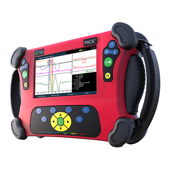
Overview PACE™ Instrument PACE™ is a portable, lightweight instrument that embodies robust, user-centric, ergonomic features; with a high-contrast toughened screen, long battery life (8+ hours) and supported by a new generation of software. It supports left and right handed use and has four secure harness attachment points. -
Page 5: Home Screen
Home Screen Home Screen The PACE™ instrument can be started by pressing the power button located on the top right of the system. The boot up sequence will take the user to the PACE™ Home screen. Figure 2 PACE™ Home Screen The top right hand corner displays hardware information, namely, the PACE™... -
Page 6: Job Setup
Home Screen Figure 3 Probe Disconnected Message When the probe is disconnected a “No Probe” message will be displayed on the top of the screen. Job Setup The Job Setup window is where the operator can set up all the information relevant to the inspection before the job begins. -
Page 7: Next Scan Parameters
Home Screen Entering Job Information Selecting any of the job parameters will open a window to add, edit or delete the selected list. Figure 5 Entering Job Information • Add new allows the operator to add new entries. • Add copy allows the operator to edit a copy of one the entries as a new entry. •... - Page 8 Home Screen The operator can cycle through the entered sub-component list as well as the pre-set weld location, scan type and scan direction lists. If the attached probe has more than one material config; these can also be chosen from this menu. If the inspection is being conducted through insulating coating, the thickness of the coating can be specified here.
-
Page 9: Data Screen
Data Screen Data Screen The data screen is the main screen for viewing and analysing the scan data. Figure 7 Data Screen The top window shows the Bx trace, the bottom window shows the Bz trace and the Top-right windows shows the butterfly plot. The bottom-right window displays page specific scan information. -
Page 10: Scanning Data
Data Screen Scanning Data To begin a live scan the operator needs to press A/C or T to select the scan direction and then the Start scan button. Alternatively, if the scan parameters need to change, the operator can press the Pause button to quick access the Next Scan Parameters window, use T to scroll through the selection and A/C to cycle through the options before pressing Start scan button to begin the scan. -
Page 11: Data Analysis
Data Analysis Data Analysis To aid in the interpretation and analysis of the ACFM data, the PACE™ instrument has a number of useful features, namely, Scroll and Zoom, Replay, Camera, Defect Sizing and Scan Report. Scroll and Zoom The Scroll and Zoom screen is where the operator can zoom and move the selected screen. Figure 10 The Zoom Function The operator can zoom in and out using F1 and F2 function buttons and scroll through the data left... -
Page 12: Camera
Data Analysis The operator can toggle the replay speed using F1 and F2 function buttons, Pause the replay using F3 and stop the replay with F4. The replay will continuously loop until stopped by the operator. Camera The camera function allows the operator to take photos of the inspection piece to be included in the report or imported separately. -
Page 13: Defect Sizing
Data Analysis Defect Sizing When a defect is found, the length and depth of it can be calculated from the Defect Sizing screen. In the screen, F3 button adds a defect zone active window to begin the procedure. Figure 13 Defect Sizing –... - Page 14 Data Analysis Figure 15 Defect Sizing - Calculating the length and depth Once the operator has the set the sizing lines, the F3 button will open the Size now screen. In Size now, the operator can input the length estimate for the defect and the software will return a calculated length and depth.
-
Page 15: Field Report
Data Analysis Field Report The field report function allows the operator to collect all the scan information (defect info, notes, probe info, photos) and creates a formatted report in pdf and word format. Navigate to F4 button “More” and select “Create/Edit Scan Report”. Figure 17 Field Report Generation Figure 18... -
Page 16: Page Properties
Data Analysis Page Properties While reviewing the scan data it is possible to view the full scan parameters from the Page Properties window. Pressing the F4 button “More” then “Page Properties” will open the window. Figure 19 Page Properties From the parameter list, operator name, scan direction, weld location, notes can be edited if required from this window. -
Page 17: System Settings
System Settings System Settings System Settings From the system settings menu it is possible to toggle the max scan time, brightness settings, timezone, day-night mode, display units and help language. Figure 20 System Settings • The max scan time sets how long an individual scan can go before the software auto-stops it, this ranges from 3 –... -
Page 18: Data Backup
System Settings Data Backup After an inspection, all the scan pages, photos and reports can be saved to a USB stick from the System Settings menu. With a USB attached, pressing the F1 button “Save Data” will save the scan files to the USB. Figure 21 Saving Data Clearing Scan Pages and Information... -
Page 19: Software Update
System Settings Software Update It is possible to update the PACE™ software to a newer version or reinstall the current version from the System Settings. With the USB stick with the PACE™ software inserted, pressing the F4 button “More” then “Update Software” will initiate the installation process. Figure 22 PACE™... -
Page 20: Troubleshooting
Troubleshooting Troubleshooting Software Crash on Start-up On instrument start-up, if the software fails to load or displays an error message, attempt to resolve the issue by restarting the instrument. If the same error occurs, it is possible to rebuild the software by pressing and holding the power button for 15 seconds. -
Page 21: Safety And Care Information
Safety and Care Information Safety and Care Information General Safety Information People with Heart Pacemaker • SENSU™ probes generate electromagnetic fields which can interfere with electronic devices (like heart pacemakers), which could cause them to malfunction. It is therefore not suited for persons with heart pacemakers. -
Page 22: Taking Care Of Your Instrument
Safety and Care Information Taking care of your instrument General care: • Do not cover the heatsink while the instrument in use. • Do not submerge the instrument or the probe in water or any other liquids. • Do not subject the instrument to magnetic fields. •... - Page 23 | 21...
- Page 24 Technical Software Consultants Ltd. (wholly owned subsidiary of Eddyfi NDT, Inc.) in the United Kingdom and/or other countries. Eddyfi Technologies reserves the right to change product offerings and specifications without notice.2018-10-11 www.tscndt.com...
Need help?
Do you have a question about the TSC PACE and is the answer not in the manual?
Questions and answers