Table of Contents
Advertisement
Quick Links
Advertisement
Table of Contents

Related Manuals for ACUTRONIC Fabian HFO


Summary of Contents for ACUTRONIC Fabian HFO
- Page 1 Vyaire Medical, Inc. Cover Sheet Title: Fabian HFO and Auxiliary Systems Part no.: 113003.EN V5.1.x 2019####, Ver.: A Print the attached pages according to the printing instructions. Do not print this page. Versions Ver. Chg. Order Description Initial release...
- Page 3 Ventilation Beyond Limits fabian HFO and Auxiliary Systems Instructions for Use, Software Version 5.1.x 113003.EN V5.1.x 2019####, Version A...
- Page 4 Disclaimer ACUTRONIC Medical Systems, assumes no responsibility for the use or reliability of its software on equipment that is not furnished by ACUTRONIC Medical Systems ACUTRONIC Medical Systems makes no warranty of any kind regarding software applications that are created by the user.
-
Page 5: Table Of Contents
Contents: Introduction ......................1 Working with the instructions ..................1 Notices and warnings....................1 Applicable product versions ..................1 Symbols ........................2 Warnings cautions and notices ................4 Always observe (fabian) ....................4 Liability for functionality ∕ damages ................7 Intended use ........................ - Page 6 4.4.3 Trend menu .......................... 30 System operation ....................34 Preparing for operation ....................34 5.1.1 Connect the power supply ....................34 5.1.2 Connect the gas supply ......................34 5.1.3 Connect the tubing set ......................35 5.1.4 Connect Nitric Oxide (NO) tubing sets ................. 36 5.1.5 (NO) Bias flow selection .......................
- Page 7 11 Accessories and options ................... 103 Accessories List ....................... 103 CO 2 monitoring......................105 11.2.1 CO 2 Sensor module types and selection ................105 11.2.2 Connect the CO 2 module to fabian HFO................107 11.2.3 MicroPod sensor module ....................109 ® 11.2.4 Respironics CO 2 sensors ....................
- Page 8 11.4.5 PRICO re-enabling cases ....................128 11.4.6 PRICO errors ........................128 FOT ......................... 130 11.5.1 Forced Oscillation Technique (FOT) at fabian HFO ............130 11.5.2 FOT general layout......................131 11.5.3 Erasing the FOT graph ....................... 132 11.5.4 FOT disabling conditions ....................132 11.5.5...
-
Page 9: Introduction
NOTE: Notes provide additional information to clarify an explanation or instruction. Applicable product versions This Instructions for Use is applicable for fabian HFO devices running software version 5.1: x, where (x) can be any number. 113003.EN V5.1.x 2019####, Version A... -
Page 10: Symbols
1 Introduction Symbols The symbols defined in this section may appear in this document and on the equipment label or labels. Symbol Description Article No. Batch code CAUTION, refer to operator’s manual for important safety information and precautions. Chemical burn warning. Dangerous voltage warning. - Page 11 1 Introduction Symbol Description Keep dry. Manufactured without the use of natural latex or derivatives. Manufacturer Marking per Medical Devices Directive 93/42/EEC. Nebulizer (Obsolete) Network Ethernet connection.(Disabled) Non-Sterile NOTE symbol Nurse Call signal output. Nurse Call signal output. Potential equalization connection. Protective Earth ground.
-
Page 12: Warnings Cautions And Notices
WARNING: Only use this ventilator in combination with an external monitoring device (for example: SpO WARNING: Only operate the ventilator with accessories recommended by ACUTRONIC Medical Systems AG. WARNING: The ventilator must be operated by qualified technical staff to ensure immediate remedial action in the event of malfunction. - Page 13 WARNING: DO NOT modify the equipment. WARNING: Before applying non-original accessories, ensure that they are biocompatible. All accessories supplied by ACUTRONIC Medical Systems for use on fabian ventilators are biocompatible. WARNING: When connected to a patient DO NOT simultaneously touch the external power supply cord and the flow sensor connector cable.
- Page 14 2 Warnings cautions and notices Symbol Description WARNING: DO NOT use the etCO module in the presence of flammable anesthetics or other flammable substances in combination with air, oxygen- enriched environments, or nitrous oxide. WARNING: Check alarm limit settings each time the etCO module is used.
-
Page 15: Liability For Functionality ∕ Damages
2 Warnings cautions and notices Maintenance The fabian HFO device is a ventilator classified as Class IIb according to the European Directive, as such: • Inspection according to manufacturer specifications is required every 12 months. Maintenance must be performed by ACUTRONIC Medical Systems trained personnel with access to •... -
Page 16: Intended Use
2 Warnings cautions and notices Intended use The fabian HFO is intended for premature infants, new-borns as well as children weighing up to 30 kg. The fabian HFO is intended for “in-patient use” in hospitals, medically-used rooms and intra-hospital patient transport. -
Page 17: System Overview
One Operating Manual (# country specific) • Contraindications Severe airflow obstruction and intracranial-hypertension would contraindicate the use of the fabian HFO neonatal and infant ventilator. In the event of ventilation for several hours or more, care must be taken for optimal conditioning of the respiratory gases (warmth, humidification) to optimize secretion mobilization and prevent damage to mucous membranes. -
Page 18: Fabian Front Connections
3 System overview fabian Front connections 3.3.1 Devices with serial number prefix AI ∕ AL External Bias Flow (FG - Fresh Gas) port and port for nCPAP system based on flow generators (single limb systems) Expiratory limb port Proximal Pressure port Inspiratory limb port/ HFO port 3.3.2 Devices with serial number prefix 20 ∕... -
Page 19: Rear Panel
3 System overview Rear panel 3.4.1 Hardware with HDMI Description Video Out HDMI connection Nebulzer & Service USB Connection Network jack for data management, PDMS (For connection to network with minimum 3 KV galvanic isolation) (DISABLED) DB9 RS-232 port for PDMS Flow Sensor 7-pin Connector Nurse Call 3-pin Connector Loudspeaker (Audio) -
Page 20: Hardware With Video In
3 System overview 3.4.2 Hardware with Video in Description Connector for 24V DC external power supply (No charging) Network jack for data management, PDMS (For connection to network with minimum 3 KV galvanic isolation) (DISABLED) USB port for data output, Software update and connection for Masimo SpO module. -
Page 21: Initial Hardware Model
3 System overview 3.4.3 Initial hardware model Description Connector for 24VDC external power supply (No charging) Network jack for data management , PDMS (for conection to netwok withi minimum 3KV galvanic isolation) (DISABLED) USB port for data output and Software update, Connection for Masimo SpO module DB9 RS-232 port for Service, CO option or PDMS... -
Page 22: General Hardware Characteristics
RS-232 : ±3 to ±15V Flow Sensor : maximum load is one Flow sensor. (Only ACUTRONIC Medical Systems Flow sensors can connect) max. Voltage: 5 V max operating current: 300 mA per hotwire -> 600 mA total. max Voltage: 5 V max operating Current: 700 mA 113003.EN V5.1.x 2019####, Version A... -
Page 23: System Functions And Displays
4 System functions and displays 4 System functions and displays Control panel options The Control Panel features two key elements: The Display (Touch screen) The Touch screen (1) allows the direct control of the ventilator parameters by pressing defined buttons on the Graphic User Interface (GUI). -
Page 24: Rotary Pulse Encoder
4 System functions and displays The keypad features two rows of buttons with various functions. Alarm Silence For acknowledging and audibly silencing alarms for a maximum duration of 120 seconds. Subsequent alarms with higher priority are visually displayed during periods of alarm silence. -
Page 25: Display Concept Structure
4 System functions and displays Display concept structure 4.2.1 Display areas The information system features two key display areas The Touch screen LED indicators 4.2.2 Display screen The display screen shows various information, setting and display areas depending on the display settings or menu. Information bar indicating: •... -
Page 26: Information Bar
4 System functions and displays 4.2.3 Information bar The Information bar displays from general information to displaying alarms. It is divided into three sections. The Information bar indicates the following among other things: Neonatal or Pediatric mode • Patient Data available •... -
Page 27: Numeric Field ∕ Alarm Limits
4 System functions and displays 4.2.4 Numeric field ∕ alarm limits In the Numeric area, all measured values are displayed together with the set limits relevant in the selected Ventilation mode. There can be multiple pages of Numeric areas. To go to the next page, press the button (1) below the Numeric area. - Page 28 4 System functions and displays The alarms can be set between the following ranges: Apnea [sec] 2 to 20, OFF (in CPAP, NCPAP, DUOPAP, SIMV, SIMV+PSV, PSV modes) CPAP [mbar] Upper limit ‒9 to 40 (in CPAP mode) Lower limit ‒10 to 39 CPAP [mbar] Upper limit...
-
Page 29: Graphics Display
4 System functions and displays 4.2.5 Graphics display Displays the current Pressure-, Volume- or Flow measurements as a diagram. Use the Graphics key to access the Graphics menu. Three waveforms are simultaneously displayed. You can also switch to Loop Display view. In this view two loops and one of three waves are displayed. -
Page 30: Ventilation Menu
4 System functions and displays Ventilation menu 4.3.1 Operation – general Push the buttons and their statuses are indicated by various colors: Light Blue: Push button. Dark Blue: focused push button. Yellow: (in Functions menu): parameters are monitored by the system. -
Page 31: Operation - Settings
4 System functions and displays 4.3.2 Operation – settings The Ventilation parameters can be set before starting ∕ activating Ventilation mode: 1. For the desired Ventilation mode, tap the key once: the key will turn Yellow. 2. The Configuration parameters for the preselected Ventilation mode can now be adjusted. -
Page 32: Ventilation Parameter Dependency
4 System functions and displays 4.3.3 Ventilation parameter dependency If parameters are mutually regulating, an arrow will appear on the parameter requiring modification indication the required direction. In this example, Pinsp is being reduced but is NOT able to be reduced further as it is limited by the PEEP setting. - Page 33 4 System functions and displays List of Locked Values Parameter Neonatal Pediatrics CPAP >10 >10 E-flow >20 Not blocked Flow >5 >5 Flow (CPAP mode) >4 >4 HFO P >25 >25 manual HFO P >20 >20 mean HFO P > 0 >20 mean HFO V...
-
Page 34: Graphics Menu
4 System functions and displays Graphics menu The Graphics menu can be accessed from the Graphics button on the Keypad. The Graphics menu The following graphics are available in the Graphics menu: Curves Curves Loops Loops Trends Trends will be loaded when pressing the Trends button Trends 113003.EN V5.1.x 2019####, Version A... -
Page 35: Curves
4 System functions and displays 4.4.1 Curves The Graphics menu shows the following curves: • Pressure • Flow Volume • When auto-scaling of graphics is switched OFF, the graph can be adjusted manually: Select desired graph. Press the graph. The selected graph is marked with the “Cursor”... - Page 36 4 System functions and displays The Freeze key stops the curve being updated. The Configuration parameters and measurements in the Display area continue being updated. The key will turn Green. Press the Freeze key again to continue updating the Curve data. Depending on the Ventilation mode selected, the Graphics menu displays the Configuration parameters and...
-
Page 37: Loops
4 System functions and displays 4.4.2 Loops The Loops menu features the following loops: • Pressure ∕ Volume (P∕ V Loop) Volume ∕ Flow (V∕ /F Loop) • The following parameters for the respective Curve can be selected in the upper area of the display: Pressure •... -
Page 38: Trend Menu
4 System functions and displays 4.4.3 Trend menu The device trending function automatically saves an average of measurements every 30 seconds. Measurements of up to five days can be recorded. Trend Data is automatically deleted in the following cases: • Date and ∕... - Page 39 4 System functions and displays Trend menu: Press Graphics (1) key Press Trends key Loading Trend data Loading Trend Data 113003.EN V5.1.x 2019####, Version A...
- Page 40 4 System functions and displays The Trend menu features three simultaneous parameters as curves. The Parameters displayed can be modified by activating the Select List on left side. Available parameters are: % MV • • mand insp • Compliance • mean •...
- Page 41 4 System functions and displays The Trend graphs can be scaled between the following ranges: %MV Mand 10 to 120 Compliance 1 to 12 [mL ∕ mbar] 10 to 5000 [mL2 ∕ sec] EtCO 10 to 160 [mmHg] 20 to 120 [%] Freq 20 to 300 [bpm] HF Ampl...
-
Page 42: System Operation
5 System operation 5 System operation Preparing for operation 5.1.1 Connect the power supply Connect the fabian with power cable to a suitable power outlet. WARNING: DO NOT connect the device to a power outlet strip. Power fluctuations from the system may trip the circuit breaker in the power outlet strip causing a power shut OFF to the device. -
Page 43: Connect The Tubing Set
5 System operation 5.1.3 Connect the tubing set WARNING: ELECTRICAL HAZARD NEVER use anti-static or electrically conductive tubes. WARNING: The pressure gradient on the fabian system of the ventilator measured on the patient connection port can increase when accessories or other components are attached to the system. -
Page 44: Connect Nitric Oxide (No) Tubing Sets
5 System operation 5.1.3.1 HFO tubing set connection for serial number prefix 20 ∕ AK ∕ AH Connection to HFO module WARNING: The HFO outlet connector must be connected with the Inspiratory limb. Connection to Expiratory limb will result in incorrect ventilation! 5.1.4 Connect Nitric Oxide (NO) tubing sets 113003.EN V5.1.x 2019####, Version A... - Page 45 5 System operation 5.1.4.1 fabian HFOi Sn’s AI ∕ AL (NO) tubing set and flow sensor connections fabian Ventilator 12 Humidifier Outlet Patient Gas Sample Line with Nafion 13 Inspiratory Breathing Circuit Tube INOvent NO System 14 Gas Sample Tee NO ∕...
- Page 46 Connect the Patient Gas Sample Line with Nafion (2) with the Gas Sample Tee (14) on the “Patient Circuit assembly”. 5.1.4.2 fabian HFO Sn’s 20 ∕ AK ∕ AH Conventional mode (NO) tubing set and flow sensor connection. 113003.EN V5.1.x 2019####, Version A...
- Page 47 11. 22F X 15M Adapter Refer to the Illustration in section “5.1.4.2: fabian HFO Sn’s 20 ∕ AK ∕ AH Conventional mode (NO) tubing set and flow sensor connection. Connect the HFO Connection Tube (21) with the NO Injector Module (7, 8, 9, 10 ,11).
- Page 48 5 System operation 5.1.4.3 fabian HFO, Sn’s 20 ∕ AK ∕ AH HFO mode ONLY (NO) tubing set and flow sensor connection. 1. Fabian HFO Ventilator 11. Inspiratory Connecting Tube 2. Patient Gas Sample Line without Nafion 12. Humidifier IN port 3.
-
Page 49: Bias Flow Selection
5 System operation Refer to the Illustration in section “5.1.4.3: fabian HFO, Sn’s 20 ∕ AK ∕ AH HFO mode ONLY (NO) tubing set and flow sensor connection. Connect the HFO Connection Tube (20) with the T-Connector Assembly (8). Connect the assembled NO Injector Module (7) to the Humidifier Inlet (12) with: •... -
Page 50: Patient Circuit Assembly
5 System operation Patient circuit assembly We recommend the use of “Single Use Patient Circuits” to be used on the device. Best performance is achieved with dual limb heated systems. Refer to the following diagram for setup: Connect the distal Inspiratory limb to Inspiration port (Insp) on the ventilator. 1.1. -
Page 51: Recommended Positioning Of Temperature Probe For Humidifier
5 System operation 5.2.1 Recommended positioning of temperature probe for humidifier One of the major sources of problems in neonatal ventilation is, that excessive rainout is affecting accuracy of flow measurement and therefore compromising its use in various modes of ventilation. We recommend carefully following the manufacturer’s instructions for use of the Humidifier to minimize the risk of rainout in the Patient Circuit. -
Page 52: Use Of Reusable Patient Circuit
5 System operation 5.2.2 Use of reusable patient circuit If Reusable patient circuits are used, they should be used with inspiratory and expiratory limb heater wire or alternatively, a water trap in the expiratory limb: Assemble the tubing as required: •... - Page 53 5 System operation • When using an Inspiratory heater, a Water Trap must be installed at the Expiratory end. NOTE: We strongly suggest using an Inspiratory and Expiratory Heated Circuit System in HFO mode. WARNING: Ensure that the Flow-sensor IS NOT exposed to excessive Humidification. 113003.EN V5.1.x 2019####, Version A...
- Page 54 5 System operation ® The Infant Flow LP patient circuit assembly is connected in accordance with the following figure • CAUTION: Always follow the manufactures instructions to ensure the correct connections for the nCPAP and Infant Flow LP systems. 113003.EN V5.1.x 2019####, Version A...
-
Page 55: Connect Ncpap Tubing Set
5 System operation 5.2.3 Connect nCPAP tubing set Preparing the nCPAP tubing system: Connect nCPAP adapter to the fabian FG ∕ nCPAP port. (REF: 153001). Connect 22 mm adapter connector to Humidifier Chamber. Connect nCPAP system Pressure measuring limb to fabian Prox port Connect nCPAP system to Humidifier Chamber. -
Page 56: Connect Flow Sensor In Niv Trigger (Optional)
5 System operation 5.2.4 Connect flow sensor in NIV trigger (optional) For details of using nCPAP systems, refer to the manufacturer operator’s manual for consumables. Preparing the nCPAP Infant Flow ∕ Infant Flow LP ∕ Inspire Tubing System Connect Flow sensor to •... - Page 57 5 System operation Switch ON the Ventilator In order to proceed, you must acknowledge that the alarm is audible, continue using the ventilator without audio alarm or shut down the ventilator. After the system test Is complete, the Calibration menu will appear. Perform Flow sensor calibration.
-
Page 58: Device Check
5 System operation Device check Always perform a Device Check before each ventilator use or after changing the patient circuit. What Target Gas Supply Attach high pressure Air and Oxygen Air and Oxygen supply hoses supply hoses to the inlets on the rear panel are correctly connected of the ventilator Connect hoses with the corresponding wall... -
Page 59: System Standby
5 System operation What Target Function Start Ventilation mode: IPPV Monitor ventilation Test parameters to ensure the Entert the following settings: values are within the I‒flow: 10 Lpm • following ranges. E‒flow: 8 Lpm • • PEEP: 5 mbar .: 20 ±2 mbar insp •... - Page 60 5 System operation Standby – stopping ∕ pausing mechnical ventilation For device pause or standby: Remove patient from ventilator. Press and hold the Start ∕ Stop button. Information bar will count down the Green dots. A menu will appear on the screen stating, “Do you want to pause ventilation for two minutes?”...
-
Page 61: System Shutdown
5 System operation System shutdown Switching OFF the fabian Remove patient from the ventilator. Power OFF any SpO or CO devices connected to the ventilator. Press and hold the ON ∕ OFF button (1) for 6 seconds. After 6 seconds, a menu will appear on the screen stating, “Do you want to shut down the device?”... -
Page 62: Emergency Shutdown
5 System operation Emergency shutdown WARNING The emergency shutdown procedure should only be used during an actual emergency. This procedure disconnects all power to the ventilator and any other devices connected to the ventilator. Before performing this procedure, ensure that the alternate ventilation method (for example: resuscitation) is present, ready and standing by. -
Page 63: Configurations Menu
6 Configurations menu 6 Configurations menu The Configuration menu can be accessed by pressing the Menu ∕ Calibration button on the keypad and selecting the Menu push button. 1. Calibration 7. Tools 2. Display 8. Information 3. Ventilation 9. PDMS (optional) 4. -
Page 64: Calibration
6 Configurations menu Calibration The Calibration screen is the first screen that comes up when the Calibration key is pressed. Then you can proceed through the menu options to select the Calibration menu again. The Calibration menu can be accessed through the Menu ∕ Calibration button on the keypad. -
Page 65: Flow Sensor Calibration
6 Configurations menu 6.1.1 Flow sensor calibration Flow sensors can be calibrated in the upper half of the Calibration menu. NOTE: Only use the Neonatal Flow sensor for this calibration. To calibrate a Neonatal Flow sensor, select the Neonatal button. NOTE: Only use the Pediatric Flow sensor for this calibration. - Page 66 6 Configurations menu If the ventilator is in a Trigger Function mode, the function is deactivated during calibration and respiration will continue in IPPV mode. First “Checking” will appear, then “Calibration running”. lines in the diagram (see illustration on the right) move from left to right, until they are centered in this diagram.
- Page 67 (during or after in-line suction, or after surfactant therapy) Flow Sensor Leakage (loose flow insert or leak) • Flow Sensor Contamination (single-use sensor recommended) • Rain-out (contact ACUTRONIC Medical Systems sales for • recommended Patient Circuits and Humidifier to prevent Rain-out) 113003.EN V5.1.x 2019####, Version A...
-
Page 68: O 2 Sensor Calibration
6 Configurations menu 6.1.2 Sensor calibration The O sensor calibration can be accessed in the Configurations menu, by pushing the O button. The O sensor is automatically calibrated when the machine starts up and every 24 hours when in use. During Calibration procedure, the FiO concentration of the fresh gas to the patient is NOT altered. -
Page 69: Etco 2 Module
6 Configurations menu 6.1.3 etCO module Refer to section “11.2: CO2 monitoring” 6.1.4 module Refer to section “11.3: SpO2 module”. Body weight You can set the patient’s body weight in Calibration menu. This setting is used to calculate and display the VTe BW [mL ∕ kg] Numeric measurement in IPPV and SIPPV modes. -
Page 70: Display
6 Configurations menu Display Adjust screen brightness, four levels. Lock Touch screen. The screen will automatically be unlocked if an alarm is triggered or the Rotary Pulse Encoder is pressed. The Touch screen automatically locks after a set time. Display Graphs as filled or regular lines. Auto scale ON ∕... -
Page 71: Touch Screen Settings
6 Configurations menu 6.3.1 Touch screen settings Lock Touch screen 1. Manual 2. After default time Also locks by holding the Rotary Pulse Encoder for three seconds. Lock is automatically cancelled in the event of an alarm or by pressing the Rotary Pulse Encoder. -
Page 72: Trend ∕ Graph Display
6 Configurations menu 6.3.2 Trend ∕ graph display Auto-scaling graphs: Curve plotting in Graphics is automatically adjusted. • • Graphs display: Filled • Not Filled • Filled Not Filled Auto-scaling trends: Trend patterns are automatically scaled. • • Trends display: •... -
Page 73: Ventilation Parameter Settings
6 Configurations menu Ventilation parameter settings Parameter Description Automatic O 21 Vol% ∕ 21 and 100 Vol.%. In cases where oxygen supply source does NOT provide 100% oxygen, this should be set to 21% only to Calibration avoid calibration at false value. NIV Leak Set either Low, Middle or High level of NIV leak compensation (≤... - Page 74 6 Configurations menu Parameter Description Alarm Delay After visual reset of alarm, the reactivation of alarm is delayed for the set time period. This avoids an immediate re-alarm in case Operational parameters have not yet stabilized. Manual Breath ON ∕ OFF. The Manual Breath in HFO mode can be used to perform Lung Recruitment Maneuver (sustained lung inflation) if clinically accepted by internal guideline.
-
Page 75: Patient Data
6 Configurations menu Patient data Entering Patient data: NOTE: Entering new Patient data will delete all Trend data. 1. Reset : Clearing the actual patient data 2. Apply : will store patient data from now 3. Change data : is used to add new patient data. -
Page 76: Date ∕ Time
6 Configurations menu Date ∕ Time NOTE: Changing the date or time will delete all Trend data. Changing the Date and Time: 1. Use the Up and Down arrows to set the date and time. 2. After the time or date has been changed, the confirmation check mark changes colors. -
Page 77: Information
6 Configurations menu Information Displays the Information screen (System Information) containing Equipment data. Service mode The Service mode is “password” protected. Service mode provides access to Nurse Call activation ∕ deactivation, etc. Only allowed when patient is NOT connected. 113003.EN V5.1.x 2019####, Version A... -
Page 78: Alarms
7 Alarms 7 Alarms Alarm limits menu Automatically sets individual alarm limits. Alarm volume (three levels). Open Log file. Display measurements with alarm limits. 113003.EN V5.1.x 2019####, Version A... -
Page 79: Automatic Alarm Limits
7 Alarms Access the Alarm Limits menu by pressing the Alarm Limits (1) button. The Alarm Limits menu allows all alarm limits to be manually or automatically adjusted. In the event of an alarm, a notice appears in the Information bar and a Bell symbol indicates the alarm cause. - Page 80 7 Alarms Upper Alarm Limit of Pressure: A breath in the range of the upper limit will reset the delay of 5 seconds. • CPAP: with a delay of 300 milliseconds in case of a manual or mechanic breath -> pressure will be •...
-
Page 81: Configurable Alarms
7 Alarms 7.1.2 Configurable alarms Following alarm limits are displayed and can be configured in the Alarm Limits menu. High SpO alarm: 2 to 99%, off • Low SpO alarm: off, 1 to 98% • High Pulse Rate alarm: 35 to 235 bpm, off •... -
Page 82: Alarm Log
7 Alarms Alarm log Switch to Alarm Limit menu. 1. Press the Show Log key to access the Alarm Overview. The Alarm List is sorted in chronological order. The parameters shown are: Time • Message • • Priority (highlighted. See: section “7.3.1: Alarms table”) 2. -
Page 83: Alarms Table
Alarm Type Cause Solution Priority Priority Acoustic audio Contact your local Acoustic audio test has alarm test System Failure ACUTRONIC Medical failed failed Systems Distributor Contact your local Cooling fan System failure Fan not moving ACUTRONIC Medical defect Systems Distributor... - Page 84 ACUTRONIC and expiration Medical Systems pressure sensor. Distributor Contact your local Voltage System failure System error ACUTRONIC Medical monitoring Systems Distributor • Change battery, No power or too less Battery defect System failure power from battery. • Check fuse. • Switch to mains supply.
- Page 85 Solution Priority Priority Calibrate O sensor and ∕ or Contact your value out of level is out of range Sensor alarms local ACUTRONIC range Medical Systems Distributor. Clean flow Water or secretion in Clean ∕ replace flow Sensor alarms sensor flow sensor sensor.
- Page 86 Connect SpO module Sensor alarms disconnected connected Replace sensor or sensor Contact your local sensor is faulty Sensor alarms ACUTRONIC Medical failure Systems Distributor. sensor is off check SpO Connect SpO sensor Sensor alarms patient or sensor to patient malfunctioning •...
- Page 87 7 Alarms Main Alarm Text Alarm Type Cause Solution Priority Priority • Check patient, • Check patient PEEP 6 mbar above connection, High PEEP Patient alarms set value for at least 15 seconds. • Check tubing. • Adjust settings • Check patient, High ETCO High ETCO Patient alarms...
- Page 88 7 Alarms Main Alarm Text Alarm Type Cause Solution Priority Priority • Check patient, • Check patient connection. Low PIP Patient alarms Leak or disconnection. • Check tubing system for leaks. • Check setting of Pinsp. Ventilator is not • Switch to mains connected to mains supply.
- Page 89 7 Alarms Main Alarm Text Alarm Type Cause Solution Priority Priority • Lung compliance • Check patient, has increased. High minute • Check ventilation Patient alarms • Resistance has volume settings. decreased. • Adjust settings • Hyperventilation. • Lung compliance has decreased.
-
Page 90: Pressure Release Behavior
7 Alarms 7.3.2 Pressure release behavior In case of detected obstruction of the breathing tubes, the ventilator alarms and also ceases gas flow to the outlet and opens the exhalation valve to reduce the pressure in the breathing circuit to ambient pressure (ZEEP). -
Page 91: Watchdog Alarms
7 Alarms If there is an audible alarm, follow these steps: Immediately start ventilation of patient with an Alternative Ventilation method Shut down the device. Report the incident to your local distributor Use the device only if it is inevitable If there is no accompanying audible alarm, follow these steps: Stop interacting with the device Prepare an alternative treatment for the patient while the device is kept under supervision... - Page 92 7 Alarms In case of an occurrence, follow these steps: Immediately start ventilation of patient with an Alternative Ventilation method Shut down the device. Report the incident to your local distributor Use the device only if it is unavoidable If a WDST 4/16/32/64 error is resolved (was only a temporary error) WDST#8 will be triggered and displayed and the device can be further used 113003.EN V5.1.x 2019####, Version A...
-
Page 93: Battery Operation
8 Battery operation 8 Battery operation The device features an Internal Battery. Battery Run Time in HFO mode on full charge: approx. 1 hour Battery Run Time in Conventional mode on full charge: approx. 2.5 hours These values may vary depending on the parameter settings. The device continuously calculates the remaining Run Time and display it in the Information bar. - Page 94 8 Battery operation Power failure In the event of a Power Failure, the device automatically switches to Battery Power without interruption. A visual and audible message is triggered. “Power Failure” This message can be confirmed with the Alarm Silence button. The device will continuously monitor the battery run time.
-
Page 95: Ventilation Parameters
9 Ventilation parameters 9 Ventilation parameters Ventilation Parameters Parameter Mode Description Backup Backup Frequency CPAP • In the event of Apnea, spontaneous breathing is stimulated after the apnea duration with a default number of mechanical breaths. Flow Sensor must be connected and activated. Backup Trigger depends on Apnea Period Setting. - Page 96 9 Ventilation parameters Ventilation Parameters Parameter Mode Description I-time Inspiratory Time • IPPV • SIPPV • SIMV SIMV + PSV • • DUOPAP • Max. Time Maximum Time Manual Breath* All modes • Manual Breath Maximum duration allowed for Manual breaths. Adjustable from 2 to 30 seconds.
- Page 97 9 Ventilation parameters Ventilation Parameters Parameter Mode Description Maximum Pressure • IPPV Maximum Inspiratory Pressure during Volume • SIPPV Guarantee. • SIMV SIMV + PSV • • Pressure Rise I-flow or Rise time IPPV • Control Allows for use of either I-flow or Rise Time-based SIPPV •...
- Page 98 9 Ventilation parameters Ventilation Parameters Parameter Mode Description Volume Guarantee • IPPV guarant This additional function controls breaths by • SIPPV volume. • SIMV SIMV + PSV • Changes in the Ventilation system are • compensated. • This ensures the patient receives a Guarantee Volume with each breath.
- Page 99 9 Ventilation parameters Parameters in HFO mode Parameter Description AMP max Maximal Amplitude in Volume Guarantee Ensure. Flow Constant Flow ∕ Bias Adjustable from 5 to 20 Lpm Default value: 8 Lpm Freq Frequency Lung Recruitment* Adjustable 5 to 20 Hz. *Optional.
-
Page 100: Ventilation Modes
10 Ventilation modes 10 Ventilation modes The ventilator is intended for the following Ventilation modes: IPPV • Intermittent Positive Pressure Ventilation SIPPV • Synchronized Intermittent Positive Pressure Ventilation SIMV • Synchronized Intermittent Mandatory Ventilation SIMV + PSV • Synchronized Intermittent Mandatory Ventilation with PSV support •... -
Page 101: Ippv
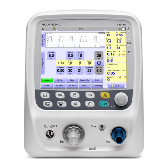
10 Ventilation modes IPPV In Intermittent Positive Pressure Ventilation (IPPV) mode Ventilation is performed at the specified patterns set on the equipment without consideration to possible spontaneous patient respiration. The Set Rate is the Delivered Rate. Set following parameters; • E‒flow Frequency (Rate) •... -
Page 102: Sippv
10 Ventilation modes SIPPV Synchronized Intermittent Positive Pressure Ventilation (SIPPV) each spontaneous patient inspiratory effort triggers a mechanical breath of the ventilator according to the ventilator parameters set for Inspiratory Period and Pressure. The number of breaths per minute supported by the ventilator is controlled by the patient. -
Page 103: Simv
10 Ventilation modes SIMV Breaths triggered by the patient will be displayed in green (default settings). Ventilation with specified pattern and frequency synchronous to the patient’s independent breathing. The patient can spontaneously breathe in between breaths but receives no pressure support. For weaning from ventilation. -
Page 104: Simv + Psv
10 Ventilation modes SIMV + PSV In Synchronized Intermittent Mandatory Ventilation + Pressure Support Ventilation (SIMV + PSV) mode, the patient can initiate a PSV breath in between the mandatory SIMV breaths. The machine breath (SIMV) is synchronized with the patient’s breathing pattern. The amount of mechanical breath per minute is same as the Preset Frequency. -
Page 105: Psv
10 Ventilation modes The Pressure Support Ventilation (PSV) option is used to support the pressure of insufficient spontaneous breathing in Triggered Ventilation modes. The breathing frequency is determined by the spontaneously breathing patient, whereas the ventilator assumes an adjustable portion of the breathing effort. -
Page 106: Ncpap ∕ Duopap
10 Ventilation modes NCPAP ∕ DUOPAP In NCPAP ∕ DUOPAP mode the patient spontaneously breathes from a mask or nasal prongs. A NIV Trigger option can be additionally implemented to provide limb modes with Breath detection (Apnea monitoring with Alarms) and triggered supported breaths (or Synchronized Transition from low to high CPAP levels) in DUOPAP. -
Page 107: O2 Therapy Mode (High And Low Flow Oxygen Therapy) Hfnc
10 Ventilation modes O2 Therapy mode (high and low flow oxygen therapy) HFNC Therapy is an option which allows use of a Continuous Flow of blended gas, between 0 to 15 LPM in NEO and 0 to 30 LPM in PED mode. Nasal Cannulas of various makes like F&P, Atom or similar can be used. -
Page 108: Special Hfo Mode Information
10 Ventilation modes Function areas and ventilation parameters. Ventilation additives. 10.9.2 Special HFO mode information When operating the device using the internal battery, HFO amplitude is limited to 60 mbar During HFO Ventilation the distinct recognition of disconnection and measurement of the Minute Volume is limited. Use of a heated Inspiratory and Expiratory Tubing system is strongly recommended in HFO mode. -
Page 109: Ventilation Additives
10 Ventilation modes Ventilation Additives To optimize Ventilation, the following additives can be combined with the selected mode. Function areas and ventilation parameters. 10.10.1 Volume limit The Volume limit function automatically switches to expiration when the default Tidal Volume is reached. Changing the ventilation pattern or adjusting the volume limit, the Tidal Volume is automatically limited. -
Page 110: Special Functions
10 Ventilation modes Special functions 10.11.1 Manual inspiration (manual Breath) In virtually all Ventilation modes, a Manual breath (with the Ventilation parameters set in the current Ventilation mode) can be triggered by pressing the Manual Inspiration button. The duration of the manual breath can be set under the Configurations •... -
Page 111: Accessories And Options
Accessories List WARNING: The items shown in this list have been approved for use with the fabian HFO ventilator. Use of non-approved items are NOT recommended and will NOT be recognized or supported by the manufacturer. If a system malfunctions with non-approved parts and ∕ or accessories, the user is responsible and liable for any and all issues associated with the system malfunction. - Page 112 11 Accessories and options Description Adapter NIST – DISS O Adapter NIST– DISS Air Masimo SpO module cable Microstream MicroPod etCO Sensor ® Capnostat 5 Mainstream etCO Sensor LoFlo Sidestream etCO Sensor 113003.EN V5.1.x 2019####, Version A...
-
Page 113: Co 2 Monitoring
NOTE: Only one module at a time can be connected and used with the ventilator. The module can be activated in the EtCO submenu of Calibration view of fabian HFO (Figure 11-1∕ Figure 11- 2). Figure 11- 2: EtCO Sensor submenu Figure 11-1: fabian HFO Calibration menu 113003.EN V5.1.x 2019####, Version A... - Page 114 11 Accessories and options To access the CO Monitoring view: Press the Graphics button (Figure 11-3) Press the EtCO button on the touch screen in the Graphics view (Figure 11-4) Graphics Button Figure 11-3: Hard key buttons Figure 11-4: Graphics view The EtCO sub view is dependent on the selected module type and discussed in section “11.2.1: CO2...
-
Page 115: Connect The Co 2 Module To Fabian Hfo
Make sure the extrusion on the 7-pin Binder Connector slots in at the bottom of the Respective Binder Connector. Fasten the connection by turning the Binder connector ring clockwise. Figure 11-7: Rear View of fabian HFO (main board 3x and higher). Arrow points towards CO port Figure 11-8: 7-Pin Binder Connector Figure 11-9: Receptacle Connector 113003.EN V5.1.x 2019####, Version A... - Page 116 Connector at the back of the fabian HFO labelled CO (Figure 11-12). Fasten the connection by turning the screws on either side of the pinned connector-clockwise Figure 11-10: Rear View of fabian HFO (Main Board 2.x). Arrow points towards CO port. Figure 11-11: 9-Pin Connector Figure 11-12: Receptacle Connector 113003.EN V5.1.x 2019####, Version A...
-
Page 117: Micropod ® Sensor Module
11 Accessories and options 11.2.3 MicroPod ® sensor module The module is designed to be incorporated into a host monitoring system. The module allows for measurement of inspired ∕expired carbon dioxide and respiration rate on patients in the Operating Room, ICU, NICU, Sedation procedures, GI, General Floor, Transport and Emergency treatment. - Page 118 11 Accessories and options The respiration rate is referred on the fabian HFO as Freq EtCO . Infrared spectroscopy is used to measure the concentration of molecules that absorb infrared light. Because the absorption is proportional to the concentration of the absorbing molecule, the concentration can be determined by comparing its absorption to that of a known standard.
- Page 119 MicroPod calibration Oridion supplies a Calibration kit (including a Calibration software CD and Calibration accessories) that enables calibration of the module on a PC. The fabian HFO displays a Calibration message that indicates on the host monitor CO screen that calibration is required at the designated interval (Figure 11-15).
- Page 120 11 Accessories and options 11.2.3.4 Basic principles for choosing Microstream Sampling lines ® When choosing Microstream CO sampling lines, the following should be considered: • The condition of the patient (ventilated or not ventilated) If the patient is ventilated, whether ventilation is humidified or non-humidified •...
- Page 121 11 Accessories and options The fabian HFO CO Monitoring View (Figure 11-17) displays real time CO data. The displayed data includes: Real time “EtCO values along with selected unit “mmHg”, “kPa” or “Vol%”. • 2“ • Respiration rate (RR) named “Freq” in breaths-per-minute (bpm).
- Page 122 Initialization time: Typically, 30 seconds, maximum 180 seconds • 11.2.3.9 System response time The system response time of the microMediCO and fabian HFO together is typically 3.1 seconds. This includes the following timing sequences: 2.7 seconds delay time • 0.2 seconds rise time from the microMediCO •...
- Page 123 11 Accessories and options SFM is triggered: During the first hour after entering measurement mode, periodically for durations of 10 seconds at a • rate which limits the total time consumed by SFMs to less than 2% of the time in which active measurements are taken.
-
Page 124: Respironics ® Co 2 Sensors
11 Accessories and options 11.2.4 Respironics ® sensors When using either of the following sensors from Respironics (Philips) you need to select the Respironics option in the EtCO menu (Figure 11-21). ® Figure 11-20: LoFlo Sidestream Figure 11-19: Capnostat 5 Mainstream EtCO Sensor EtCO... - Page 125 11 Accessories and options 11.2.4.2 Respironics module settings and information Figure 11-21: Respironics CO module In addition, the following information on the module is displayed: • The sensor state Last service date • • Sensor type 113003.EN V5.1.x 2019####, Version A...
- Page 126 11 Accessories and options The fabian HFO CO Monitoring View (Figure 11-22) displays real time CO data. The displayed data includes: Real time “EtCO “values along with selected unit “mmHg”, “kPa” or “Vol%”. • • Respiration rate (RR) named “Freq” in breaths-per-minute (bpm).
- Page 127 11 Accessories and options Several conditions could also request that a zero be performed. These requests stem from changes in the airway adapter that could indicate that the sensor is not in • optimal measuring condition. When this occurs, the airway adapter should be checked to ensure optical occlusions such as mucus have NOT obscured the adapter window.
-
Page 128: Spo 2 Module
11 Accessories and options module 11.3.1 Setting up the Masimo sensor To enable the SpO measurement, the module must be enabled. This could be done in the menu of the module. Enable SpO You can choose from the SpO menu, different module settings described in the following sections. Settings and Information 113003.EN V5.1.x 2019####, Version A... -
Page 129: Sensitivity Mode
11 Accessories and options Here is also displayed information on the sensor state and software release of the used module. You can select a sensitivity mode, a Fast SAT mode, Alarm Delay and the SpO Averaging Time. The information on the sensor state is displayed in the configuration menu, in the information bar at the bottom. -
Page 130: Alarm Delay
11 Accessories and options 11.3.4 Alarm delay You can configure the alarm delay so that transient desaturations do not give an immediate audible alarm or visual display. You can also select alarm delay settings of 0, 5, 10, and 15 seconds. Alarm delay 11.3.5 averaging time... -
Page 131: Prico
11 Accessories and options PRICO 11.4.1 General information on PRICO The USB HPLPM is a patient cable with an integral MSLP-1 Board contained in an enclosure that connects to Masimo Pulse Oximetry sensors and provides functional oxygen saturation (SpO ), pulse rate (PR), perfusion index (PI), Plethysmograph Waveforms, and other information through a serial digital interface. -
Page 132: Setting Up Prico
The following figure shows the general monitoring view. 11.4.2 Setting up PRICO PRICO can be activated in the SpO section of the Graphics menu. PRICO will adjust the FiO , to keep the SpO within the selected range. PRICO in fabian HFO 113003.EN V5.1.x 2019####, Version A... - Page 133 The higher target for SpO Range: 1 to 100%. PRICO ON ∕ OFF ON ∕ OFF switch for PRICO (touch screen softkey in fabian HFO, hard key in fabian +nCPAP evolution and fabian Therapy evolution) Dependencies on Alarm Limits: •...
- Page 134 11 Accessories and options Dependencies on each other: • “Min FiO ” must be less than “Max FiO ”. • “SpO low target” must be less than the “SpO high target”. Press the PRICO parameter on the touch screen to select. 1.1.
-
Page 135: Prico Ventilation Modes
11 Accessories and options 11.4.3 PRICO Ventilation modes PRICO is available on the fabian ventilators in the following modes: • Continuous Positive Airway Pressure (CPAP) • High and Low Flow Oxygen Therapy HFNC (O Therapy) High-Frequency Oscillation ventilation (HFO) • •... -
Page 136: Prico Disabling Alarms
11 Accessories and options 11.4.4 PRICO disabling alarms PRICO is turned OFF and cannot be re-enabled while any of the following alarms are active: Air supply pressure value out of range • • • Check ET tube Oxygen sensor defect •... - Page 137 11 Accessories and options Loss of pulse signal can occur in any of the following situations: The patient has hypotension, severe vasoconstriction, severe anemia, or hypothermia • The patient is in cardiac arrest or shock • The sensor is too tight •...
-
Page 138: Fot
11 Accessories and options 11.5.1 Forced Oscillation Technique (FOT) at fabian HFO FOT is available as a submenu under Waves ∕ loops in fabian HFO ventilators in the following modes: CPAP - Continuous Positive Airway Pressure • - High-Frequency Oscillation ventilation •... -
Page 139: Fot General Layout
11 Accessories and options The following sensors and ventilation additives can be used together with FOT: Volume Guarantee (VG) • Volume Limit (VL) • sensor • Predictive Intelligent Control of Oxygenation (PRICO) • The following option is disabled during the FOT recruitment ∕ derecruitment maneuver: •... -
Page 140: Erasing The Fot Graph
11 Accessories and options Step size information field: The pressure difference between two consecutive FOT measurements. It is automatically calculated out of the difference between the low and high-pressure settings and FOT. Information field: Depending on the status of FOT it displays if it is OFF; the remaining time of the stabilization period;... -
Page 141: Fot Procedure
11 Accessories and options Any system failure: Checksum conductor PIC • Input pressure blender • Checksum monitor PIC Low physical memory • • COM interface parallel interface • • • Cooling fan defect • Safety relay defect • DIO interface •... - Page 142 11 Accessories and options Set the three adjustable parameters (FOT , low and high-pressure settings) according to the steps needs (FOT contains a recruitment and a derecruitment phase starting at the set low pressure level and turning back at the high-pressure level). 4.1.
- Page 143 11 Accessories and options The following graphs illustrate a complete FOT maneuver in real time showing pressure levels in FOT Conventional mode with the following settings and how the results are displayed: IPPV settings FOT settings PEEP Pinsp PEEPlow PEEPhigh FOTsteps Step 6 mbar...
- Page 144 11 Accessories and options The following graph illustrates how a complete FOT maneuver looks in real time regarding pressure levels in HFO mode with the following settings: HFO settings FOT settings PEEP PEEP PEEP step insp high steps 10 mbar 15 mbar 5 mbar 14 mbar...
-
Page 145: Fot Specifications
11 Accessories and options 11.5.6 FOT specifications Fixed parameters Amplitude (∆P) of forced oscillation 5 mbar maximum 18 seconds (if the conditions are good, it is period shorter) 3 seconds out of it is the FOT measurement ∕ data collection time Frequency of forced oscillation 10 Hz I:E ratio of forced oscillation... -
Page 146: Ventilator Service And Maintenance Intervals
• Membrane HFO module sensor • Maintenance and safety inspections must be performed by ACUTRONIC Medical Systems trained personnel with access to suitable testing and measuring equipment. Maintenance Interval Indicator. The symbol will appear in the Information bar 30 days before the next maintenance has to be performed. -
Page 147: Sterilization ∕ Cleaning ∕ Disinfection
13 Sterilization ∕ cleaning ∕ disinfection 13 Sterilization ∕ cleaning ∕ disinfection • The device must be prepared after each patient treatment. Cleaning and disinfection procedures must be performed according to country specific • regulations. WARNING: The device must NOT be sterilized under any circumstances. Flow Sensor •... - Page 148 13 Sterilization ∕ cleaning ∕ disinfection Membrane holder without Membrane CYCLE 2: 1. Set for 4 preconditioning pulses 2. Steam cycle for 3 minutes at 135°C. 3. Dry cycle for 30 minutes NOTE: Change the Membrane holder after 30 uses or when the unit fails the device check – Function Test.
-
Page 149: Setting Ranges And Parameters
14 Setting ranges and parameters 14 Setting ranges and parameters Mode IPPV SIPPV Neonatal Pediatric Neonatal Pediatric Parameter E–flow [Lpm] E–time [sec] Flush Time [sec] Frequency (Rate) [1 ∕ min] I–flow [Lpm] I–time [sec] Man. Breath Time [sec] Flush PEEP [mbar] [mbar] insp... - Page 150 14 Setting ranges and parameters Mode SIMV SIMV+PSV Neonatal Pediatric Neonatal Pediatric Parameter E–flow [Lpm] E–time [sec] Flush Time [sec] Frequency (Rate) [1 ∕ min] I–flow [Lpm] I–time [sec] Man. Breath Time [sec] Flush PEEP [mbar] (backup) [mbar] insp Pmax [mbar] [mbar] PSV termination criterium [%]...
- Page 151 14 Setting ranges and parameters Mode CPAP Neonatal Pediatric Neonatal Pediatric Parameter Backup [mbar] Backup Rate [mbar] CPAP [mbar] E–flow [Lpm] E–time [sec] Flow [Lpm] Flush Time [sec] Frequency (Rate) [1 ∕ min] I–flow [Lpm] I–time [sec] Man, Breath Time [sec] Flush [mbar]...
- Page 152 14 Setting ranges and parameters Mode Neonatal Pediatric Parameter [mbar] Flow (constant ∕ bias) [Lpm] Freq [1 ∕ hr.] Hfamp [mbar] HFreq [Hz] Ratio I‒time [sec] Flush [mbar] manual [mbar] mean [mbar] mean [mL] guarant When powering the device by internal battery HFO amplitude is limited to 60 mbar. Mode Therapy NCPAP...
-
Page 153: Guide To Volume Guarantee
15 Guide to volume guarantee 15 Guide to volume guarantee Mechanical Ventilation is required to manage Neonates with severe Respiratory Failure. Pressure-limited Ventilation (PLV), delivering a fixed Peak Inflating Pressure (PIP), has traditionally been used to control the arterial Carbon dioxide (PaCO ). -
Page 154: Initial Settings
15 Guide to volume guarantee Initial settings I–flow : 8 LPM E–flow : 6 LPM Rate : between 35 to 40 BPM Inspiratory Time : between 0.3 to 0.4 seconds Pinsp : between 16 to 18 mbar PEEP : 4 to 6 mbar How to start the VG function Step 1 Setup Ventilator in SIPPV and start ventilation. - Page 155 15 Guide to volume guarantee Step 3 Set in the Pmax area, the maximal pressure value to which the VG function can regulate. Triggered and non-triggered breaths are independently supported based on lung compliance. Normally, a triggered breath has a lower Pinsp than a non-triggered one due to different lung compliance. 113003.EN V5.1.x 2019####, Version A...
- Page 156 15 Guide to volume guarantee Step 4 VG can now be activated by selecting the ON ∕OFF button. When VG function is ON, this button will turn Green. A line will appear in the Pressure Wave diagram to mark the Pmax. 113003.EN V5.1.x 2019####, Version A...
- Page 157 15 Guide to volume guarantee NOTE: If the Targeted Volume cannot be reached with the set P , the Warning: “Vte not reached ∕ check settings” will appear. An upward pointing arrow will appear in the “P ” area to indicate the maximum pressure has been reached.
-
Page 158: Setting Up The Ventilator Psv+Vg
15 Guide to volume guarantee Setting up the ventilator PSV+VG If Volume Guarantee is added to PSV, the Ventilator automatically is adjusting the PPSV level necessary to maintain the preset Target Volume. In case of an Apnea, the Ventilator will start cycling at a preset rate and PBackup. -
Page 159: Special Procedures
16 Special procedures 16 Special procedures Use of closed suction systems Suction can be performed in the following Ventilation modes: CPAP • • IPPV • • • SIMV SIMV+PSV • • SIPPV The suction catheter system must be placed between the Flow sensor and the patient. (See the following picture). -
Page 160: Technical Specifications
17 Technical specifications 17 Technical specifications Ambient conditions During operation: 10 to 40°C (50 to 104 °F) • Temperature 70 to 106 kPa • Air Pressure 10 to 90%, non-condensing • Relative Humidity During storage and transportation: –20 to 60°C (–4 to 140 °F) •... -
Page 161: Measuring
17 Technical specifications Apnea Alarm Alarm: If no breathing activity is recognized Measuring Airway measurement Range: –10 to 125 mbar Precision: ±4% Resolution: 0.1 to 1 mbar Breath volume measurement Range: 0 to 999 mL (BTPS) (inspiratory and expiratory) Precision: ±8% Resolution: 0.1 to 100 mL... -
Page 162: Resistance Values
17 Technical specifications Resolution: 0.1 to 1 mL ∕ mbar Resistance Range: 0 to 5000 mbar ∕ Lps Precision: ±8% Resolution: 0.1 mbar ∕ Lps Overdistension Index C20 ∕ C Range: 0 to 5 Resolution: Resistance values System Resistance at 30 Lpm <20 mbar ∕... -
Page 163: Dimensions ∕ Weight
17 Technical specifications Dimensions ∕ weight W x H x D 30 cm x 37 cm x 42 cm Weight ≈ 20 kg with HFO module ≈ 14 kg without HFO module Ratings Device Fuse T 1.25A L 250V Internal Battery 16.8 V 4500 mAh max. -
Page 164: Data Storage
17 Technical specifications Data storage Alarms Maximum: 1.000 messages. Maximum: 10 Log Files. Log is stored during power failure. When Log capacity is reached index, is shifted and oldest log file deleted. Trend Maximum: 5 days. Storage: every 30 seconds. Applied parts Applied parts for the device are as follows: EtCO... - Page 165 17 Technical specifications Internal Gas Blending function of the fabian HFO Proportional Gas Blending Assembly Ventilator Manifold 1. Air 29 to 87 psi 10. O Sensor Block 1. Manifold Block 2. Oxygen 29 to 87 psi 2. Manifold PCB 11. O Sensor 3.
-
Page 166: Acoustic Energy
17 Technical specifications Acoustic Energy 01.9.6.2.1.101 TABLE: Acoustic Energy VBS used fabian HFO — Accessories Patient set — Humidifier (water level) : — Test lung Part No. 1116 — Ventilator settings Acc. to TAB, 201.105 mid column — Measurement Sound Pressure... -
Page 167: Electromagnetic Compatibility Statement
(for example: Resuscitation Bag). Guideline and Manufacturer Declaration – Electromagnetic Emissions The fabian HFO device is intended for operation in the environment described below. The customer or operator of the fabian HFO apparatus should ensure it is operated in this type of environment. - Page 168 18 Electromagnetic compatibility statement Guideline and Manufacturer Declaration – Electromagnetic Immunity The fabian HFO device is intended for operation in the environment described below. The customer or operator of the fabian HFO apparatus should ensure it is operated in this type of environment.
- Page 169 18 Electromagnetic compatibility statement Guideline and Manufacturer Declaration – Electromagnetic Immunity The fabian HFO device is intended for operation in the environment described below. The customer or operator of the fabian HFO apparatus should ensure it is operated in this type of environment.
- Page 170 A study of the location should be conducted to determine the electromagnetic environment regarding stationary transmitters. If the area intensity at the location where the fabian HFO is used exceeds the above compliance levels, fabian HFO should be monitored for proper function. If unusual performance characteristics are observed, additional measures could be required, as for example: changing the direction or location of the fabian HFO.
- Page 171 The operator of the fabian HFO can help avoid electromagnetic interference by maintaining the minimum distance between portable and mobile HF telecommunication devices (transmitters) and the device fabian HFO – depending on the output rating of the communication device, as listed below.
-
Page 172: Appendix A: Glossary
Appendix A: Glossary Appendix A: Glossary Term Definition Apnea Temporary inability to breath. Atelectasis The collapse or closure of a lung resulting in reduced or absent gas exchange. Audible Able to be heard. Bias Flow The continuous flow of gas responsible for replenishing oxygen and removing carbon dioxide (CO ) from the patient circuit. - Page 173 Appendix A: Glossary Term Definition Fraction of Inspired Oxygen. A fraction of oxygen in the volume being measured. FRAM Ferroelectric Random-Access Memory. FilterLine Recognition Safeguard Generator Patient attachment for delivering CPAP, used with nasal prongs and mask. HDMI High Definition Multimedia Interface pronounced I-squared-C, is a synchronous, multi-master, multi-slave, packet switched, single-ended, serial computer bus invented in 1982 by Philips Semiconductor.
- Page 174 Appendix A: Glossary Term Definition Resistance The opposition to flow caused by the forces of friction. It is defined as the ratio of driving pressure to the rate of air flow. Resistance to flow in the airways depends on whether the flow is laminar or turbulent, on the dimensions of the airway, and on the viscosity of the gas.
-
Page 175: Appendix B: Index
Appendix B: Index Appendix B: Index CPAP, 8, 20, 24, 25, 27, 50, 72, 87, 88, 92, 97, 98, 99, 127, 130, 134, 143, 144, 151, 165 accuracy, 43, 118, 119, 152 Acoustic Energy, 158 Adapter, 116 Data storag, 156 airway adapter type, 118 Date ∕... - Page 176 Appendix B: Index HFO, i, 7, 8, 9, 10, 15, 18, 20, 25, 27, 41, 45, 66, 72, Main Board 2x, 108 85, 88, 90, 91, 92, 99, 100, 102, 105, 107, 108, 110, Main Board 3x, 107 111, 113, 114, 118, 124, 125, 127, 130, 134, 136, Manual inspiration, 102 138, 144, 151, 153, 154, 155, 158, 159, 160, 161, Masimo sensor, 120...
- Page 177 Appendix B: Index Oxygen sensor, 128, 157 Flow, 2, 8, 9, 10, 11, 12, 13, 14, 21, 22, 27, 29, 35, 41, 44, 45, 48, 49, 50, 56, 57, 59, 65, 66, 87, 89, 91, 92, 96, 97, 98, 99, 101, 102, 109, 114, 127, 128, 130, 132, 133, 138, 139, 141, 144, 145, 150, Parameter 151, 152, 154, 156, 157, 164...
- Page 178 Appendix B: Index Chemical burn, 2 Dangerous voltage, 2 Zeroing, 118, 119 Fire hazard, 2 warnings, 1 113003.EN V5.1.x 2019####, Version A...
Need help?
Do you have a question about the Fabian HFO and is the answer not in the manual?
Questions and answers