
Related Manuals for Clarke Air CAT73

Summary of Contents for Clarke Air CAT73
- Page 1 AIR/HYDRAULIC RIVETER MODEL NO: CAT73 PART NO: 3110765 OPERATING & MAINTENANCE INSTRUCTIONS GC0215...
-
Page 2: Operating Principle
INTRODUCTION Thank you for purchasing this CLARKE Air Riveter. Before attempting to use this product, please read this manual thoroughly and follow the instructions carefully. In doing so you will ensure the safety of yourself and that of others around you, and you can look forward to your purchase giving you long and satisfactory service. -
Page 3: General Safety Rules
GENERAL SAFETY RULES CAUTION: FAILURE TO FOLLOW THESE PRECAUTIONS COULD RESULT IN PERSONAL INJURY, AND/OR DAMAGE TO PROPERTY. WORK ENVIRONMENT 1. Keep the work area clean and tidy. 2. Dress appropriately - Do not wear loose clothing or jewellery. Tie long hair out of the way. - Page 4 • Moving to another work area. • Passing the tool to another person. • Never use the tool if it is defective or operating abnormally. 13. This tool should be serviced at regular intervals by qualified service personnel. 14. Avoid damaging the tool by applying excessive force of any kind. 15.
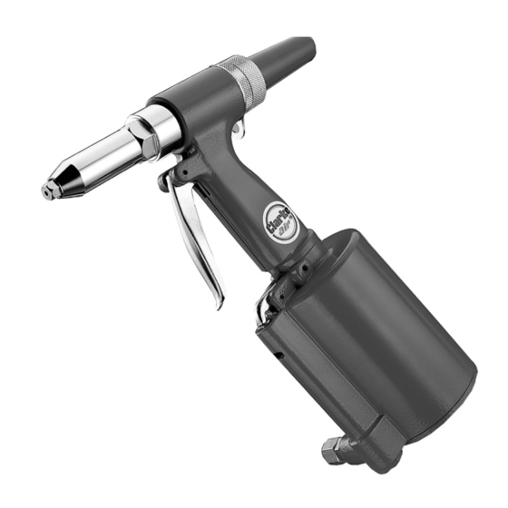
- Page 5 OVERVIEW NO DESCRIPTION NO DESCRIPTION Nosepiece Spanner Gauge Safety Cap Trigger Air Cylinder Spanner Air Inlet Connection The CAT73 Air Riveter is supplied with 4 riveting nose pieces to accept 2.4mm, 3.2mm, 4mm and 4.8mm rivets. The tool has hardened steel jaw assembly and a rivet stem safety cap, and is suitable for both aluminium and steel rivets.
-
Page 6: Compressed Air Requirements
• A typical air line layout is shown above. If an automatic in-line filter/ regulator is used, it will keep the tool in good condition, but should be regularly checked & topped up with oil. Clarke air-line oil should be used, and the lubricator adjusted to approx 2 drops per minute. -
Page 7: Before Use
6. Your air tool is now ready for use. You can fit a whip hose with a quick fit coupling if required (available from your Clarke dealer). Parts & Service: 020 8988 7400 / E-mail: Parts@clarkeinternational.com or Service@clarkeinternational.com... -
Page 8: Preparation & Adjustment
PREPARATION & ADJUSTMENT CHECKING THE OIL LEVEL 1. Disconnect the riveter from the air line. 2. Hold upside-down and remove the air cylinder cap (fig 1) with the spanner provided. 3. Remove the air/hydraulic piston assembly (grip the exposed nut and pull up) as in Fig 2. -
Page 9: Changing Jaws
5. If necessary, adjust the stroke as follows: • Hold the rear jaw case (fig. 6) with the larger spanner and loosen the lock nut with the spanner/gauge. • Adjust the stroke by rotating the jaw case assembly and tighten the lock nut when adjustment is complete. - Page 10 DISCONNECTING THE AIR SUPPLY Do not disconnect the air supply hose until the compressor has been shut down and the compressed air released. 1. Refer to the compressor instruction manual for the procedure to shut down and release the compressed air. 2.
-
Page 11: Maintenance
You may prefer to take the tool to your Clarke dealer if internal maintenance is required. Your Clarke air tool has been designed to give long and trouble free service. If, however, having followed the instructions in this booklet carefully, you encounter problems, take the unit to your local Clarke dealer. -
Page 12: Specification
STORAGE If the tool is to be stored, or is idle for longer than 24 hours, run a few drops of Clarke air-line oil into the air inlet, and depress the trigger in order to lubricate the internal parts. When not in use, disconnect from air supply, clean and store in a safe, dry place. -
Page 13: Parts Diagram
PARTS DIAGRAM Parts & Service: 020 8988 7400 / E-mail: Parts@clarkeinternational.com or Service@clarkeinternational.com... -
Page 14: Parts List
PARTS LIST Description Description Nosepiece (4.8mm - 3/16”) Rubber Cushion Nosepiece (4mm - 5/32”) Air Cylinder Nosepiece (3.2mm - 1/8”) 30-1 Air Piston Stem Nosepiece (2.4mm - 3/32”) 30-2 Air Piston A1 06-1 Jaw Case Front End 30-3 Air Piston Locknut 06-2 Jaw Case End 30-4... -
Page 15: Declaration Of Conformity
DECLARATION OF CONFORMITY Parts & Service: 020 8988 7400 / E-mail: Parts@clarkeinternational.com or Service@clarkeinternational.com...
Need help?
Do you have a question about the Air CAT73 and is the answer not in the manual?
Questions and answers