
Subscribe to Our Youtube Channel
Related Manuals for Gamma Vacuum Digitel MPC 635941


Summary of Contents for Gamma Vacuum Digitel MPC 635941
- Page 1 Digitel MPC Technician's Manual Part Number: 500000, Revision: J Gamma Vacuum, LLC Copyright © 2003 Gamma Vacuum, LLC 12912 Ventura Court No. 28 Shakopee, MN 55379...
-
Page 2: Table Of Contents
I. Contents Introduction............................6 Description.............................. 6 MPC Configurations ........................... 6 RS-232/422/485 Serial Interface......................6 Set Points ............................6 High Voltage Modules........................7 Analog Outputs ........................... 7 SAFE-CONN™ High-Voltage interlock .................... 7 AUTORUN™ ............................. 7 Remote TSP/NEG Control Option...................... 7 High-Voltage/TSP Filament Interlock Option..................8 Specifications............................ - Page 3 MPC Components..........................54 Maintenance Procedures ........................54 Removing the Top Cover........................55 Cleaning the Chassis ......................... 55 Cleaning the Fan Filter........................55 Replacing Fuses ..........................55 Input and Output Voltage Selection...................... 56 Input Voltage Selection Procedure ....................56 Output Voltage Selection Procedure....................57 Voltage Polarity Configuration......................
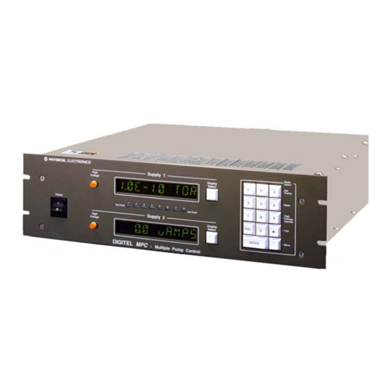
- Page 4 II. Figures Figure I-1. Photograph of the Digitel MPC....................6 Figure I-2. Remote TSP/NEG Control Option..................8 Figure II-1. MPC Rear Panel HV and SAFECONN Connectors............11 Figure II-2. Remote TSP/NEG Control Connections................12 Figure II-3. Diagram of Remote TSP/NEG Control................12 Figure II-4.
- Page 5 III. Tables Table I-1. Specifications DIGITEL MPC....................9 Table II-1. High Voltage and SAFE-CONN Connectors................ 11 Table III-1. Front Panel Controls and Indicators..................16 Table III-2. Program Mode Select Keys....................21 Table III-3. Menu Hierarchical System....................30 Table III-4.
-
Page 6: Introduction
I. Introduction The manual is divided into five sections. Section 1 contains a brief description and specifications of the DIGITEL™ Multiple Pump Control (MPC). Sections 2 (page 10) and 3 (page 15) explain the installation and operation procedures, respectively. Section 4 (page 52) provides information for servicing the unit. -
Page 7: High Voltage Modules
High Voltage Modules The DIGITEL MPC is available with two high-voltage (HV) modules: • The medium HV module has a starting capacity of 200W, 100 mA. It is intended to fully operate pumps from 10 l/s to 200 l/s and can be used on larger pumps if they are well roughed or if under high vacuum. -
Page 8: High-Voltage/Tsp Filament Interlock Option
• control cable from the DIGITEL MPC to the Remote TSP/NEG Control • high-current cable from the Remote TSP/NEG Control to the TSP/NEG • an AC input power cable Figure I-2. Remote TSP/NEG Control Option. High-Voltage/TSP Filament Interlock Option The remote interlock allows disabling of either the high voltage outputs or TSP filament firing. The interlock is installed at J506 (on the back panel of the MPC) if the option is installed. -
Page 9: Specifications
Specifications Table I-1. Specifications DIGITEL MPC. Parameter Specification Operating temperature 0 to 40°C. Operating humidity 0 to 80% RH (non-condensing). Storage temperature -20 to 70°C. Dimensions: WxHxD: 483 mm (19") x 133mm (5.25") x 476 mm (18.75"). DIGITEL MPC WxHxD: 138 mm (5.4") x 292 mm (11.5") x 219 mm (8.6"). Remote TSP/NEG Input power 115 VAC, 230 VAC, or 208 VAC selectable. -
Page 10: Ii. Installation
The procedures provided in Sections 2 and 5 of this manual and in other Gamma Vacuum, LLC product manuals must be followed to ensure that these protections are not impaired in any way. -
Page 11: Procedure
1. 3-wire, detachable AC input power cable (included with DIGITEL) 2. high voltage (HV) cable for each pump (ordered separately) 3. safety ground cable for each pump (ordered separately) Procedure Perform the following procedure to install the MPC: 1. Place the unit in its location and secure as necessary. 2. -
Page 12: Required Items
DANGER: Voltages up to 7000V are present in the DIGITEL MPC. Turn off power and disconnect AC input power cable before installing the Remote TSP/NEG Control option. Figure II-2 shows an overview of the Remote TSP/NEG Control connections in the system. filament feedthrough CONTROL control... -
Page 13: Safe-Conn™ Installation On An Ion Pump
Figure II-4. High Current Cable. 5. Connect the AC input power cable to the Remote TSP/NEG Control unit. 6. Reconnect the AC input power cable to the DIGITEL MPC. NOTE: If you need to connect a high current cable to the TSP/NEG unit, see Section 4, Connecting a High Current Cable to TSP/NEG. - Page 14 Figure II-6. SAFECONN Installation Diagram #2. 4.2. Using the plastic cylinder, keep a constant steady pressure on the SS ring, while keeping the installation tool, SS ring, and plastic cylinder assembly together. 4.3. Raise the assembly to the HVFT, and with a light tap on the plastic cylinder, slide SS ring #2 into the open groove of the PEEK cylinder.
-
Page 15: Iii. Operation
III. Operation Operation of the DIGITEL™ Multiple Pump Control (MPC) can be controlled by the operator through the system computer software. Refer to the system operator’s guide for specific operating procedures. Section 3 (page 15), Operation, contains the following information for manual control of the DIGITEL MPC. - Page 16 Table III-1. Front Panel Controls and Indicators. Control Description Main Power switch Turns main power on and off (1 = ON; 0 = OFF). High Voltage indicators When high voltage (HV) is enabled to supply 1 or supply 2, the associated indicator on the front panel lights.
-
Page 17: Rear Panel Description
Rear Panel Description Figure III-2 identifies the rear panel connectors on the DIGITEL™ MPC. Connector pinouts are given in the tables below. SafeConn connect - supply 1 HV connect - supply 1 J112 INTFC J112 J505 INTFC TSP/NEG CTRL J501 J505 J401 J104... -
Page 18: Operating The Ion Pump
J112 SER INTFC (a 9-pin, female Sub-D connector) routes the serial interface signals for the four serial interface protocols – RS-232, PHI (Physical Electronics), RS-485, and RS-422. RS-232 Operation PHI Operation RS-485 Operation RS-422 Operation –TX –TX –RX –RX Operating the Ion Pump Ensure that the pump has been installed according to instructions supplied with it. -
Page 19: Using The Controls
2.2. To turn supply 2 on (or off), press the bottom Display Select key to toggle to the desired value. 3. Press the ENTER key. NOTE: If you turn a supply ON and have not set the pump size for that supply, the display automatically goes to PUMP SIZE menu to allow you to set the value. - Page 20 Mode Select Points Bake High Voltage Operate ENTER Menu Figure III-4. Keypad. The Menu key (Figure III-5 and Table III-3), which is the blank key, is a hierarchical system for setting unit parameters and preferences. Refer to section 3, Menu Key (page 29) for information on how to use these keys.
-
Page 21: Program Mode Keys
Program Mode Keys During normal operation, you can press the 3, 6, 9, or ← key to select their program mode (Set Points, Bake, High Voltage Operate, and TSP, respectively). Press the ESC key anytime you want to exit a program mode without saving changes, or press ENTER to save the changes. Mode Select Points... - Page 22 Set Points With this feature, you can establish set point parameters: the set point number, what supply it should monitor (whether it should monitor a bakeout), and the on/off pressure values. With each set point parameter, if the set point has been used before, the present values are displayed. Procedure 1.
- Page 23 Once the set point parameters have been saved, they are immediately applied. When pressure goes below the specified set point pressure, the set point is energized lighting the associated front panel LED. If it is above the pressure, the set point is de-energized (LED off). To disable a set point If you want to disable a set point, 1.
- Page 24 Supply 1 START TIME Set Point Set Point Supply 2 6. When the display asks you to CONFIRM, press ENTER to save your bake parameters or ESC to exit without saving changes. After you have finished Once the delayed bake is enabled, the display flashes "BAKE OK" for 1 second every 5 seconds. Once the bake is started, the display flashes "BAKE nn.nH"...
- Page 25 4. To turn supply 1 on (or off), press the top Display Select key to toggle to the desired value. To turn supply 2 on (or off), press the bottom Display Select key to toggle to the desired value. 5. Press the ENTER key. NOTE: If you turn a supply ON and have not set the pump size for that supply, the display automatically goes to PUMP SIZE menu to allow you to set the value.
- Page 26 1.1. ACTIVE: Go to setup parameter 1 to specify the filament you want to fire first. 1.2. ON TIME. Go to setup parameter 3 to specify amounts of time the TSP fires. 1.3. SUBLEVEL. Go to setup parameter 4 to select watts/amps and specify its value. 2.
- Page 27 if the display reads ARMED 4, there are four cycles left and once a cycle is completed, the number decreases to three. To turn the TSP OFF, press Menu to cycle to OFF. Then press ENTER. Supply 1 TSP SETUP Set Point Set Point Supply 2...
- Page 28 2. An arrow points to the bottom Display Select key to show it is active. Press it to cycle through the options: F1 ACTIVE, F2 ACTIVE, F3 ACTIVE, F4 ACTIVE. 3. When you reach the desired filament, press ENTER to save your selection or press ESC to exit without saving changes.
-
Page 29: Menu Key
1. Press ENTER. An arrow points to the top Display Select key to show it is active. Press it to toggle between AMPS and WATTS. Supply 1 press to toggle Display Select between options Options: AMPS - AMPS arrow shows - WATTS Set Point Set Point... - Page 30 Operate Menu 1. Press Menu to step through each top menu selection. 2. Use the ENTER key to step to a sub menu. 3. Then use Menu to step through each submenu selection. 4. Press ESC to step back up to the top menu. Table III-3.
- Page 31 Note: If an attempt is made to start a pump and the pump size is not specified, this menu option is automatically brought up and displayed. You must then set the pump size in order to start the pump. 1. After you press Menu, the top display shows PUMP1 SIZE. 2.
- Page 32 You can specify the default pressure units to display: Torr, mbar, or Pascal. The bottom display shows the units presently in use. NOTE: This procedure does not change set point or TSP pressure values. For example, if you have 1.5 mbar and change to Torr, then you have 1.5 Torr. 1.
- Page 33 • BAUD RATE • SET CLOCK • SPLY1 SIZE • SPLY2 SIZE • PUMP1 CAL FACTOR • PUMP2 CAL FACTOR • SUPPLY1 KV • SUPPLY2 KV • PRM FACTOR Press ESC to exit the submenu and return to CONFIG. Mode Select Points Supply 1...
- Page 34 POWER-LOSS RESTART You can choose yes or no to have both pumps start automatically after a power loss. 1. Press the Menu key to cycle through the menu until you reach CONFIG. 2. Press ENTER to step to the submenu and press the Menu key to cycle to POWER- LOSS.
- Page 35 Supply 1 Display Options: Select BAUD RATE - 9600 arrow shows - 4800 bottom key is active Set Point Set Point - 2400 Supply 2 - 1200 Display press to cycle Select 9600 - 300 through options 5. When you reach the desired option, press ENTER to save your selection. SET CLOCK You can set the time and date of the clock.
- Page 36 SPLY1 SIZE / SPLY2 SIZE To display the supply option installed (large, medium or none) for supply 1 and supply 2, use the following procedure. 1. Press the Menu key to cycle through the menu until you reach CONFIG. 2. Press ENTER to step to the submenu and press the Menu key to cycle to SPLY1 SIZE.
- Page 37 4. Press the Menu key twice to select SUPPLY2 KV, and press ENTER. The bottom display shows the voltage strapped to supply 2. PRM FACTOR To display what line voltage the DIGITEL MPC is set to, you need to specify it — 120 or 240. Use the following procedure.
- Page 38 Mode Select Points Supply 1 Display Bake Select DIAGNOSTCS 1) Press MENU.until you Top menu High Voltage reach DIAGNOSTCS Operate Set Point Set Point 2) Press ENTER. ENTER Menu 3) Press MENU to cycle through the options, - REVISION - ERROR CODE Supply 1 - DISPLY/KEY Display...
- Page 39 ERROR CODE Table III-4 provides a list of error codes and their meanings. Here is how you get there. 1. From DIAGNOSTCS, press ENTER to step to its submenu. 2. Press the Menu key to cycle to ERROR CODE. 3. Press ENTER. Display 1 shows the last error code for pump 1.
- Page 40 Supply 1 Display Select KEY TEST Set Point Set Point Supply 2 Display Select ESC LAST 5. As you press each key to test it (press the ESC key last), the key is displayed on the bottom display. Some keys are displayed as they are. Other keys (the ENTER key for example) are displayed as symbols.
-
Page 41: Display Messages
RST DFLTS allows you to clear supply calibration, disable all setpoints, and reset pump cal factor to zero. 1. From DIAGNOSTCS, press ENTER to step to its submenu. 2. Press Menu to cycle to RST DFLTS. 3. Press ENTER to display RESET DEFAULTS. 4. -
Page 42: Front Panel Display Of Events
Front Panel Display of Events Each event is displayed in five parts (Table III-6). Each part files the dual 10 character display. Table III-6. The Five Parts of the Event Record. Part Format Description EVNT n > e is the event number PMP n ee <... -
Page 43: Analog Outputs
Analog Outputs Two analog outputs (voltage and current/pressure) from each high voltage (HV) supply are provided at J104 SET PT ANALOG OUT, a 37-pin SUB-D connector on the rear panel of the DIGITEL MPC. Voltage measuring HV supply outputs 1 and 2 provide 0 to 10 volt signals with a scale factor of 1V/1000V output voltage. -
Page 44: High Voltage/Tsp Filament Interlock Option
High Voltage/TSP Filament Interlock Option The remote interlock allows disabling of the high voltage outputs or TSP filament firing (if TSP option is installed). The interlock is installed at J506 (on the back panel of the MPC) if the option is installed. Figure III-11. -
Page 45: Specifics
3. When a device recognizes its address, it decodes the message and returns an acknowledgement to the computer, along with any data that was requested. Specifics The serial communications port settings such as number of data/start/stop bits, parity, etc. are defined in (Table I-1. - Page 46 Table III-7. Serial Command Packet Description. Field Size Comment 1. START character 1 character (byte) ASCII character is ‘~’ (TILDA) Start is the first byte in the command packet and tells remote units to start decoding a message. It should be implemented as a #define, so that it can be changed if necessary.
- Page 47 is reset back to MONITOR. Once a command packet is received, the mode changes to RESPOND. The only way the unit can get to a RESPOND is by receiving 2.1. a valid PHI start character followed by a space, 2.2. a 2-byte hex value matching the unit's address followed by a space, 2.3.
- Page 48 Table III-8. Serial Response Packet Description. Field Size Comment 1. ADDRESS of unit 2 hex characters Range 00 through FF This field is filled in with the hexadecimal representation of the integer address of the unit. The range provides 255 unique addresses for PHI controls. The controlling computer will use this field to determine that the correct remote unit is responding.
- Page 49 Table III-9. RS-232/422/485 Commands — PHI Standard Serial Interface. Description MODEL NUMBER. A description of the unit. Response: DIGITEL MPC . VERSION. Firmware revision level. Response: FIRMWARE X.X .n where X.X is the numerical revision level for major changes and n is an alpha character for minor changes. READ CURRENT.
- Page 50 DEGAS. A maintenance tool. that conditions your filaments. Each filament is fired once. DEGAS uses the specified ON TIME and SUBLEVEL setup parameters, but starts its firing at half the value. For example, if current is specified at 50 amps and time at 30 seconds, then the TSP fires at 25A for the first 15 sec and then steps up to 50A for the remaining 15 sec.
- Page 51 CRC Checksum Error The following is an example of the CRC checksum calculation. 1. The response from the DIGITEL MPC to command 01 is: 00 OK 00 DIGITEL MPC DC 2. Table III-8 gives the values of the response. 3. Add all values in Table III-10 to get 4DCh 4.
-
Page 52: Iv. Service
1-952-445-7615 WARNING: Performing any service tasks other than those described in this section without the assistance of Gamma Vacuum, LLC Customer Service could result in serious injury, could damage equipment, and may nullify applicable equipment warranties. WARNING: Service procedures are for use by qualified and authorized personnel who have experience working with voltages greater than 50 volts. - Page 53 WARNING: Do not disconnect the high voltage cable with power on. After turning power off, allow at least one minute before disconnecting electrical equipment. Do not operate the control without a proper electrical ground or near water. The control may be damaged and its safety reduced, if operated outside of its specifications.
-
Page 54: Mpc Components
MPC Components The location of MPC components are found in Figure IV-1. Table IV-1 provides their part numbers. Figure IV-1. Location of MPC Components. Table IV-1. MPC Component Parts List. Component Part Number Component Part Number Display Board 635347 100 mA transformer 635452 HV amber lamps 611716... -
Page 55: Removing The Top Cover
Table IV-2. Routine Maintenance Schedule. Maintenance Period Clean the chassis interior every six months Clean the air filter every six months Replace lamps as necessary Replace fuses as necessary Removing the Top Cover Turn off power and disconnect power cord from the DIGITEL MPC. To gain access to the unit interior, remove the nine screws securing the top cover to the chassis. -
Page 56: Input And Output Voltage Selection
Table IV-3. Part Numbers (p/n) — Fuses on the AC Power Board. F3 – Supply 1 F4 – Supply 2 F1 and F2 – Main Power F5 – Aux Power 100/120 2.5A, 250V, slo-blo, IEC, sheet 5 10A, 250V, 2.5A, 250V, 100 mA p/n 639627 slo-blo... -
Page 57: Output Voltage Selection Procedure
2. On the AC Power board (Figure IV-3), remove the cover from the two fuses (F3 for supply 1 and F4 for supply 2) and replace the fuses according to the Table IV-4. Table IV-4. Input Voltage Conversion Fuse Values for the DIGITEL MPC. F3/F4 —... -
Page 58: Prom Change Procedure
2. Remove the chassis top cover. 3. Disconnect any cables connected to the High Voltage (HV) board and remove it from its slot. NOTE: Each HV board can be independently configured for positive or negative polarity. Figure IV-4. Voltage Polarity — Location of Components. 4. - Page 59 If you need to update the revision level of the MPC, you need to change this PROM. Use the following procedure. WARNING: Voltages up to 7000V are present in the DIGITEL MPC. Turn off power and disconnect power cord before performing any service procedures. 1.
-
Page 60: Rear Panel Connector Pinouts
Rear Panel Connector Pinouts The location of the rear panel connectors on the DIGITEL MPC are shown in the Figure IV-6. Figure IV-6. Rear Panel Connectors. Connector pinouts and signal designations are provided in the following tables: • J104 SET PT ANALOG OUT — Table IV-6 •... -
Page 61: Connector J505 - Remote Tsp/Neg Control Signals
Connector J505 — Remote TSP/NEG Control Signals J505 TSP/NEG CTRL (a 15-pin, female Sub-D connector) provides the control signals for the Remote TSP/NEG Control. Table IV-7. Connector J505 Pinouts. Signal Signal Signal Current Sense COM SCR Trig Out K2 Coil SCR Trig Pull-up K3 Coil Not Used... -
Page 62: Serial Communication Protocol Selection
Serial Communication Protocol Selection Four serial interface protocols are available on the MPC — RS-232 Operation, RS-485 Operation, RS-422 Operation, and PHI Operation. Set DIP switches SW1 and SW2 on the CPU board (Figure IV-7) to select a serial interface. Table IV-9 shows the DIP switch settings. Figure IV-7. - Page 63 Table IV-9. Serial Interface DIP Switch Setting. RS-232 J112 SER INTFC Close 5 thru 8 Close 6 Signal Pin No. Signal Pin No. Open 1 thru 4 Open all others RS-485 J112 SER INTFC Close 1, 2, and 4 Signal Pin No.
-
Page 64: Remote Tsp/Neg Control Option
Remote TSP/NEG Control Option WARNING: High voltages are present in the Remote TSP/NEG Control and DIGITEL. Turn off power and disconnect power cords from both units before servicing. Figure IV-8. Remote TSP/NEG Control — Location of Components. Removing the Panels of the Remote TSP/NEG Control The Remote TSP/NEG Control has a top panel and two end panels 1. -
Page 65: Input Voltage Selection Of The Remote Tsp/Neg Control
2. Remove the end panels: 2.1. Remove the four screws (two on each side) from the end panel and pull it away from the unit. Input Voltage Selection of the Remote TSP/NEG Control To change input voltage on the Remote TSP/NEG, you need to access the bottom circuit card inside the unit. -
Page 66: Accessory Equipment
Accessory Equipment Table IV-10. Optional Accessory Equipment. Order No. High Voltage Modules 640574 medium HV module (200W, 100mA), transformer, and fuse. 635465 large HV module (1000W, 500mA), transformer, and fuse. Remote TSP/NEG Control Unit 640697 Remote TSP. (Order TSP control and power cables separately.) Ion Pump High Voltage Cables for use with 3-Million Series Captorr Pumps 642453 3 m bakeable (200°), SAFE-CONN ion pump HV cable. -
Page 67: Menu Flowcharts
V. Appendix A This appendix contains drawings/parts lists and schematics for the DIGITEL™ Multiple Pump Control (MPC) to assist qualified and authorized service technicians with on-site troubleshooting. Table V-1 lists assembly drawings (each drawing is followed by its parts list). Table V-2 lists schematics.
Need help?
Do you have a question about the Digitel MPC 635941 and is the answer not in the manual?
Questions and answers