Table of Contents
Advertisement
Quick Links
Advertisement
Table of Contents

Related Manuals for TELEDYNE API 452


Summary of Contents for TELEDYNE API 452
- Page 1 MODEL 452 PROCESS OZONE SENSOR User Manual ©2018Teledyne API (TAPI) www.teledyne-api.com 9970 Carroll Canyon Road San Diego, CA 92131-1106 Toll free: 800-324-5190 Phone: +1 858-657-9800 Fax: +1 858-657-9816 mail: api-sales@teledyne.com Copyright 2018 02852G DCN8011 Teledyne API 26 October 2018...
- Page 3 Teledyne API Model 452 Ozone Sensor User Manual, 02852G DCN8011 SAFETY MESSAGES NOTE The only user-serviceable part in the Model 452 is the lamp, which can be adjusted or replaced; however, the cautionary safety measures provided in this manual must be followed. For all other service, call TAPI Technical Support.
-
Page 4: Notice Of Copyright
Teledyne API Model 452 Ozone Sensor User Manual, 02852G DCN8011 Notice of Copyright © 2015-2018 Teledyne Advanced Pollution Instrumentation. All rights reserved. Revisions to this Manual are intended to clarify existing descriptions and are not intended to infer any changes to customers under copy exact requirements. -
Page 5: Table Of Contents
Teledyne API Model 452 Ozone Sensor User Manual, 02852G DCN8011 TABLE OF CONTENTS SAFETY MESSAGES ............................. I NOTICE OF COPYRIGHT .......................... II TRADEMARKS ............................. II TABLE OF CONTENTS..........................III LIST OF FIGURES ............................IV LIST OF TABLES ............................IV WARRANTY POLICY ..........................V 1 PRODUCT DESCRIPTIONS ........................ - Page 6 Teledyne API Model 452 Ozone Sensor User Manual, 02852G DCN8011 LIST OF FIGURES 2-1: M 452 H .................. 2-1 IGURE ODEL URITY ZONE ENSOR 2-2: P ) ..............2-3 IGURE RESSURE ROP VS URITY ERSION 4-1: E ......................4-1 IGURE...
-
Page 7: Warranty Policy
Product Return All units or components returned to Teledyne API should be properly packed for handling and returned freight prepaid to the nearest designated Service Center. After the repair, the equipment will be returned, freight prepaid. -
Page 9: Product Descriptions
The Model 452 can be used as a full flow process sensor or as a sensor to monitor a small flow of gas diverted from a process stream. -
Page 11: Specifications
Teledyne API Model 452 Ozone Sensor User Manual, 02852G DCN8011 2 Specifications Note: All specifications contained herein are subject to change without notice. Please contact Teledyne API to obtain the current specifications. 2.1 Mechanical Specifications Figure 2-1: Model 452 High Purity Ozone Sensor Weight: 2.8 lbs. -
Page 12: Performance Specifications
Teledyne API Model 452 Ozone Sensor User Manual, 02852G DCN8011 2.2 Performance Specifications Accuracy: ±1% of Full Scale. Repeatability: 1% of Full Scale Response Time: 2 sec. to 95% Zero Drift: 1% Full Scale/month (non –cumulative) 2.3 Operating Limits Measurement Range:... -
Page 13: Pressure Drop
Teledyne API Model 452 Ozone Sensor User Manual, 02852G DCN8011 2.7 Pressure Drop Figure 2-2 below shows the approximate pressure drop from the inlet fitting to the outlet fitting as a function of volumetric flow rate. Figure 2-2: Pressure Drop vs. Flow (High Purity Version) -
Page 15: Theory Of Operation
The detection of ozone molecules is based on absorption of 254 nm UV light due to an internal electronic resonance of the O molecule. The Model 452 uses a mercury lamp constructed so that a large majority of the light emitted is at the 254 nm wavelength. Light from the lamp shines through an absorption cell through which the sample gas being measured is passed. -
Page 17: Installation
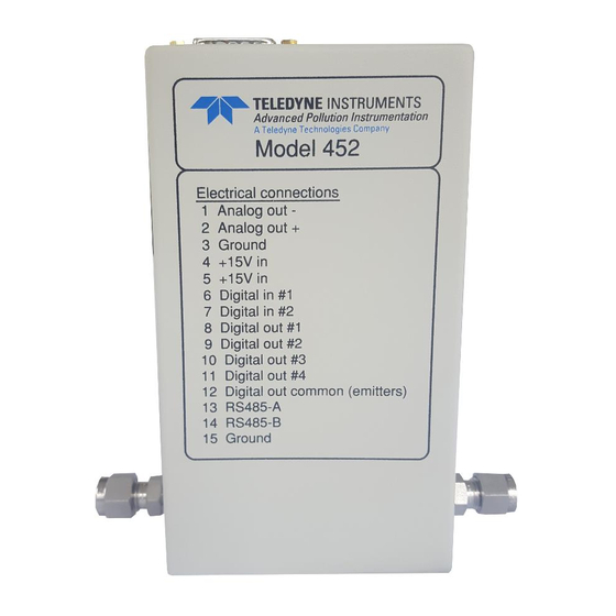
Model 452 susceptible to electrical interference from external sources. 4.3 Electrical Connections Electrical connections are made to the Model 452 using the 15 pin D-Sub connector on the top of the device. Figure 4-1 shows the pin-out of the 15-pin connector and typical connections. -
Page 18: Power Supply
Teledyne API Model 452 Ozone Sensor User Manual, 02852G DCN8011 4.3.1 Power Supply The Model 452 requires a +15 VDC power source capable of supplying 1.0 A. DC power can be connected through the male DB-15 connector or through the coaxial power jack. The coaxial power jack is configured so that the ground connection is on the outside (shield) and the +15V connection is on the center pin. -
Page 19: Status Outputs
Figure 4-2: Digital Output Connections 4.3.5 RS232/485 Interface The Model 452 features a bi-directional digital serial interface that can be used for sensor control and data acquisition. Please contact Teledyne API for documentation on the use of the RS232/485 interface. -
Page 20: Gas Connections
1. Verify that the proper electrical connections have been made (See Section 4.3) and apply power to the Model 452. Allow the Model 452 to warm up for at least 15 minutes. 2. Purge the Model 452 with zero gas (usually oxygen) at a minimum flow rate of 0.1 SLPM for at least 2 minutes. -
Page 21: Maintenance
Teledyne API Model 452 Ozone Sensor User Manual, 02852G DCN8011 5 Maintenance The only user-serviceable part in the Model 452 is the lamp, which can be adjusted or replaced. For all other service, contact TAPI Technical Support. WARNING High voltages exist inside the sensor. Use caution when sensor cover is removed. -
Page 22: Figure 5-1. Cover Assembly Screws
Teledyne API Model 452 Ozone Sensor User Manual, 02852G DCN8011 Figure 5-1. Cover Assembly Screws Figure 5-2. UV Lamp Orientation... -
Page 23: Figure 5-3. Voltage Adjustment Locations
Teledyne API Model 452 Ozone Sensor User Manual, 02852G DCN8011 Figure 5-3. Voltage Adjustment Locations... -
Page 24: Measuring And Adjusting Uv Lamp Reference And Measurement Voltages
Teledyne API Model 452 Ozone Sensor User Manual, 02852G DCN8011 5.1.1 Measuring and Adjusting UV Lamp Reference and Measurement Voltages 1. Flush the analyzer with zero gas to exhaust any possible residual high concentration of O 2. Remove the analyzer from the equipment (if necessary) to access the cover screws and the internal components of the analyzer. -
Page 25: Replacing The Lamp
Teledyne API Model 452 Ozone Sensor User Manual, 02852G DCN8011 1. Monitor the DC Voltage from GND J9 pin 1 to TP 5 (Figure 5-3). This voltage must read between –0.8 and –1.8 Vdc. If the voltage does not read correctly, loosen the two UV lamp retaining screws (Figure 5-2) and rotate the UV lamp (avoid touching the transformer on the UV lamp power supply) until this voltage (-.8 to -1.8 Vdc) is reached and then tighten the... - Page 26 Teledyne API Model 452 Ozone Sensor User Manual, 02852G DCN8011 Apply +15VDC Power to J10 (+15 VDC Power Jack) or through DB-15 connector (Figure 5-3). Allow the new lamp and analyzer to warm up for at least 15 minutes. Check the DC Voltage from GND J9 pin 1 to TP 5 (Figure 5-3). This voltage must read between –0.8 and –1.8Vdc.
-
Page 27: Sensor And System Troubleshooting
The Status LED labeled ‘CPU STATUS’ is used to verify the status of the CPU inside the Model 452. This LED should blink on and off continuously while the sensor is on. If this LED stops blinking while power is applied to the sensor, a CPU failure is indicated. -
Page 28: Sensor O.k
The normal state for the Sensor O.K. output in ON. During the warm-up period on start-up this output will stay off until the UV lamp reaches a minimum intensity. If this output remains off after the 15 minute warm-up period, or goes off during normal operation, then the Model 452 is in need of servicing. -
Page 29: Cell Dirty
Teledyne API Model 452 Ozone Sensor User Manual, 02852G DCN8011 6.6 Cell Dirty The normal state for the Cell Dirty output is OFF. If this output turns on, then the ratio of the measure detector to the reference detector (at zero) is < 0.5. This value is calculated when the zero calibration is performed.
Need help?
Do you have a question about the 452 and is the answer not in the manual?
Questions and answers