Advertisement
DIGITAL THERMATIC FAN SWITCH - PART # 0444
WARNING:
INSTALLATION OF THERMAL SWITCH
1. The Switch should be mounted in the engine bay, adjacent to the
radiator using the self-tapping screws provided. Please keep unit
away from high heat sources, such as exhaust manifolds etc.
DIGITAL THERMATIC SWITCH
Jumper
Pin
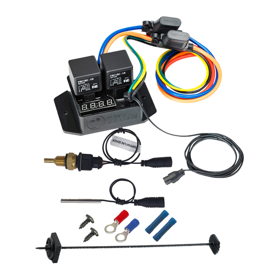
Kit Contents:
Controller x 1 – Mount Kit x 1 – Scotch Lock x 1 – Ring Terminal
(Yellow) x 1 – Self Tap Screw x 2 – Connector (Yellow) x 1
2. Select the temperature sensor mounting location before installing
the fan (if applicable). Temperature Sensor Probe installation
requires access to both sides of the radiator. Remove the radiator
and/or condenser, if necessary, to allow access to both sides.
3. For optimum performance, install the Temperature Sensor in the
radiator fin section as close to the hot coolant inlet as possible.
Select a position that will not interfere with the fan.
Temperature Sensor probe
radiator core as this will affect the Switch's operation.
DO NOT INSTALL THE SENSOR IN THE RADIATOR
HOSE, SERIOUS DAMAGE WILL RESULT!
4. Remove quick fit mount rod, button and foam pad and then
remove backing paper from foam pad. Slide foam pad onto the
quick mount rod so the pad adheres to the under face of the head
of the quick mount rod.
5. Gently separate the radiator fins in area where you propose to
mount/insert the temperature sensor probe, using the quick mount
rod or similar so as not to not damage the tubes. Insert the quick
mount rod through the separated fins along with the Temperature
Sensor probe (as illustrated). Push the locking button and Sensor
onto the quick mount. Align and insert into the separated fins,
pushing locking button onto the quick fit mount to sit flush with
the face of the radiator. Cut off excess quick mount rod.
THIS DIGITAL THERMATIC SWITCH IS FOR 12V USAGE ONLY!
Temperature
LED
Set Button
Display
MUST NOT
extend through the
77 Taras Avenue
P.O. Box 363
Altona North, Vic 3025 Australia
Phone: +61(0)3 9369 1234
Fax: +61(0)3 9369 3456
info
E-mail:
Web: www.daviescraig.com.au
Wiring Diagrams: Please refer to the wiring diagram overleaf for
installation of this Thermatic Switch. The wiring diagrams found in the
Davies, Craig range of Thermatic Fan Kits are for use with the Mechanical
Thermal Switch only.
WARNING: Do not use the vehicle's engine management system or
wiring connected to the management system as an ignition source as
it may cause failure of the management system and/or the electrical
system. The ignition source must be a steady positive supply of 12-
Relay
14VDC.
Mounting
Holes
SETTING THE ADJUSTABLE THERMATIC SWITCH
1. Set the air temperature to the maximum 110C by holding down
the Temperature Set Button
2. Start the engine and allow the engine temperature to reach ¾ on
the temperature gauge scale. This temperature should be more
than the normal operating temperature of the engine or the fan (s)
will run more than necessary
3. Immediately hold down the Temperature Set Button until the Fan
#1 runs and then turns off noting the temp at which the fan turns
off. Then reset the target temp to 1 degree (C) less than the turn
off temp. The Fan #2 (if applicable) will start 10 seconds after
Fan #1 runs.
4. The fans will operate until the air temperature is reduced by 1
degrees (C) from the set temperature.
5. After road testing, monitoring the engine temperature, if
necessary, adjust the Set Temperature to suit your requirements.
The
6. To convert temperature reading from Centigrade to Fahrenheit,
simply remove the plastic cover from the Jumper Pins by hand.
NOTE: Check that the fan(s) face the correct direction. On the hub
of Davies, Craig fans there is a message "This side must face the
front of the vehicle".
Check that the fan(s) rotate in the correct direction, which is in the
direction of the arrow on the hub. If the fans rotate in the wrong
direction swap the two leads to the fan motor.
Engine coolant under system pressure boils at 118C.
If you are in any doubt about any of these instructions consult your
retailer or DAVIES, CRAIG direct on +61 (3) 9369-1234 or
info@daviescraig.com.au
FAILURE TO COMPLY WITH THESE INSTRUCTIONS OR
TAMPERING WITH THE PRODUCT MAY INVALIDATE THE
MANUFACTURER'S WARRANTY.
WARRANTY: Davies Craig Pty Ltd hereby guarantees this product for a
period of 2 years from the date of purchase. DCPL shall replace your
Electronic Thermal Switch, if a fault develops, providing such a fault is
directly attributable to a defect in workmanship or materials used in the
manufacture of the Electronic Thermal Switch. Labour and consequential
costs are excluded.
Register Warranty at:
www.daviescraig.com.au
@daviescraig.com.au
P/No. 10957
Advertisement
Table of Contents


Need help?
Do you have a question about the 0444 and is the answer not in the manual?
Questions and answers
davies 0444 controller is new just installed and it wont light up the digital readout
The Davies Craig 0444 controller may not light up the digital readout after installation due to the following reasons:
1. Incorrect Power Source – The controller requires a steady positive supply of 12-14VDC. If the power source is unstable or incorrect, the unit may not function.
2. Faulty Wiring – If the wiring is not properly connected according to the installation diagram, the controller may not receive power.
3. High-Heat Exposure – If the unit is mounted near high heat sources like the exhaust manifold, it may malfunction.
4. Engine Management System Interference – If the controller is connected to the vehicle’s engine management system wiring, it may cause failures and prevent the display from lighting up.
Checking these factors and ensuring proper installation should resolve the issue.
This answer is automatically generated