Table of Contents
Advertisement
Quick Links
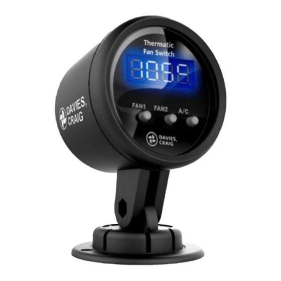
DIGITAL GAUGE THERMATIC
INSTALLATION INSTRUCTIONS (Part #0500)
Congratulations on your purchase of the Davies, Craig Digital Gauge Thermatic
EWP
®
Switch. The Digital Gauge Thermatic
your cooling system's temperature whilst it automatically controls single or twin
Thermatic
fans, or a combination of a Thermatic
®
(EWP
®
) or Electric Booster Pump (EBP
those times when extra cooling is required.
PLEASE READ ALL THESE INSTRUCTIONS THOROUGHLY BEFORE YOU START WORK.
DON'T RUSH - ENSURE YOU HAVE FULL UNDERSTANDING OF THE WORK AHEAD BEFORE
YOU COMMENCE. ENSURE YOU HAVE ALL TOOLS AND COMPONENTS REQUIRED.
COMPONENTS
1 x Digital Gauge Display
1 x Digital Gauge Stand
1 x Digital Gauge Wiring Loom
1 x Rubber Gauge Retainer
1 x U-Bracket Gauge Mount
1 x Double Sided Tape Disc
1 x Sensor Probe Mounting Kit
2 x 15 Amp Fuses
2 x 30 Amp Fuses
FUNCTIONS
KEY FEATURES:
Temperature setting range.
5°C → 110°C (41°F → 230°F).
Selectable °C & °F.
12v and 24v compatible.
Universal 52mm Gauge design.
Individual fan set temperature.
Over temperature alarm with snooze
function.
LED temperature readout.
LED status indicators.
Extra-long temperature sensor wire.
Display dimmer (optional).
A/C override (optional).
Works as manual override.
Independent control of fan.
overridden.
22/05/2020
®
®
) at independent target temperatures for
2 x 12v 40 Amp Relays
2 x Fan Wiring Harnesses
2 x 5mm Ring Terminals
2 x Yellow 6mm Ring
Terminals
2 x Yellow Connectors
6 x Scotch Locks
3 x Self-Tapping Screws
DIGITAL GAUGE THERMATIC
77 Taras Avenue
Vic 3025 Australia
Phone: +61(0)3 9369 1234
Fax:
+61(0)3 9369 3456
info@daviescraig.com.au
www.daviescraig.com.au
®
FAN & EWP
Switch allows you to keep an eye on
fan and Electric Water Pump
®
SPECIAL FEATURES:
Manually turn off either fan's control
by temperature functionality.
Disables (turns off) each fan.
Interchangeable sensor.
Replacable sensor probe.
Can detect coolant temperature.
Use #0409 for top radiator hose.
Use #0465 for ¼" NPT port.
Transmission fluid detection.
Requires the use of #0465 and a
sensor adaptor.
Adaptor can be made using:
1 x female tee ¼" NPT
2 x barb fitting to ¼" NPT
Barb to fit transmission hose
(above parts sourced externally)
FAN/EWP
SWITCH
P.O. Box 363
Altona North
®
SWITCH
Fan/
®
1 |
P a g e
Advertisement
Table of Contents

Related Manuals for Davies Craig 0500


Summary of Contents for Davies Craig 0500
- Page 1 DIGITAL GAUGE THERMATIC ® FAN & EWP ® SWITCH INSTALLATION INSTRUCTIONS (Part #0500) Congratulations on your purchase of the Davies, Craig Digital Gauge Thermatic Fan/ ® ® Switch. The Digital Gauge Thermatic ® Switch allows you to keep an eye on your cooling system’s temperature whilst it automatically controls single or twin...
- Page 2 GAUGE MOUNTING The Digital Gauge Thermatic ® Fan & EWP ® Switch is compatible with many 52mm Gauge stands and mounts. The Digital Gauge Thermatic Fan & EWP Switch MUST be mounted inside the ® ® passenger compartment to minimise its ambient temperature and exposure to water.
- Page 3 DIGITAL GAUGE THERMATIC FAN/EWP WIRING DIAGRAM ® ® 22/05/2020 DIGITAL GAUGE THERMATIC FAN/EWP SWITCH P a g e ...
- Page 4 TEMPERATURE PROBE INSTALLATION Requires access to the front and rear face of the radiator. Remove the radiator and/or condenser, if necessary. The Temperature probe MUST NOT be installed under the radiator hose. Select a Temperature Probe mounting location that will not interfere with the fan/s.
- Page 5 THERMATIC FAN INSTALLATION AND WIRING ® Although we always recommend the use of Davies, Craig Thermatic ® Fans, our Fan Switch can control all single speed 12V or 24V electric cooling fan. THERMATIC ® FAN INSTALLATION Install your fan/s as per the instructions included with your fan/s. To wire your fan/s relay please follow wiring instructions provided below.
- Page 6 SWITCH OPERATION SETTING TARGET TEMPERATURE factory set to 85°C (185°F) Push the ‘Fan Button’ once to indicate the present temperature setting. ‘Fan 1 Button’ adjusts Fan 1’s set temperature. ‘Fan 2 Button’ adjusts Fan 2’s set temperature. Push the ‘Fan Button’ again to increment set temperature by 1 unit. ...
- Page 7 DIAGNOSTIC CHART Condition Troubleshooting Unit does not operate Check all the wire connections Display flashing Over temperature warning No colour Fan in standby mode BLUE Fan triggered FAN 1 LED Flash Sensor Error FAN 2 LED Flash BLUE Fan override by A/C control Fan Manual overridden (FAN OFF) BLUE A/C activated from external signal...
Need help?
Do you have a question about the 0500 and is the answer not in the manual?
Questions and answers