Table of Contents
Advertisement
Advertisement
Table of Contents

Related Manuals for EMI ComfortWave CAW Series


Summary of Contents for EMI ComfortWave CAW Series
- Page 1 FAN COIL, CASSETTE, AIR MODELS CAW 08-12 HANDLER Installation, Operation Maintenance Manual MODELS CAW 18-20 MODELS CAW 33-36 Manufactured by: ECR International Inc. 2201 Dwyer Avenue, Utica, NY 13501 Tel. 800 253 7900 www.ecrinternational.com PN 240009722 REV. F [08/01/2020]...
-
Page 2: Table Of Contents
TABLE OF CONTENTS Receiving Information ........................3 Important Safety Information ......................4 General Product Information ....................... 5 Dimensional/Physical Data ........................6 Unit Mounting ........................... 9 Features ............................11 Condensate Piping ........................... 12 Duct Connections ..........................13 Final Assembly ..........................14 Electrical Wiring .......................... -
Page 3: Receiving Information
RECEIVING INFORMATION General Information Receiving Inspection • Inspect unit for damage. Report any shipping • Installation shall be completed by qualified agency. damage to carrier immediately. • Installer - This manual is property of owner. Leave • Check rating plate on unit. Verify power supply meets with owner when installation is complete. -
Page 4: Important Safety Information
IMPORTANT SAFETY INFORMATION All field wiring shall conform to requirements of authority WARNING having jurisdiction or in absence of such requirements: Tampering with this unit is dangerous and could • United States - National Electrical Code, ANSI/NFPA 70. result in death or serious injury. Do not modify or Unit must be electrically grounded in conformance to change this unit. -
Page 5: General Product Information
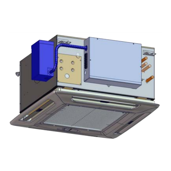
GENERAL PRODUCT INFORMATION Product Description --Single fan models 08, 12, 18 and 20 are designed with fire-retardant plastic or aluminum impellers. • Available in three cabinet sizes with six output capacities --Twin fan models 33 and 36 are designed with fire from 8,000–36,000 Btuh. -
Page 6: Dimensional/Physical Data
DIMENSIONAL/PHYSICAL DATA 3⅝" 3⁵ /₁₆ " Figure 1 - Dimensions: Models 8, 12 2¹¹/₁₆" 3¹¹/₁₆" 3¹¹/₁₆" 5¾" 5¼" 7¹¹/₁₆" FEATURES Optional Discharge Knockouts 5¼ in Diameter (3 Available) Fresh Air Inlet Knockouts 1¼ x 2½ in (2 Available) Condensate Discharge ½... - Page 7 DIMENSIONAL/PHYSICAL DATA 7⅝" 5¹¹/₁₆" Figure 2 - Dimensions: Models 18, 20 3¹/₁₆" " ½ 3" 5¾" " ½ " ½ FEATURES Optional Discharge Knockouts 5¼ in Diameter (3 Available) Fresh Air Inlet Knockouts 1¼ x 2½ in (2 Available) Condensate Discharge ½...
- Page 8 DIMENSIONAL/PHYSICAL DATA 6⅜" Figure 3 - Dimensions: Models 33, 36 5⅝" 4⁵ /₁₆ " 2¼" 5⅜" 7" 1⁵ /₁₆ " 3⅜" FEATURES Optional Discharge Knockouts 5¼ in Diameter (3 Available) Fresh Air Inlet Knockouts 1¼ x 2½ in (2 Available) Condensate Discharge ½...
-
Page 9: Unit Mounting
UNIT MOUNTING Unpacking Figure 4 - Models 08–12 , One Grille & One Filter NOTICE Do not throw template away with packaging. See Figure 8 Page 10. Do not use drain or water connections for lifting. Cassette fascia and main chassis are packaged together. Remove banding straps and lift cardboard lid. - Page 10 UNIT MOUNTING Positioning Ceiling Opening Select cassette installation position. CAUTION Pipe work, electrical connections, control box and Mount unit with lowest moving parts at least 8 feet condensate pump access panels should be readily above floor or grade, to avoid contact with moving accessible.
-
Page 11: Features
FEATURES Mounting Method Figure 9 - Mounting Brackets • In existing construction, remove enough ceiling panels to provide clearance space for mounting unit to ceiling joists. • Before beginning installation, inspect unit location, test strength of ceiling joists to ensure they will support unit weight. -
Page 12: Condensate Piping
CONDENSATE PIPING Figure 12 - Highest Point Of Condensate NOTICE Piping Should Be As Close To Unit As Possible Insulate chilled water and condensate pipes up to chassis to prevent condensation which may damage ceiling and objects located below. Insulate chilled water valves to prevent sweating. Cassette is supplied with 1/2 in (12.7 mm) I.D. -
Page 13: Duct Connections
DUCT CONNECTIONS Attach branch duct and fresh air duct collars to cassette Figure 14 - Knockouts chassis. Install no more than 10 ft (3 m) of branch duct or fresh air duct. Locate knock-out holes. See Figure 14. Number of knockouts vary with unit size. •... -
Page 14: Final Assembly
FINAL ASSEMBLY Assembly Instructions Figure 16 - Mounting Bolts Install four fascia mounting bolts. See Figure 16. a. Locate supplied bolts and washers from kit bag. b. Place washers on bolts. c. Screw mounting bolt with washer into chassis leaving approximately 1 in (25 mm) to hang fascia. Ensure white panel fasteners holding fascia polystyrene are pushed firmly in, fasteners may have loosened in transit. - Page 15 FINAL ASSEMBLY Figure 19 - Connect Vane Motor Plug Into Socket Figure 21 - Secure Fascia To Chassis On Chassis Figure 22 - Adjust Louver Position 30° From Plumb Figure 20 - Connect Infrared Control Cable PN 20009722 REV F, [08/01/2020]...
-
Page 16: Electrical Wiring
ELECTRICAL WIRING General Electrical Requirements Figure 23 - Remove Control Box Cover Electrical wiring must be in accordance with all electrical codes. In absence of such requirements to the National Electrical Code (NEC). Any manufacturer wiring requiring replacement must be replaced with wiring material having temperature rating of at least 105°C. - Page 17 ELECTRICAL WIRING Low-Voltage Electrical Wiring Figure 27 - Wiring Diagram Location Low-voltage interconnect wiring must be 18 AWG. Locate 24 Vac control transformer in air handler. Provides low-voltage control power to both air handler and chilled water valve. Low-voltage interconnect control wiring may vary depending on model selected.
- Page 18 ELECTRICAL WIRING Figure 29 - 08-20 Transformer Figure 31 - 33-36 Transformer Figure 30 - CAW 08-20 Transformer Mounting Figure 32 - CAW 33-36 Transformer Mounting PN 20009722 REV F, [08/01/2020]...
-
Page 19: Thermostat Operation
• Choose 24 Vac, dry contact type thermostat that matches your application. 2. Cooling with Electric Heat or Hot Water Heat • EMI equipment is compatible with most standard Operation bimetal, mercury bulb, digital electronic or power- A. Set thermostat Configuration for cooling/electric stealing thermostats. -
Page 20: Caw Wall Mounted Thermostat Operation
CAW WALL MOUNTED THERMOSTAT OPERATION Figure 33 - CAW Louver Toggle Switch - Sizes WARNING 18/20/30/36 Electrical shock hazard. Turn off power to unit before proceeding. Failure to follow these instructions could result in death or serious injury. NOTICE Unit is equipped with safety switch. Pump is activated when condensate reaches critical level. -
Page 21: Sequence Of Operation - Caw Infrared Control System
SEQUENCE OF OPERATION — CAW INFRARED CONTROL SYSTEM Set Controller Configuration WARNING See Figure 37, Page 26 and Pages 24-34 for operation Electrical shock hazard. Turn off power to of controller and infrared control system handheld unit before proceeding. Failure to follow these remote. - Page 22 SEQUENCE OF OPERATION — CAW INFRARED CONTROL SYSTEM Verify Cooling - With Optional Electric Heat NOTICE This is cooling unit with optional electric or hot water Unit is equipped with safety switch. Pump is heat option in the cassette unit. activated when condensate reaches critical level.
-
Page 23: Caw Infrared Control System - Overview
CAW INFRARED CONTROL SYSTEM - OVERVIEW Figure 35 - Cassette Control Panel WARNING Electrical shock hazard. Verify all power is off before removing control box cover. Failure to follow these instructions could result in death or serious injury. PN 20009722 REV F, [08/01/2020]... - Page 24 CAW INFRARED CONTROL SYSTEM - OVERVIEW Table 3 - CAW Microprocessor Controller — Dip Switch Settings Factory DIP Switch Setting Operation Setting Enables Test Mode. Timers are shortened, quick operational testing. • Anti-short-cycle time reduces from 3 minutes to 45 seconds.
- Page 25 CAW INFRARED CONTROL SYSTEM - OVERVIEW Figure 37 - CAW Infrared Hand Held Control PN 20009722 REV F, [08/01/2020]...
-
Page 26: Caw Infrared Control System - Settings
CAW INFRARED CONTROL SYSTEM - SETTINGS Figure 38 - Configuration Settings CAW PN 20009722 REV F, [08/01/2020]... - Page 27 CAW INFRARED CONTROL SYSTEM - SETTINGS Figure 39 - 7-Day Programming Options For CAW Item Setting Values Overview To access: Press and hold PROGRAM and CLOCK buttons simultaneously 3 seconds; use arrow keys to select position; save selection and exit by repeating button press. Quick copy —...
- Page 28 CAW INFRARED CONTROL SYSTEM - SETTINGS Table 4 - CAW Microprocessor Controller — Dip Switch Settings PN 20009722 REV F, [08/01/2020]...
-
Page 29: Caw Infrared Control System - Operation
CAW INFRARED CONTROL SYSTEM - OPERATION Handheld Remote Operation Power • When power is first applied to control or after power Pressing POWER button momentarily switches unit either outage, there is three (3) minute delay before cooling or on or off. heating begins. - Page 30 CAW INFRARED CONTROL SYSTEM - OPERATION Cooling Mode Dry Mode Dry mode removes humidity from air while maintaining For cooling operation, turn unit on via POWER button. specific setpoint temperature. This is done by cycling Select Cooling mode via MODE button. cooling mode.
- Page 31 CAW INFRARED CONTROL SYSTEM - OPERATION Cooling starts. Unit runs cooling operation as described Quick Copy in Cooling mode. Quick copy is feature of 7-Day Programming mode, used to copy settings of any day to rest of week. If setpoint temperature is above room temperature by auto change over differential amount selected in While in 7-Day Programming, select day to be copied.
- Page 32 CAW INFRARED CONTROL SYSTEM - OPERATION Clean Filter Alarm • When clean filter time has elapsed, Timer/Alarm LED flashes four times to indicate filter needs to be cleaned. Cassette controller indicates when scheduled filter cleaning is required by flashing Timer/Alarm LED. During normal •...
- Page 33 CAW INFRARED CONTROL SYSTEM - OPERATION Table 5 - Microprocessor Controller Fault Indications For Infrared Control System Timer/Alarm LED — number Fault Condition Description of flashes: If room air sensor is disconnected, damaged or malfunctions Timer/ Room Air Sensor Fault Alarm LED will flash one (1) time to signify that fault has occurred.
-
Page 34: Maintenance
MAINTENANCE Figure 40 - Remove Grille WARNING Electrical shock hazard. Before removing access panels, verify all power is disconnected from unit. Failure to follow these instructions could result in death or serious injury. Have service performed by qualified service agency. Clean Filter Clean air filter monthly. -
Page 35: Troubleshooting
TROUBLESHOOTING Wall Mounted Thermostat - CAW Units WARNING Low volt interface requires 18 AWG low-voltage Electrical shock hazard. Before removing access interconnecting wires. panels, verify all power is disconnected from unit. • Terminal “W” is required for units with electric or hot water Failure to follow these instructions could result in heat only. - Page 36 TROUBLESHOOTING CAW Infrared Control System WARNING Cooling only units require 18 AWG minimum low-voltage Electrical shock hazard. Before removing access interconnecting wires. panels, verify all power is disconnected from unit. - Terminal “W” is required for units with electric or hot Failure to follow these instructions could result in water heat only.
-
Page 37: Specifications & System Performance
SPECIFICATIONS & SYSTEM PERFORMANCE Table 6 - Electrical Specifications Fan Motor Elect Heat Total HACR Model Amps Volt BRKR Volts/Hz/ph Amps CAW 08/12 115/60/1 1/10 CAW 08/12 208/230/60/1 0.35 1/10 CAW 08/12 208/230/60/1 0.35 1/10 6.52 60 Hz CAW 18/20 115/60/1 CAW 18/20 208/230/60/1... - Page 38 SPECIFICATIONS & SYSTEM PERFORMANCE CHILLED WATER 2-PIPE CASSETTE COOLING CAPACITIES COOLING CAPACITY CHILLED WATER ENTERING / LEAVING TEMPERATURE ºF (no glycol) "Entering 40/50 °F 45/55 °F Air Flow Dry Bulb Air Total Sensible Flow Pressure Total Sensible Flow Pressure Model Filter Temperature Capacity...
- Page 39 SPECIFICATIONS & SYSTEM PERFORMANCE Table 7 - Shipping Weights Table 8 - Indoor Sound Levels (dBa) Shipping Weight High Model Model lbs (kg) Speed Speed CAW 08/12 70 (31.8) CAW 08/12 CAW 18/20 108 (49.1) CAW 18/20 CAW 33/36 146 (66.4) CAW 33/36 CAW TECHNICAL DATA 08/12...
- Page 40 2201 Dwyer Avenue, Utica, NY 13501 All specifications subject to change without notice. Tel. 800 253 7900 ©2020 ECR International, Inc. www.ecrinternational.com BDR THERMEA GROUP...
Need help?
Do you have a question about the ComfortWave CAW Series and is the answer not in the manual?
Questions and answers