Table of Contents
Advertisement
Advertisement
Table of Contents

Related Manuals for Vishay ESTAmat PFC


Summary of Contents for Vishay ESTAmat PFC
- Page 1 ® ESTAmat Mounting Instructions MV1161 VISHAY ELECTRONIC GMBH - Geschäftsbereich ROEDERSTEIN, ESTA und Hybride Hofmark-Aich-Str. 36 - Phone (49)-871/86-0 - Fax (49)-871/86 25 12 - D-84030 Landshut - Germany www.vishay.com Version 1.2.1 Issue February 2002 Document Number: 13124...
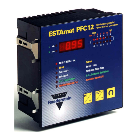
- Page 2 Front Panel Controls Digital display Step LEDs The four-digit display indicates The LEDs indicate the energized actual values, faults, capacitor steps. and the set parameters. yellow lettering: fundamental current I fund (LED1) root-mean-square current I eff Trend LEDs (LED 6) "ind"...
-
Page 3: Table Of Contents
4.4.1.3. Memorizing the C.T. location with AU1..........................13 AU2 ........................14 4.4.2. Semi-automatic initialization AU3 ..........................14 4.4.3. Manual Initialization 4.5. TEST MODE ................................14 5. OPERATING THE ESTAMAT PFC CONTROLLER- MAIN MENU ..............15 5.1. M AUTO – ......................15 AUTOMATIC OPERATING MODE 5.2. M MAN - .........................16... - Page 4 6.3. S – D ....................21 ETTING MENU ESCRIPTION OF THE PARAMETER -1- : Modes of initialization......................21 6.3.1. Parameter -2- : Type of measuring voltage ......................22 6.3.2. Parameter -3- : Connection of measuring voltage....................22 6.3.3. Parameter -4- : Type of switching program.....................22 6.3.4.
-
Page 5: Concise Operating Instructions
21-26 Control terminals for contactors 7-12 (only PFC12) 1.3. Start-up procedure After the supply voltage has been applied to it, the ESTAmat PFC Controller starts a self-test. The following data will be displayed for about 2 seconds: 1.2.1. The type of program e.g.:... - Page 6 2.1 to 2.3 The procedure is repeated three times. Normally, the ESTAmat PFC Controller terminates a successful initialization after approximately 5 minutes, and correctly determines the configuration of the plant, and indicates the actual power factor. If one of the following symbols is on display, the following conditions may be the cause:...
-
Page 7: General
2.2. Automatic identification of C.T. location and of capacitor step output The ESTAmat PFC Controller is capable of determining by itself , during the start-up procedure, the location of the current transformer as well as the output rating of the connected capacitor steps by means of test switchings. -
Page 8: Optimized Switching Performance
In case of, for example, a power factor correction equipment of 25 : 25 : 50 : 50 : 50 kvar, the ESTAmat PFC Controller will immediately switch in a step of 50 kvar instead of gradually switching in steps of 25kvar. This way, the number of switching operations is reduced, which results in an increased life expectancy of both the capacitors and the contactors. -
Page 9: Harmonic Current - Root Mean Square Current
2.10. Measurement of temperature Via an internal temperature sensor the ESTAmat PFC Controller can permanently measure the ambient temperature. Although the sensor is installed within the device, the measuring can be carried out with sufficient precision because of the existing venting slots which allow sufficient air circulation. -
Page 10: Parallel Operation
2.13. Interface The ESTAmat PFC is equipped with a serial interface RS232. By means of a computer, all relevant measuring values and Power Factor Controller data can be requested. Furthermore, all Power Factor Controller's parameters can be modified via a computer. -
Page 11: Connection Of The Estamat Pfc Controller
5. When using capacitors with attached discharge resistors, the necessary time for discharging will be 60 or 180 seconds, which has to be observed for any switching-in of steps. The re-switching blocking delay time of the ESTAmat PFC must be set accordingly via parameter 7. 3.3. Connection instructions for current transformer 1. - Page 12 "undercurrent ≡ 6. The C/k value is set automatically by the ESTAmat PFC Controller in the initialization modes AU1 und AU2. Attention shall be paid, however, that the current of the smallest capacitor step at the transformer secondary is in the range of 0.025 up to a maximum 1.5 A.
-
Page 13: Start-Up Procedure
: NO (not activated) locking of the keyboard If the ESTAmat PFC Controller had been turned to manual operation, the P.F. Controller will automatically go back to manual operation upon return of the supply voltage. Then all capacitor steps which had before been switched in, observing the re-switching blocking delay, will be re-switched in again. -
Page 14: Initialization
Fully automatic initialization AU1 (= standard setting) • The ESTAmat PFC determines the location of the current transformer, the output and number of the capacitor steps, and the switching program. The operator must only set the measuring voltage mode phase to phase L-L or phase to neutral L-0 . (refer to 6.3.1 and 6.3.2). -
Page 15: Part 2 : Determination Of The Current Of Capacitor Steps
C.T. location will be stored permanently. If this is the case, there will appear in the display of the ESTAmat PFC Controller, directly after application of the supply voltage, alternatively AU1 and NO during the period of the re-switching blocking delay. Thereafter, the ESTAmat PFC Controller performs part 2 AU2 (item 4.4.1.2). -
Page 16: Semi-Automatic Initialization Au2
NO : The ESTAmat PFC Controller takes over the stored C.T. location and starts with part 2 = determination of the currents of the capacitor steps. YES : The ESTAmat PFC Controller erases the stored C.T. location and performs part 1 and part 2 of the initialization AU1 4.4.2. -
Page 17: Operating The Estamat Pfc Controller- Main Menu
On the front plate of the ESTAmat PFC Controller six main menu points are laid out. Important control parameters, measuring values, and control characteristics can be enquired for or can be set by means of this main menu. -
Page 18: Mode Man - Manual Operating Mode
5.2. Mode MAN - manual operating mode The manual operating mode can be called upon from any other mode. When the MAN mode is set, the automatic operating mode is ineffective, i.e. no capacitor steps are switched. In order to activate the MAN mode, one must keep pressing the key until the display shows 8888 after about 5 seconds. -
Page 19: Ode Target Cos Φ
The condition of surpassing must be given permanently during the determined switching delay time. The switching delay time can be determined by the ESTAmat PFC Controller as a function of load, or it can be fixed by the operator. -
Page 20: Mode Ic / Σ Switchings, Green Lettering
5.7. Mode harmonic current [%] , orange lettering By means of the FFT-type analysis (Fast-Fourier-Transformation), the ESTAmat PFC Controller can determine harmonic currents of the 3rd, 5th, 7th, 11th, 13th, 17th and 19th harmonic. They are displayed in percentage of the current of the fundamental frequency. These percentage values are displayed up to the 17th harmonic. -
Page 21: Parameter: Setting And Display
6. Parameter: setting and display The parameter can be set in two different ways: at the Controller and • with a PC via the serial interface of the Controller. • 6.1. Parameter in the main menu In the following text, the keys to be activated are marked black.. Example: means that the key IN shall be pressed. -
Page 22: Setting Menu - Modifying The Parameter
The set value is stored via the key Thereafter, the parameter is displayed in alternation with the modified value. 6.2.3. Setting menu – Completing and memorizing the parameter By means of the keys the parameter's number DONE is to be modified until the display indicates . -
Page 23: Parameter -1- : Modes Of Initialization
The ESTAmat PFC Controller determines the current transformer location, the output and number of capacitor steps, and the switching program. Semi-automatic initialization • The ESTAmat PFC Controller determines, after the current transformer location has been set, the output and number of capacitor steps and the switching program. Manual initialization •... -
Page 24: Parameter -2- : Type Of Measuring Voltage
The connection of the measuring voltage needs to be indicated only in case of semi-automatic (= AU2) and manual initialization (= AU3). The table shows all the possible connection combinations to the terminals 12 and 10 of the ESTAmat PFC Controller. Connection of... -
Page 25: Parameter -5- : C/K Value
If RST is selected (see page 20), 1 1 1 1 is reset. 6.3.5. Parameter -5- : C/k value The C/k value is the pick-up value of the ESTAmat PFC Controller. This value is the reactive current responding threshold of the Controller in reactive Ampere. If the reactive current portion of the load exceeds the set C/k value, this will be displayed by one of the two LEDs ("ind"... -
Page 26: Parameter -6- : Number Of Switching Steps
Table with C/k values for 400V: C/k values for 400 V current smallest capacitor step [kvar] trans- former 12.5 16.7 0.72 1.44 50:5 75:5 0.48 0.96 1.20 1.44 100:5 0.36 0.72 0.90 1.08 1.21 1.44 150:5 0.24 0.48 0.60 0.72 0.80 0.96 1.20... -
Page 27: Parameter -8- : Switching-In Delay Time
A number of capacitor steps determined by the operator can be defined as fixed steps. These steps are switched in permanently upon application of the supply voltage to the ESTAmat PFC Controller and after the re-switching blocking delay time has elapsed. The desired number of fixed steps has to be set. -
Page 28: Parameter -12- : Locking Of Keyboard Operation
6.3.12. Parameter -12- : Locking of keyboard operation The parameters of the main menu, e.g.: target power factor, switching time, etc. and the manual operating mode MAN, can be protected against unauthorized adjustment by locking the keyboard. ≡LO[ . Locking is activated, when the display indicates Keyboard operation Display not locked... -
Page 29: Parameter -14- : Switching Out The Capacitor Steps In Case Of Alarm
If RST is selected (see page 20), 2 is reset. 6.3.15. Parameter -15- : Permitted maximum temperature By means of an internal sensor, the ESTAmat PFC Controller can measure the ambient temperature. When the preset maximum temperature is exceeded, the display of the fault alarm ≡T alternates with the display of the actual power factor. -
Page 30: Parameter -16- :Current Factor Rms Current/Fundamental Frequency Current
6.3.17. Parameter -17- : Maximum permissible values for the harmonic current For the harmonic portions of the 3rd; 5th; 7th; 11th; 13th; 17th and 19th harmonic, 10 maximum value profiles in percentage can be set. When at least one harmonic wave exceeds its set maximum value for a period of 5 minutes, the fault alarm ≡HAR is triggered. -
Page 31: Fault Elimination
7. Fault elimination 7.1 Operation and fault display Symbol Type Description Reaction of ESTAmat PFC Fault elimination - measuring current too low, C.T. may be too large. capacitor steps will be - connection to C.T. may have broken. failure of... - Page 32 Symbol Type Description Reaction of ESTAmat PFC Fault elimination fault during AUI could not be completed - Controller cannot determine the C.T. location easily owing initialization ≡AUI five trial runs are made to the quick load changes without faults mode AUI...
- Page 33 Symbol Type Description Reaction of ESTAmat PFC Fault elimination after the given alarm and with a 5 minutes delay, steps Switching alarm ≡IEF or ≡T is given and will continue being switched out of ≡COS out. - No fault function!, refer to ≡IEF and ≡T...
-
Page 34: General Faults
7.2 General faults Fault display Cause - supply voltage is missing. Display remains blank. - equipment fuse is defective. Possibly the applied supply voltage is too high. Controller does not react to changes; display shows actual cos ϕ - Controller has been changed to 'MAN', press key to revert to automatic operation. -
Page 35: Technical Data
8. Technical Data 8.1. Measuring circuit Voltage range 58 V to 690 V, stepless Current range 25 mA to 5 A Frequency 50 Hz (60 Hz upon request) Input filter each measuring circuit is provided with a band-pass filter Voltage connection phase to phase or phase to neutral Current power input 1 VA maximum... -
Page 36: Mechanical Details
8.5. Mechanical details Front panel 142 x 142 mm Panel cut-out 138 x 138 mm Depth approximately 70 mm Weight 0.65 kg maximum (PFC12) Design to EN 50178, protective class II, and EN 61010-1, EN50081-2, EN61000-6-2 Type of protection IP 40 with multipoint connector mounted (IP 55 upon request;... -
Page 37: Flowdiagram Of Parameters In The Setting Menu
9. Flow Diagram: Parameters in the setting menu -1- Modes of initialization Type of measuring voltage L-0 or L-L -3- Connection of measuring voltage (Setting value as a function of the C.T. phase) Connection of Connection of measuring voltage measuring voltage L1 –... - Page 38 -12- Locking of keyboard operation (≡LO[ ) Keyboard operation Display not locked locked -13- Functioning of the alarm relay Alarm signals ≡ ≡ ≡ ≡ ≡ ≡ ≡ Display -14- Switching out the capacitor steps in case of alarm 1 = the capacitor steps will be switched out immediately without time delay. 2 = the capacitor steps will be switched out after a time delay which can be modified (parameter -19- ) 3 = steps will continue being switched out until the fault alarm has disappeared.
Need help?
Do you have a question about the ESTAmat PFC and is the answer not in the manual?
Questions and answers