
Related Manuals for Rowan Elettronica 380S


Summary of Contents for Rowan Elettronica 380S
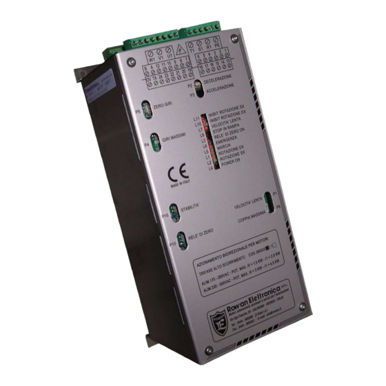
- Page 1 INSTRUCTION MANUAL Cod.380S.B BIDIRECTIONAL DRIVE FOR ROWAN S SERIES HIGH SLIP THREE PHASE MOTORS CONFORMITY Motori, azionamenti, accessori e servizi per l'automazione REV. 2 - Data 18/03/11 Data Controllato/Approvato...
-
Page 2: Table Of Contents
- Regarding the data and characteristics mentioned in the manual, a maximum tolerance of 10% has been allowed, if not otherwise indicated. - The product guaranty is considered ex-works and is valid 6 months from the date of leaving ROWAN ELETTRONICA s.r.l. -
Page 3: Technical Characteristics - Dimensions
WARNING: Conformity to these regulations is subject to the connection of filtering devices supplied separately and to the careful observance, by the installer, of the instructions on page 16. in mm) OVERALL DIMENSIONS ( ROWAN ELETTRONICA SRL page 3 out of 24... -
Page 4: Operating Principal
3 times the nominal couple . The ROWAN 380S+ high speed motor system is particularly indicated therefore for fast movements (e.g.: axle control) also with large inertial loads, not needing any external device such as the braking resistance used for frequency control of normal asynchronous motors or for DC motor drivers. -
Page 5: Connection Diagrams
- If the board to be substituted is set differently from factory standard, bear in mind that the dip-switches and the trimmer with the same initials on the 380S have kept the same functions and therefore it is sufficient to set them in the same way as the 280S.B/0 and 280R. -
Page 6: Led Signal Description
Couple control setting (see page 10). S14-S15-S16-S17-S18 Logic command input contact NO/NC settings. Speed set by potentiometer or ±10VDC differential signal selection (see page 9). Power supply frequency selection 50Hz / 60Hz (see page 17). ROWAN ELETTRONICA SRL page 6 out of 24... -
Page 7: Command And Power Connectors Description
NO contact connected internally to ground. di emergenza External potentiometer ACC./DEC. ramps regulation connectors: External potentiometer acceleration/deceleration regulation ramps common connector. ACCELERATION RAMP (470 kohm) external potentiometer connection connector. DECELERATION RAMP (470 kohm) external potentiometer connection connector. ROWAN ELETTRONICA SRL page 7 out of 24... -
Page 8: 380S Board Setting And Command Instructions: Board Presetting For The Number Of Motor Poles
- with S3 closed and P2 at maximum external ramp regulation from 20sec (0k ) to 40 sec (470k - with P2 at minimum external acceleration ramp regulation field as internal regulation ramps. ROWAN ELETTRONICA SRL page 8 out of 24... -
Page 9: Dc Signal Or Potentiometer Speed Regulation
- Differential input pilotable by interface board, positioning instruments, PLC or computer with guaranteed galvanic isolation from the high tension and immune from common interference. - Connection must be made with screened cable. ROWAN ELETTRONICA SRL page 9 out of 24... -
Page 10: Rowan High Speed Motor Couple Regulation
P8 (regulating clockwise) to re-enter in the current regulation field. WARNING: bear in mind that, when regulating couple, in blocked rotor operation, Rowan motor maximum current in continuous operation must be at least 20% less than the nominal current. ROWAN ELETTRONICA SRL page 10 out of 24... -
Page 11: Command Inputs Description
- The opening / closing of dip-switch S14 causes, in any case, the activation / deactivation and therefore gives the possibility to adapt the input to any type of both NO and NC command. ROWAN ELETTRONICA SRL page 11 out of 24... - Page 12 - The opening / closing of dip-switch S17 causes, in any case, the activation / deactivation and therefore gives the possibility to adapt the input to any type of both NO and NC command. SLOW SPEED SLOW SPEED ROWAN ELETTRONICA SRL page 12 out of 24...
-
Page 13: Output Description
- If PNP logic, in an emergency situation when led L6 lights and the PLC input passes from 20VDC to 0VDC. EXTERNAL INPUT /OUTPUT NPN/PNP (PLC) LOGIC CONNECTION DIAGRAM INPUTS OUTPUTS INPUTS OUTPUTS Fig. 1 ROWAN ELETTRONICA SRL page 13 out of 24... -
Page 14: Rowan S Series Motor Connection Instructions
ELECTRICAL CHARACTERISTICS TABLE OF THE MOTORS APPLICABLE TO THE 380S BOARD For motor overload / overheating protection the use of the thermic sensor contact located on the motor windings and available at the service connector is quite sufficient. -
Page 15: Motor Service Connector Connection
It is necessary to bear in mind that the flywheel diode has a maximum filtering efficiency, but it delays spring brake insertion. Note: for a better use of the brake, Rowan Elettronica suggests the following connection to the C321S device: BRAKE... -
Page 16: Installation Instructions: Mechanical Installation
ELECTRICAL PROTECTION The Cod.380S board is provided with a protection device which intervenes when the motor is out of tachometrical control, such as in the case of overload, power-line and motor phase loss, tachometrical loss and tachometrical polarity inversion; The emergency intervention removes motor rotation enable and excites the emergency externally connected relay;... -
Page 17: Start Up
Connect in a star or triangle way, according to the line and motor plate data; connect the motor to earth. The tachometrical dynamo signal, which is to be connected to the 380S board connectors 21 - 22 , is obtained from the motor service connectors 1 - 2. -
Page 18: Troubleshooting
DEFAULT SETTINGS AND STANDARD SETTINGS The cod.380S board leaves Rowan tested with the following settings: - Trimmer positions as shown come shown on the component lay out diagram page 21. -
Page 19: Forward/Backward Movement With Pre-Stop Slowing For Precise Stopping With The Brake Command
CONNECTION DIAGRAM FCSX = limit stop SX LSX = limit slowing SX FCDX = limit stop DX LDX = limit slowing DX ROWAN ELETTRONICA SRL page 19 out of 24... -
Page 20: Block Diagrams
BLOCK DIAGRAM ROWAN ELETTRONICA SRL page 20 out of 24... -
Page 21: Components Layout
COMPONENTS LAYOUT ROWAN ELETTRONICA SRL page 21 out of 24... -
Page 22: Maintenance Instructions For The S Series Rowan Motors (High Slip Type)
A good brake operation can be guaranteed only if original components, supplied by our firm, are used. For more detailed information contact the technical department at Rowan Elettronica. N.B. When the air gap reaches a value equal to 0,7 mm it is necessary to bring such value to 0,2 mm Counter-indications The correct brake operation may only be guaranteed when working at room temperature. -
Page 23: Translation Of The Text In The Drawings
DISGIUNTORE TERMICO: THERMIC SWITCH DISPOSITIVO CONTROLLO TACHIMETRICO: TACHOMETRICAL CONTROL DEVICE DX.: CK. EMERGENZA: EMERGENCY FRENO A MOLLE: SPRING BRAKE FRENO DIRETTO: DIRECT BRAKE FUSIBILI RAPIDI TIPO GL CONSIGLIATI: RAPID GL TYPE FUSES RECOMMENDED ROWAN ELETTRONICA SRL page 23 out of 24... - Page 24 GIRI MASSIMI: MAXIMUM SPEED GRUPPO INGRESSI LOGICI: LOGIC INPUT GROUP GRUPPO SINCRONISMI E GENERATORI DI IMPULSO: SYNCRONISING GROUP AND IMPULSE GENERETOR INDUTTANZA TRIFASE: THREE PHASE INDUCTANCE INGRESSI: INPUT INIBIT DX: RIGHT INHIBITION. INIBIT SX: LEFT INHIBITION . INIBIZIONE ROTAZIONE DX: INHIBIT CLOCKWISE ROTATION INIBIZIONE ROTAZIONE SX: INHIBIT ANTICLOCKWISE ROTATION INPUT 0V LIMITAZIONE MASSIMA: MAXIMUM INPUT LIMIT 0VDC INPUT 10V LIMITAZIONE MINIMA: MINIMUM INPUT LIMIT 10VDC...
Need help?
Do you have a question about the 380S and is the answer not in the manual?
Questions and answers