Table of Contents
Advertisement
Advertisement
Table of Contents

Related Manuals for Titan TR7

Summary of Contents for Titan TR7
- Page 1 GNSS RTK System User Manual...
- Page 2 Manual Revision Revision Date Revision Number Description May. 2019 A1 version...
-
Page 3: Preface
TR7 GNSS System User Manual Preface Introduction Welcome to the TITAN TR7 receiver. This introduction describes how to use this product. Tips for safe use Note: The contents here are special operations and need your special attention. Please read them carefully. -
Page 4: Table Of Contents
TR7 GNSS System User Manual Contents Preface ..............................3 Overview ..............................6 Features ..............................7 Product Introduction ........................8 2.1 Hardware structure ........................9 2.1.1 Upper cover ..........................9 2.1.2 Bottom cover ......................... 10 2.1.3 Control panel ......................... 12 2.2 Button & LED ..........................12 2.2.1 Button ............................12 2.2.2 LED ............................ - Page 5 TR7 GNSS System User Manual 2.4 Static mode ..........................25 2.4.1 Static settings ........................25 2.4.2 Static mode steps ........................ 25 2.4.3 Static data download ......................26 2.5 Dynamic RTK surveying ...................... 27 2.5.1 Base setting ..........................27 2.5.2 Base station parameters setting ..................27 2.5.3 Rover setting .........................
-
Page 6: Overview
TR7 GNSS System User Manual Chapter 1 Overview This Section Describes - Features www.titanposition.com... -
Page 7: Features
10. Double format storage of static data (*.GNS / RINEX). 11. The new generation controller THC30 with ergonomic design supports 4G, OTG, quick charge by dedicated charger and so on. 12. With the new TR7 software with new UI, multiple base maps and so on. www.titanposition.com... -
Page 8: Product Introduction
TR7 GNSS System User Manual Chapter 2 Product Introduction This Section Describes - Hardware structure - Button & LED - Touch display - Web management system - Static measurement - Real Time Kinematic (RTK) surveying - Tilt survey 2.0 - Firmware upgrade... -
Page 9: Hardware Structure
TR7 GNSS System User Manual 2.1 Hardware structure The product appearance is divided into three parts, including the upper cover, bottom cover and control panel. Upper cover Lower cover Control Panel Figure 2-1-1 Front 2.1.1 Upper cover Anti-wear buffer Figure 2-1-2 Upper cover - Anti-wear buffer: Wear prevention points can enable the host to avoid scratches. -
Page 10: Bottom Cover
TR7 GNSS System User Manual 2.1.2 Bottom cover The bottom cover includes a five-pin socket, a power light & button, a Mini USB socket, a speaker, a battery compartment, a connection screw, etc. Figure 2-1-3 Bottom cover Figure 2-1-4 Bottom cover... - Page 11 TR7 GNSS System User Manual Figure 2-5 Nano SIM slot 1- Five-pin interface 2-Network/Radio antenna interface 3-Rubber buffer 4-USB socket and plug 5-Power light & button 6-Battery slot cover 7-Nano SIM slot - USB socket: connect the host with external devices, to upgrade firmware and download static data. It supports OTG.
-
Page 12: Control Panel
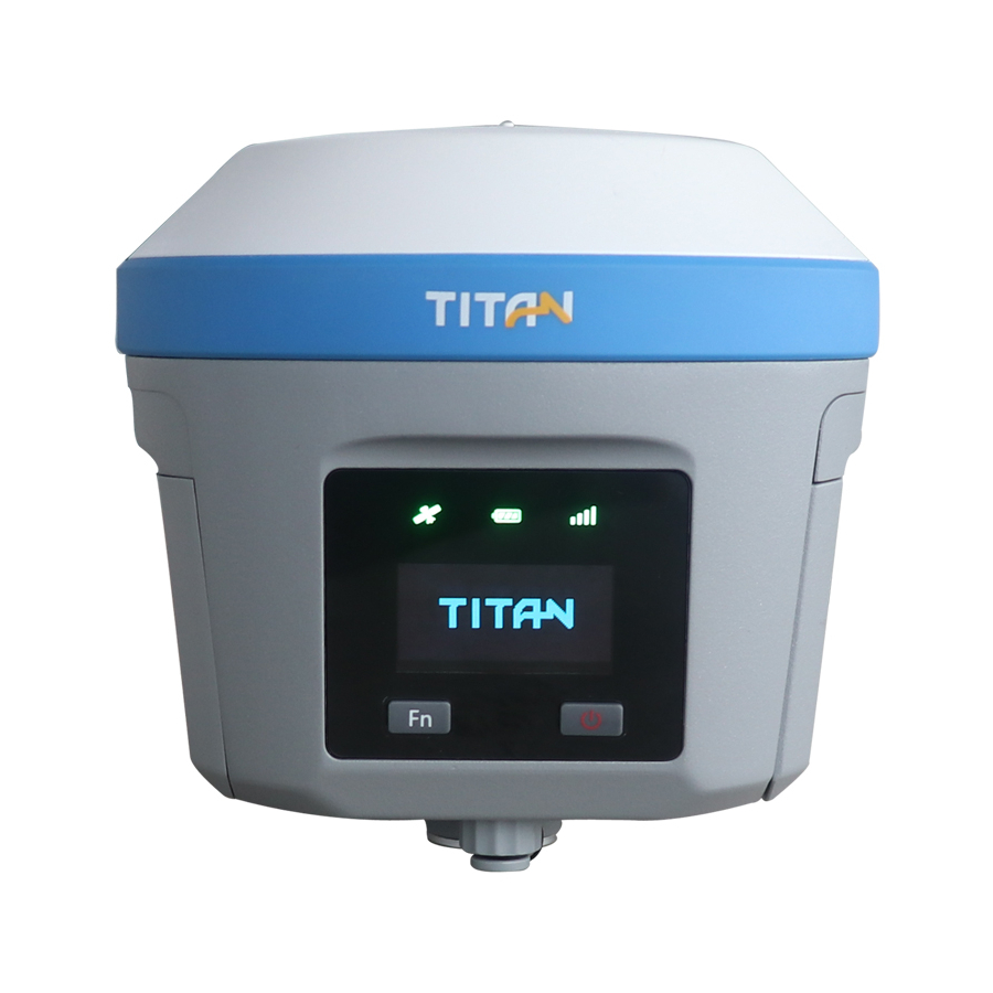
2.1.3 Control panel The control panel includes Fn button, power button and LED screen. The 3 status LEDs correspond to satellite LED, power LED and data LED. Only 2 buttons totally deal the basic functions of the TR7. 3-Power LED... -
Page 13: Led
TR7 GNSS System User Manual Table 2.2.2 Power button function description Function Description Power-on Press the button for 1 second. Power-off Press the button for at least 3 seconds. Double click the power button to open or close the OLED OLED screen switch display. -
Page 14: Oled Screen Display Function
TR7 GNSS System User Manual 2.2.3 OLED screen display function The host has a built-in OLED display. The OLED screen displays the state by double-clicking the power button to turn off the OLED screen display. Double-click the power button in the OLED screen to turn off the display. -
Page 15: Sleep Interface
TR7 GNSS System User Manual Display current receiver operating External Base mode, satellite information, solution status, PDOP Display current receiver operating UHF Rover mode, satellite information, solution status, PDOP, radio protocol Display current receiver operating GSM Rover mode, satellite information, solution... -
Page 16: Setting Interface
TR7 GNSS System User Manual 2.2.6 Setting interface Table 2.5 Instructions for setting interface Function Button operation Contents Close/open Double-click OLED screen Power button Click the Fn button and the selection box will automatically jump to the next option. Single-click... - Page 17 TR7 GNSS System User Manual Click the FN button to select Static, and then click the power button to confirm: static acquisition is not enabled, the collection interval setting interface is displayed, and 1S/5S/10S/15S/30S can be set. Static Click the Fn button to select acquisition is enabled, and “Stop recording?”...
-
Page 18: Web Management System
Other functions: Static, reset function is available. 2.3 Web Management System TR7 has a built-in WEB management system that allows real-time monitoring and free configuration of the host. The name of the receiver WiFi hotspot is the instrument Serial Number. Connect the hotspot via the controller WiFi (no password required), and enter the IP address 192.168.20.1 in the controller browser to log in. - Page 19 TR7 GNSS System User Manual Figure 2-9 Figure 2-10 Figure 2-11 Figure 2-12 www.titanposition.com...
- Page 20 TR7 GNSS System User Manual main menu Submenu Function Device model, version information, registration information, Device information etc. Device positioning coordinates, device search star, solution Position information status, etc. Information Base information Base station coordinates and base station level Skyplot...
-
Page 21: Information View
TR7 GNSS System User Manual 2.3.2 Information View - Equipment information Displays the main information of the current device: device model, serial number, firmware version, motherboard information, expiration date, power, working mode, and configuration parameters. - Location information Displays the current device location information, satellite status, solution status, differential age and PDOP, real time. -
Page 22: Working Mode
TR7 GNSS System User Manual 2.3.3 Working mode - Rover Set the data link of the mobile station and the configuration parameters corresponding to the data link. The mobile station data link mode includes:Internal UHF, internal GSM and external radio. -
Page 23: Firmware Management
TR7 GNSS System User Manual 2.3.5 Firmware management - Update Display the specific device version information, click Select, select corresponding upgrade package and click Upgrade, the host will automatically detect the upgrade package and upgrade. Restore the system Restore the system to its state after the most recent upgrade of the firmware. - Page 24 TR7 GNSS System User Manual - - Radio setting HIT Radio Optional radio modulation protocol (HI-TARGET, TRIMTALK450S, SOUTH, CHC) User-defined settings of 100 to 115 radio channels. - Registration Display the registration validity period of the host; Select the registration type, input the registration code and then you can register device online.
-
Page 25: Static Mode
2.4 Static mode 2.4.1 Static settings TR7 receivers can be used for static survey; There are three ways to set up the device to work in the static mode: - OLED – Static settings – to set up static mode. -
Page 26: Static Data Download
TR7 GNSS System User Manual 2.4.3 Static data download 1. Download the static data by USB cable Connect the receiver with computer by the Mini USB data cable, and copy the static data to computer. The static measurement data is in the gnss folder of the static drive. -
Page 27: Dynamic Rtk Surveying
TR7 GNSS System User Manual 2.5 Dynamic RTK surveying 2.5.1 Base setting The dynamic RTK surveying can be in the radio mode (internal radio, external radio) and network mode depending on how the differential signal is transmitted. - Erection The receiver is located at a stable known or unknown point. In order for the receiver to be able to search for... -
Page 28: Firmware Upgrade
Figure 2-41 Figure 2-42 2.6 Firmware upgrade You can upgrade TR7 firmware via USB cable, Web UI, OTG, or remote online, etc. 2.6.1 Upgrade by USB cable Steps to upgrading the firmware by USB cable: 1. Turn on the receiver, connect the random receiver and computer with the cable attached. It will show the update drive after clicking the computer. -
Page 29: Upgrade By Otg
TR7 GNSS System User Manual 3. There will be different prompt voice of upgrade successes or failures. If it fails, please re-upgrade it or contact our technical team. Figure 2-43 2.6.2 Upgrade by OTG Insert OTG when the USB drive connected with OTG is stored with a firmware that matches the instrument, and the prompt voice is broadcast new firmware found. -
Page 30: Tilt Survey 2.0
TR7 GNSS System User Manual 2.7 Tilt Survey 2.0 After connecting the receiver with the TSI software, active the tilt survey function Slope Method 2.0 in Data interface of the Surveying configure tab, then surveyor can carry out the tilt survey. -
Page 31: Technical Specifications
TR7 GNSS System User Manual Chapter 3 Technical Specifications This Section Describes - Technical Specifications www.titanposition.com... -
Page 32: Technical Specifications
TR7 GNSS System User Manual 3.1Technical Specifications Below are the technical specifications of the product: Table 3-1 Specifications of TR7 Processor Cotex-A5 Core Processor Operating system Linux 3.2.0 System Start-up time 3 Seconds configuration RAM: 128MB; Data storage ROM: 16GB internal storage, support OTG. - Page 33 TR7 GNSS System User Manual HI-TARGET, TRIMTALK450S, TRIMMARK III,TRANSEOT, Protocols SATEL-3AS, etc.. 4FSK 、 GMSK Modulation 403-473MHz Frequency range 25KHz Radio parameter Channel spacing -116 dBm Receiving sensitivity 100(Default)+16(Custom) Number of channels 4W/2W/1W(Optional) Transmit power 2.4GHz, HSP/HFP/OPP/PBAP, V2.1(Transmission distance ≥ 15...
-
Page 34: Accessories
TR7 GNSS System User Manual Chapter 4 Accessories This Section Describes - SIM card installation - Data cable - Antenna - Benchmark - Battery & Charger www.titanposition.com... -
Page 35: Sim Card Installation
Figure 4-1 Figure 4-2 4.2 Data cable Mini USB data cable: Connect the TR7 host and the computer to upgrade the firmware and download static data. Five-pin data cable (DG-3): to connect the host and external radio to transmit differential data. -
Page 36: Benchmark
TR7 GNSS System User Manual Figure 4-6 4G antenna Figure 4-7 4G Radio antenna 4.4 Benchmark The benchmark is used to measure the height of the instrument. Figure 4-8 Benchmark 4.5 Battery & charger - Installation 1, Lightly press the metal button on the battery cover and push it down. - Page 37 TR7 GNSS System User Manual 3, Align the side of the battery with the metal piece down on the battery compartment and push it in gently (the battery installation is completed). Figure 4-11 Steps of unload the battery - Remove Gently press the battery lever, the battery will automatically pop up, pour out the battery, and complete the battery unloading.
- Page 38 TR7 GNSS System User Manual There are 4 indicator lights in all: Table4.1 indicator lights description Operation Battery power LED indicator 0-25% LED 1 flashes, the flashing frequency is 1Hz. LED 1 is in long-term lighting; 25%-50% LED 2 flashes, the flashing frequency is 1Hz.
- Page 39 TR7 GNSS System User Manual - high or low extreme temperatures that a battery can be subjected to during use, storage or transportation; - low air pressure at high altitude. - replacement of a battery with an incorrect type that can defeat a safeguard (for example, in the case of some lithium battery types);...
- Page 40 TR7 GNSS System User Manual www.titanposition.com 19O112...
Need help?
Do you have a question about the TR7 and is the answer not in the manual?
Questions and answers