Table of Contents
Advertisement
Quick Links
Advertisement
Table of Contents
Troubleshooting

Subscribe to Our Youtube Channel
Related Manuals for RLE SeaHawk LDRA6


Summary of Contents for RLE SeaHawk LDRA6
- Page 1 LDRA6 User Guide Version 2.6...
- Page 2 Copyright and Trademark Notices © Raymond & Lae Engineering, Inc. 2011. All rights reserved. RLE® is a registered trademark and Seahawk™, Falcon™, and Raptor™ are trademarks of Raymond & Lae Engineering, Inc. The products sold by Raymond & Lae Engineering, Inc. are subject to the limited warranty, limited liability, and other terms and conditions of sale set forth at http://www.rletech.com/.
- Page 3 Product Serial Number Product Manufacture Date The LDRA6 is not a field-serviceable item and must be sent back to RLE Technologies for mechanical repair. Power must be disconnected (unplugged) from the LDRA6 any time the unit is mechanically serviced. Physically unplug power from the unit any time you are making wiring connections to or from the LDRA6.
- Page 4 Manufactured parts for a period of twenty four (24) months after shipment. These warranties shall remain in effect for RLE distributor supplied parts for a period defined by the original manufacturer’s warranty after shipment. All parts replaced or repaired in the warranty period shall carry the unexpired portion of the original warranty.
-
Page 5: Table Of Contents
Contents Product Overview ........... 11 Description . - Page 6 mbp – View / Change Modbus Parity ..........30 mr –...
- Page 7 Figures Product Overview ........... 11 Figure 1.1 LDRA6 Front Panel Indicators .
- Page 8 LDRA6 User Guide 800.518.1519...
- Page 9 Tables Product Overview ..........11 Connections and Settings .
- Page 10 LDRA6 User Guide 800.518.1519...
-
Page 11: Product Overview
H A P T E R RODUCT VERVIEW HAPTER 1.1. Description The LDRA6 is a complete monitoring system that detects and reports the presence of water and other conductive liquids, as well as monitors dry contact alarm points. The LDRA6 couples SeaHawk Water Leak Detection Cable (SC) with an advanced control head to monitor six individual zones. -
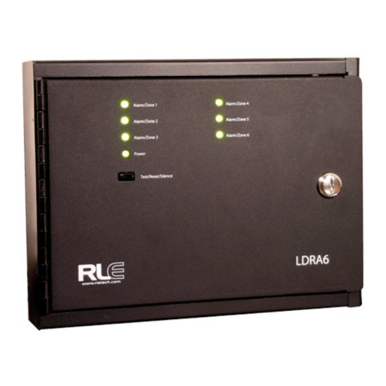
Page 12: Ldra6 Front Panel Indicators
Product Overview 1.2. LDRA6 Front Panel Indicators 1.2.1 Zone LEDs One tri-color LED for each zone. Default Leak Detection Cable Setting: On solid and green for normal cable conditions. Flashes quickly and turns red if a leak is detected in the zone. Flashes quickly and turns yellow if a cable fault is detected in the zone. -
Page 13: Connections And Settings
H A P T E R ONNECTIONS AND ETTINGS HAPTER 2.1. LDRA6 Board The LDRA6's zone connectors, labeled TB2 and TB3, are found at the bottom of the right side of the board. The switches on the board labeled SW1 control some relay and alarm functionality. -
Page 14: Tb1 -- Input Power
2.1.1 TB1 –- Input Power The LDRA6 requires an isolated power supply, RLE part PSWA-DC-24 (24VDC isolated supply). This power supply is not included with the LDRA6. It is available from RLE and sold separately. Power can be wired to the LDRA6 through TB1. If you are using TB1 you may need to cut the barrel connector off of your power supply and strip the ends of the wires so they can be inserted into the terminal blocks. - Page 15 Connections and Settings Position Leak Detection Cable Dry Contact Wire TB3-1 Zone 1 White Zone 1 Input-1 TB3-2 Zone 1 Black Zone 1 Input-2 TB3-3 Zone 1 Green TB3-4 Zone 1 Red TB3-5 Zone 2 White Zone 2 Input-1 TB3-6 Zone 2 Black Zone 2 Input-2 TB3-7...
-
Page 16: Tb5, Tb4 - Zone Alarm Relays
Connections and Settings 2.1.4 TB5, TB4 – Zone Alarm Relays These are the Zone Alarm Relay output terminal blocks (Form C). A status LED is located above each relay, which will indicate the state of the relay (on/off). These relays can be configured as supervised or unsupervised, latched or unlatched (unsupervised and unlatched by factory default). -
Page 17: Tb6 - Summary Relay
Connections and Settings 2.1.5 TB6 – Summary Relay This is the Summary Relay output terminal block (Form C). A status LED is located to the right of the relay, which will indicate the state of the relay (on/off). This relay can be configured as supervised or unsupervised, latched or unlatched. -
Page 18: Sw1- Relay And Alarm Function
Connections and Settings 2.2. SW1– Relay and Alarm Function 2.2.1 SW1, Position 1: Summary Relay Supervised/ Unsupervised The SW1, position 1 configures the Summary Alarm relay as supervised or unsupervised. If a relay is supervised, the relay picks until power goes off or until an alarm is detected. The alarm then releases to announce a change in state. -
Page 19: Sw1, Position 5: Leak Alarm Delay
Connections and Settings 2.2.5 SW1, Position 5: Leak Alarm Delay The SW1, position 5 switch designates the unit’s leak delay time. Setting this switch to “off” delays the default leak alarm by 15 seconds. Setting this switch to 'on' designates the leak alarm delay to use the value specified through the unit's craft port. -
Page 20: Sw4 Through Sw9
Connections and Settings 2.4. SW4 through SW9 SW4 through SW9 configure each zone as a Leak Detection Cable input or a Dry Contact input. If configured as a Leak Detection Cable input, the zone requires a 4-wire leak detection cable (SC) to monitor. If configured as a Dry Contact input, the zone requires a 2-wire dry contact device to monitor. -
Page 21: R1 - Leak Detection Cable Sensitivity Setting
Connections and Settings 2.5. R1 – Leak Detection Cable Sensitivity Setting This potentiometer allows users to manually adjust the sensitivity setting for all six zones. Turn the dial clockwise to make the zone less sensitive. This means a leak will be reported in that zone when a large amount of water is present. - Page 22 Connections and Settings LDRA6 User Guide 800.518.1519...
-
Page 23: Installation
Connect the Water Leak Detection Cable A leader cable kit (RLE part LC-KIT) is required per zone to connect the LDRA6 to SeaHawk Leak Detection Cable (SC). A leader cable is included in each LC-KIT; one end of this leader cable connects into the LDRA6. -
Page 24: Secure The Cable To The Floor
Installation Figure 3.1 Water Leak Detection Sensing Cable Connection Figure 3.2 SD-Z1 Spot Detector Connection The SD-Z1 connects to the LDRA6 in a manner similar to the LC-Kit. One SD-Z1 is designed to connect to each Zone input on the LDRA6. If multiple points are need to be monitored on one zone input, it is recommended to use the SD-Z style spot detector which connects together in series for multiple detection points. -
Page 25: Recommended Cable Installation
Installation 3.2.2 Recommended Cable Installation Figure 3.3 Cable Installation Methods rletech.com LDRA6 User Guide... -
Page 26: Apply Power To The Unit
Installation 3.3. Apply Power to the Unit Once cable for all the desired leak detection zones has been connected to the unit, power may be applied. The LDRA6 operates on 24VDC power supplied by a wall adapter or a direct line. A power supply should be run to the location of the unit. -
Page 27: Eia-232 Interface
H A P T E R EIA-232 I NTERFACE HAPTER 4.1. Boot-Up Make sure the EIA-232 port is connected to a PC or terminal with a straight through cable. When the LDRA6 is powered up, the boot ROM and flash program code are verified. The Screen displayed below should appear on the terminal or terminal emulation software. -
Page 28: Help Menu
EIA-232 Interface 4.2. Help Menu Once the system reaches this point, type? and press Enter to display the Help Menu. The Help Menu lists the function commands for the LDRA6. Figure 4.2 EIA-232 Interface - Help Menu 4.3. Function Commands 4.3.1 c –... -
Page 29: Ld - Leak Delay Setting
EIA-232 Interface 4.3.2 ld – Leak Delay Setting ld displays the current leak alarm delay in seconds. This is the number of seconds the leak alarm must be detected before annunciated. The leak alarm delay can range from 0 to 999 seconds. -
Page 30: E - View Eeprom Data
EIA-232 Interface 4.3.4 e – View Eeprom Data This function is a reserved command used for advanced diagnostic purposes only. 4.3.5 er – Erase Eeprom Data – Restores Factory Defaults er will erase all RS232 configured settings and restore them all to factory default values. 4.3.6 mbb –... -
Page 31: M - View Modbus Port Settings And Statistics
EIA-232 Interface 4.3.9 m – View Modbus Port Settings and Statistics m will display the current EIA-485 Modbus port settings and logged statistics. Initial values appear as: Figure 4.8 EIA-232 Interface - Modbus Port Setting and Statistics 4.3.10 t – Toggle Modbus Trace On/Off t will toggle Modbus tracing with packet viewing from the EIA-485 port over the EIA-232 port. -
Page 32: Zr - Zone Relay Mode
EIA-232 Interface 4.3.13 zr – zone relay mode zr will display the current configuration of the zone relays. You can select the zone relays to either change state on leak/fault (summary) or just a leak condition. Enter, zr <space> summary for notification on a leak/fault condition. Enter, zr <space> leak for notification on a leak condition. -
Page 33: A Modbus Communications
P P E N D I X ODBUS OMMUNICATIONS HAPTER This document describes the Modbus communications protocol as supported by the LDRA6. It includes details and information on how to configure the LDRA6 for communications via Modbus network. A.1. Modbus Implementation of the LDRA6 The LDRA6 is capable of communicating via the half-duplex EIA-485 serial communication standard. -
Page 34: Function Field
Modbus Communications A.1.1.2 Function Field The function field tells the LDRA6 which function to perform. Function codes are designed to invoke a specific action by the LDRA6. A.1.1.3 Data Field The data field varies in length depending on whether the message is a request or a response to a packet. -
Page 35: Read Input Registers
Modbus Communications Register Name Description Units Range 40005 Leak Threshold Zone 5 Trip current for leak 0-65535 Amps alarm 40006 Leak Threshold Zone 6 Trip current for leak Amps 0-65535 alarm 40007 Reserved 40008 Reserved 40009 Reserved 40010 Silence Alarm Set to 1 to silence 1 = Silence 0-65535 audible alarm... -
Page 36: Table A.4 Input Registers
Modbus Communications Register Name Description Units Range 30001 Status Bit Level Status (see None 0-65535 Table 5) 30002 Leak Current Zone 1 Leakage current on Amps 0-65535 cable 30003 Leak Current Zone 2 Leakage current on Amps 0-65535 cable 30004 Leak Current Zone 3 Leakage current on 0-65535... -
Page 37: Present Single Register
Modbus Communications Read Registers Response Packet Table A.5 Status Flags (Register 30001) (continued) Read Registers Response Packet 0 = Zone 1 Configured for Leak Detection / 1 = Zone 1 Configured for Dry Contact 0 = Zone 2 Configured for Leak Detection / 1 = Zone 2 Configured for Dry Contact 0 = Zone 3 Configured for Leak Detection / 1 = Zone 3 Configured for Dry Contact 0 = Zone 4 Configured for Leak Detection / 1 = Zone 4 Configured for Dry Contact 0 = Zone 5 Configured for Leak Detection / 1 = Zone 5 Configured for Dry Contact... -
Page 38: Present Multiple Registers
Modbus Communications A.2.4 Present Multiple Registers To set multiple LDRA6 parameter values, the master must send a Preset Multiple Registers request packet. The Preset Multiple Register request packet specifies a starting register, the number of registers, a byte count and the data to write to the registers. The register is numbered from zero (40001 = zero, 40002 = one, etc.). -
Page 39: Rtu Framing
Modbus Communications For address's 128-191, set SW1-7 to off, #8 to on, then subtract 128 from the address and use the table. For address's 192-254, set SW1-7 & 8 to on, then subtract 192 from the address and use the table. -
Page 40: Modbus Mirroring
Modbus Communications A.4. Modbus Mirroring To use the EIA-485 Modbus mirroring feature set the address on the master LDRA6 to address 255 and then set the address on the slave LDRA6 to 1. The Master unit will then repeat (mirror) any zone alarms that come into the Slave Unit. When using this feature none of the local Alarm/Zone inputs will work on the Master unit, The Master unit is only a repeater for the single slave unit being used. -
Page 41: Troubleshooting
If power is not present at TB1 pins 1 and 2, check DC voltage at DC supply source distribution panel. If voltage (power) is present at TB1, please contact RLE Technologies. Table B.1 Troubleshooting Problems with the LDRA6 rletech.com... -
Page 42: Table B.1 Troubleshooting Problems With The Ldra6
Troubleshooting Problems with the LDRA6 (continued) Note Contamination and/or physical damage to the cable is not covered under warranty. For all other troubleshooting concerns and questions regarding this product, contact RLE Technologies at 970-484-6510 or go to our website at www.rletech.com. -
Page 43: C Technical Specifications
ECHNICAL PECIFICATIONS HAPTER Power Requires an isolated power supply. 24VDC Isolated @ 600mA max.; requires RLE power supply PSWA-DC-24 (not included) Inputs Leak Detection Cable Compatible with SeaHawk sensing cable (not included) or SeaHawk spot detectors (SD-Z and SD-Z1 only; not... - Page 44 Technical Specifications Protocols Terminal Emulation (EIA-232) VT100 compatible Modbus (EIA-485) Slave; RTU Mode; Supports function codes 03, 04, 06 and Alarm Notification Audible Alarm 85dBA @ 2ft (0.6m); re-sound (disabled, 8, 16, or 24 hours) Front Panel Interface LED Indicators Power: 1 green (on/off);...
Need help?
Do you have a question about the SeaHawk LDRA6 and is the answer not in the manual?
Questions and answers