Table of Contents
Advertisement
Quick Links
Model RY256
OP ERATOR ’ S MANUA L
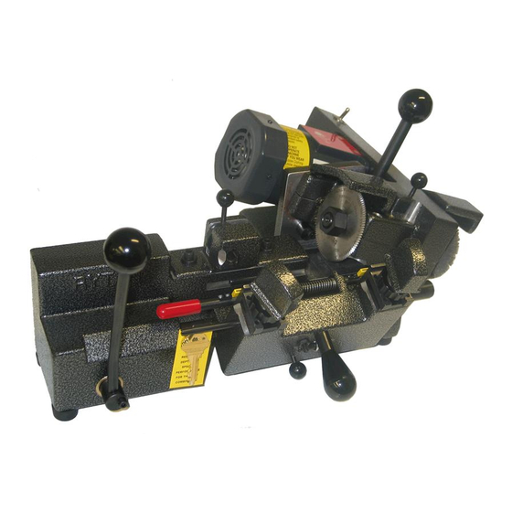
Rytan Mo d el RY2 56 S em i- Au t om a tic Key Du p lic a t ing M a ch in e f or
M edeco ® K ey s, C yl i nd e r Key s an d Au to m o t ive Key s
Ryt an P r odu c t s A r e D e s i g ne d a n d M anufa ct ur ed i n t he U . S.A .
RE AD AN D U NDE RSTA ND TH IS OP E R ATOR ’ S MA N U A L A N D B EC OME
FAMILIAR WI T H YO U R NE W MA C H IN E B EF OR E YOU STA R T C U T T IN G K EYS
RY TA N, IN C . R E SERVE S T HE RI G H T TO M A K E CH A NGE S W IT H OU T N OT I C E . P R I C E S M AY VA R Y F R O M Y O U R D I S T R I B U T O R .
R y t a n , I n c . 1 6 4 8 W . 1 3 4 t h S t . G a r d e n a , C A 9 0 2 4 9 U S A • ( 8 0 0 ) • 4 4 7 • 9 8 2 6 • f a x ( 3 1 0 ) • 2 1 2 • 6 0 0 2
RY39 Auxillary Lamp
Kit is a Extra Cost
Accessory
1
I N C O R P O R A T E D
RY101 Wire Brush
Kit is a Extra Cost
Accessory
Advertisement
Table of Contents

Related Manuals for Rytan RY256


Summary of Contents for Rytan RY256
- Page 1 OP ERATOR ’ S MANUA L Rytan Mo d el RY2 56 S em i- Au t om a tic Key Du p lic a t ing M a ch in e f or M edeco ® K ey s, C yl i nd e r Key s an d Au to m o t ive Key s Ryt an P r odu c t s A r e D e s i g ne d a n d M anufa ct ur ed i n t he U .
-
Page 3: Getting Started
GETTING STARTED Please take time now to read and understand this manual thoroughly before you start cutting keys. Maintain this owner’s manual and review it often, and make it available to others who will use this machine. SAFETY FIRST Do not attempt to operate this machine until you have read thoroughly and understand completely all instructions, rules, etc. - Page 4 M) Maintain a sharp cutter wheel. A dull cutter wheel is not only inefficient but also dangerous. A dull cutter wheel can produce excessive cutting force on a key blank and exceed the machine’s vise jaws clamping force to a point where the key blank could be ripped out of the machine. N) Disconnect machine.
-
Page 5: Mounting The Machine
E) Always cut keys from Bow-to-Tip. NEVER MAKE YOUR FIRST CUT FROM TIP-TO-BOW. The RY256 is specially designed to cut most cylinder keys and U.S. and Foreign automotive keys by operating the machine’s “stick-shift” lever SMOOTHLY from RIGHT-to-LEFT. The key will be cut properly starting at the Bow and ending at the Tip of the key. - Page 6 must flip over both left and right top vise jaws and clamp them in place with the large knurled knobs located below the painted key clamping knobs. Make sure your vise jaws are clean (no chips) and as you secure the top vise jaw in the “step” jaw configuration-be sure to push the back edge of the step top jaw firmly and flat against the stepped face of the bottom vise jaw when tightening the large knurled located below the painted key clamp knob.
- Page 7 “V” and into another adjacent cut. When you have duplicated all the Right cuts lock back your carriage and turn OFF your machine. Cutting Medeco Hi-security keys is simple and easy to do with the Rytan RY256 Key Duplicating machine. Keeping your machine clean and paying attention to detail and following the simple steps outlined above will insure quality Medeco keys cut at maximum profit for you.
- Page 8 Figure 2 CHANGING THE TOP VISE JAWS To change the top vise jaw unscrew the painted key-clamping knob a few turns. Unscrew the large knurled knob located below the painted key-clamping knob a few turns. Slide out the top vise jaw. Look for key cutting chips and brush them away before reinstalling the top vise jaw.
- Page 9 BOTTOM VISE JAW REPLACEMENT FIGURE 3 Remove the top vise jaws. The bottom vise jaws are secured by two #10-32 x ½” long socket head cap screws. Use a 5/32” Allen hex wrench to remove the screws. If you have difficulty accesing the bottom screw you may remove the top plate.
- Page 10 Reinstall the top plate with the (4) #6-32 x ½ screws flush with the top of the top plate- but do no tighten the four screws at this time. Remember to reinstall the top plate with its INDEX MARK in the same location it was before.
- Page 11 8.Clamping Keys Open the vise jaws only wide enough to slide the key in. With the key in all the way into the “throat” of the vise jaws- put your index finger against the key blade as shown below and with moderate force against the key into the vise jaw gently slide the key left and right a few times (about 1/8”...
- Page 12 Ignition key “ridge” will contact the face of the TOP vise jaw. See figure 8 below. Door and trunk key “ridge” will contact the face of the BOTTOM vise jaw. See figure 8 below. See figure 8 below for proper insertion of keys into vise jaws. FIGURE 8...
- Page 13 9.Tip Gauging (Ford double-sided) Operate the full-function key gauges by rotating the key gauge shaft towards you-then push to the right on the key gauge shaft while continuing to rotate the key gauge until the key gauge aligns itself with the tip of the key.
- Page 14 Figure 11 10.Releasing The Carriage For safety purposes- releasing the carriage requires two actions. With your right hand, push down gently on the carriage’s large “tear-drop” knob just enough to move the carriage down reach around with your thumb and index finger and grasp the small round black knob and pull it out – gently lift up on the carriage a small distance and THEN let go of the small round black knob and continue positioning the carriage where you want it to be (you will want to move the carriage to the beginning of the first cut nearest the bow of the key).
- Page 15 (Medeco duplication) The RY256’s stylus can be rotated from the “center” (straight up) position- to the left or to the right. Rotating the stylus is accomplished by moving the small black knob attached to the stylus either to the left or to the right of “center”...
- Page 16 13.ROTATING THE CUTTER HEAD (Medeco duplication) The cutter head must always be rotated in the same direction as the stylus. To rotate the cutter head-Turn the large black round knob and shaft assembly until you “feel” the shaft “detent” (or loosen) into position. It does not matter if you turn the large black knob and shaft in the left direction or in the right direction.
- Page 17 CUTTER HEAD LABEL The label in figure 15 is affixed to your motor-near the large black knob and shaft assembly. FIGURE 15 14. LOCK THE CUTTER HEAD The cutter head must be LOCKED in position when cutting keys –Center, Left, or center Right. PLEASE …...
- Page 18 FIGURE 16 15. CUTTER SHAFT LOCK To remove the cutter you must lock the cutter and cutter shaft in position before using a wrench to remove the cutter. Press DOWN firmly on the cutter shaft lock (small round black knob). While holding the knob down rotate the cutter by hand until the cutter shaft lock “clicks”...
-
Page 19: Replacing The Cutter
Figure 17 REPLACING THE CUTTER Before your replace the cutter - clean off any cuttings from the cutter shaft with a clean rag. Apply a small of white grease to the cutter shaft face, shank, and threads before installing the cutter wheel and Left-Hand Nut. - Page 20 FIGURE 18 Depth is adjusted by moving the stylus forward or backward by means of a hardened, fine threaded Allen set screw. The adjustment is secured by 7/16” Hex Jam Nut. See figure 19 below. To begin the adjustment you must loosen the 7/16” Hex Jam Nut-do not remove it. With your 1/8”...
- Page 21 make your adjustments. Turning the cutter backwards will bump the key blank without cutting it - if the stylus was not adjusted forward enough to miss the key blank. Upon verifying that the cutter wheel misses the key blank – you may switch ON your key machine. Take the 1”...
- Page 22 18. Spacing Adjustment Never adjust the spacing without first adjusting DEPTH. If the depth adjustment is not right- spacing will not be right. Spacing is adjusted by moving the stylus holder left or right. The stylus holder is secured to the machine’s main housing by two 1/ 4-20 Socket Head Cap Screws and washers.
- Page 23 Reinstall the TOP key blank in the Right vise jaw with about 1/32” gap between the bottom shoulder of the key and the left-edge of the vise jaw. Install the BOTTOM key blank in the left vise jaw-flip up the machine’s full function key gauges and carefully top shoulder gauge the left key to the key in the right-hand vise jaw.
- Page 24 Turn the cutter BACKWARDS with your hand and observe which way you must move the stylus holder. Use your small plastic mallet to “nudge” the stylus holder in the direction you want it to go. It is a good idea to verify the cutter position in the “V” cut in the key after every “tap” of the small plastic mallet.
- Page 25 FIGURE 23 Install the other key blank in the Left vise jaw use BOTTOM SHOULDER GAUGING. DO NOT use the machine’s flip up full-function key gauges. NOW flip up the machine’s full-function key gauges and place them in the wide grooves cut in the keys. Adjust the key gauges as necessary by loosening the key gauges’s fastening screws.
- Page 26 Release the carriage and GENTLY bring the keys into contact with the stylus and cutter wheel. Position the keys so the stylus and cutter wheel are nearer to the shoulder of the keys than the center of the blade. Switch ON the key machine. With the cutter spinning use your right hand to apply (momentarily) a gentle to moderate amount of pressure to the carriage creating a very small cutter wheel mark in the right hand key blank.
- Page 27 Remove the cutter guard and observe the pivot stud behind the cutter wheel-notice that it is pointed. The pointed stud is provided on all RY256 key machines as a visual reference point for adjusting the alignment of the cutter wheel in the field. You may have to clean the cutting chips away from the point to see it better.
- Page 28 the key as described. Continue to adjust in very small amounts and make a test key until you are satisfied with the results. When the adjustment is complete retighten the two cutter head screws with your 3/16” Allen Hex Wrench- do not over-tighten these screws.
-
Page 29: Maintenance
You can service virtually anything on your machine yourself. There are no special tools, fixtures or alignment jigs required to install the parts used in this key machine. Because Rytan manufacturers the machines in-house you are assured a supply of new replacement parts and updates for as long as YOU want us to make the machine’s. -
Page 30: Drive Belt
DO NOT LUBRICATE your key machine with LPS-1 or WD-40 in place of number 30 non- detergent motor oil. You may use LPS-1 or WD-40 as a rust preventative in addition to the number 30 non-detergent motor oil. If you only use LPS-1 or WD-40 as your machine’s lubricant you will eventually damage the machine. -
Page 31: Troubleshooting
There is only one way to get good results on consistent bases. Buy a quality-built heavy-duty key machine, don’t abuse it, and keep it well maintained and adjusted at all times. Keep an eye on cutter sharpness, the integrity of the stylus, the fit of the vise jaws, the fit of the key gauge shaft to the carriage, and the fit of the cutter shaft to the bearings. - Page 32 7. Keys don’t always work in the lock when gauged off the bottom shoulder stop. This is a common problem caused by the key blank manufacturers. In recent years many of the key blank manufacturers have stopped paying attention to the bottom shoulder stop on most keys blanks since they are seldom used by the lock cylinder.
- Page 33 2. Your drive belt is coming apart or is frayed. Replace it. 3. Your ball bearing cutter wheel shaft assembly is wearing out. With the machine turned OFF—grab the cutter wheel’s left-hand nut and try to get some movement out of it. There should be absolutely no movement—if there’s movement in the bearings you need to replace the cutter shaft assembly.
- Page 34 You really cut more keys than you thought you did. Often we calculate how many months the cutter lasted instead of how many keys you cut. If you really want to know how long your cutter lasted— keep an accurate inventory of your key blanks—or put a simple mechanical counter on your key machine and you’ll be surprised with results.
- Page 35 Remove the left-hand nut and cutter wheel. Remove the access plate and wire brush if installed on your RY256. Loosen the drive belt tension idler and remove the drive belt. Loosen the two cap screws located on the top front edge of the cutter head – use your 3/16” Allen Hex wrench.
- Page 36 The Carriage Spring Turn the machine over on a piece of thick carpet (you don’t want to damage the power switch located on the front of the machine). Use your 3/16” Allen hex wrench and remove the ¼-20 x ¾” long socket head cap screw that secures the linkage to the “stick-shift”...
- Page 37 burr on the shaft at the edge of the milled notch – remove any burr you may find in this area with your file before trying to remove the carriage shaft. Pull out the carriage shaft. Use a piece of 1” diameter hard wood dowel purchased from your local hardware store. Cut off apiece about 6”...
-
Page 38: Customer Information
Rytan, Inc. provides the following information on warranty and service for the RY100 key-duplicating machine: Warranty Registration The Warranty Registration Form must be filled out and mailed to Rytan, Inc.within TEN days of date of purchase. Failure to do so will VOID the warranty. Payment of Shipping and Handling Charges Payment of all shipping and handling charges are the customer’s responsibility for all warranty work... - Page 39 SOURCES, OR HAVE BEEN SUBJECT TO NEGLECT, ABUSE, MISUSE, OR ACCIDENT (INCLUDING SHIPPING DAMAGES), OR MACHINES WHO’S WARRANTY REGISTRATION FORMS HAVE NOT BEEN MAILED TO RYTAN, INC. WITHIN TEN DAYS OF DATE OF PURCHASE. THIS WARRANTY IS EXCLUSIVE AND REPLACES ALL OTHER WARRANTIES, INCLUDING THOSE OF MERCHANTABILITY AND FITNESS FOR A PARTICULAR PURPOSE.
Need help?
Do you have a question about the RY256 and is the answer not in the manual?
Questions and answers