
Subscribe to Our Youtube Channel
Related Manuals for CTC Union Giersch R20 Series

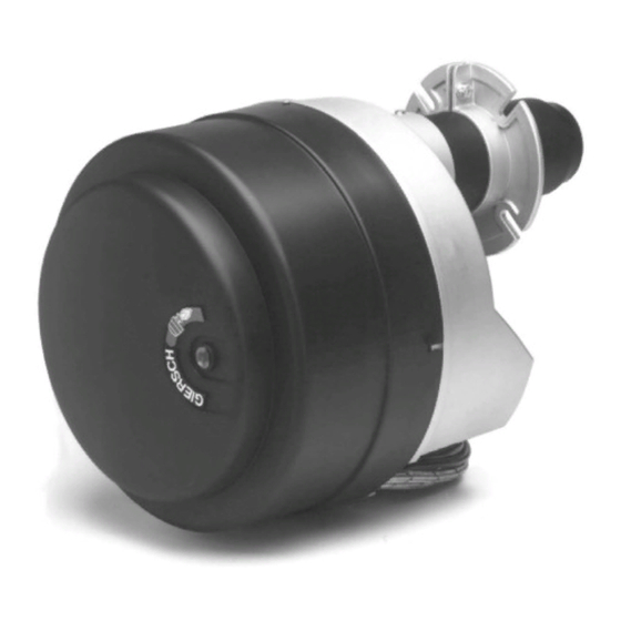
Summary of Contents for CTC Union Giersch R20 Series
- Page 1 Technical Information • Installation Instructions R20 / R30 Issued March 2018 Right reserved to effect technical changes in the interest of product im provement !
-
Page 2: Table Of Contents
Overview ......................3 General information ........................3 Checking scope of delivery and connection data............... 3 Operating instructions ........................ 3 Instruction of operating personnel....................3 Maintenance and customer service ................... 4 Key for code designation ......................4 Technical specifications ......................4 Installation ...................... -
Page 3: Overview
Overview Overview General information The installation of an oil-fired system must conform to extensive regulations and requirements. It is there- fore the duty of the installer to be familiar with all applicable regulations and requirements. Installation, star- tup and maintenance must be performed with utmost care. Fuel oil type EL to DIN 51603 must be used. The burner must not be operated in rooms with high levels of air humidity (laundry rooms), dust or corrosive vapours. -
Page 4: Maintenance And Customer Service
Overview Maintenance and customer service The complete system should be checked once a year for correct functioning and leaks by a representative of the manufacturer or other suitably qualified person. We accept no liability for consequential damage in cases of incorrect installation or repair, the fitting of non- genuine parts or where the equipment has been used for purposes for which it was not intended. -
Page 5: Installation
Installation Installation Installing flange and burner When installing the sliding flange, only tighten screws 1 and 2 otherwise it will not be possible to secure the burner pipe with screw 3. Slide in the burner, adjust to furnace depth and tighten the screws in the following sequence: 3, 4, 5, raising the housing in the process. -
Page 6: Oil Pump
Installation Single pipe system H [m] throughput [mm] [kg/h] bis 2,5 2,5-5,0 5,0-10,0 10,0-23,0 For pure single-pipe operation the bypass stopper must be unscrewed out of the return line opening and the return line opening must be sealed with a gasket and metal stopper. -
Page 7: Function
Function • Remove the sealing plug 4. Danfoss: • Screw in the pressure gauge and adjust the pump pressure with the regulating screw 6. Key to Danfoss pump: 1 = Flow 2 = Return 3 = Pressure tube connection 4 = Pressure measuring connection 5 = Vacuum measuring connection 6 = Pressure adjustment 8 = Magnetic valve... -
Page 8: Flame Monitor With Flame Detector Qrb
Function Error code table Red blink code of „AL“ at Possible cause signal term. 10 lamp (LED) 2 x blinks No establishment of flame at the end of «TSA» - Faulty or soiled fuel valves - Faulty or soiled flame detector - Poor adjustment of burner, no fuel - Faulty ignition equipment 3 x blinks... -
Page 9: Air Volume Adjustment
Function No burner operation LED OFF No heating request Pre-ventilation LED flashing No flame present Burner operation LED continuously on Flame present For maintenance, clean the inspection glass of the KLC 2002 with a clean, lint-free cloth. Never use burner cleaning sprays. -
Page 10: Servomotor
Function Servomotor (version -Z-L, -ZS-L, 2-stage with automatic economy device) The air valve positioning motor adjusts the air valve position or trips the solenoid valve on two-stage burners with air shutoff. Adjustment is via limit switch cams on the positioning drive roller. You can refer to the presetting table for the cam positi- ons for adaptation of the burner to the requisite boiler output. -
Page 11: Oil Control (Optional)
Function Version B (time meter) Time meters are for the purpose of exact acquisition of the burner runtime and are best connected in parallel with solenoid valve Y6. The time meter is available as an accessory part both directly with the burner and as a retrofit kit. - Page 12 Function The following functions can be displayed: Function Display Momentary consumption 0000.00 Momentary consumption 0000.00 Stage 2 Oil volume ◊ 000000 (resettable) ✳ Oil volume 000000 (total) Total operating hours 000000 Number of 000000 burner startups Operating hours 000000 stage 2 Number of 000000 burner startups stage 2...
-
Page 13: Startup
Startup Startup Adjustment tables R20(-AE) Burner Boiler output Nozzle size Nozzle spray angle Oil pump Oil throughput Nozzle stem output where pressure* position ηk = 92% dimension "A“ [kW] [kW] [USgal/h] [°] [bar] [kg/h] [mm] 0.75 60°S 0.85 60°S 1.00 60°S 1.10 60°S... -
Page 14: Table Of Settings R30
R20(-AE) R20-ZS-L Burner output Boiler Nozzle Nozzle Oil pump Oil throughput Nozzle Servomotor Compression output size spray pressure stem throttle where angle position position ηk=92% dimen- dimen- sion "A“ sion "B" [kW] [kW] [USgal/h] [°] [bar] [bar] [kg/h] [kg/h] [mm] [mm] [mbar] [mbar] 0.75... -
Page 15: Design
Design Design R20(-V) Seq. No. Designation Order No. Diaphragm plate with retainer and twin electrode for WLE 47-90-21254 Twin electrode for WLE 33-50-10711 Nozzle on request Ignition cable 640 mm long 47-50-26741 Nozzle stem for R20 32-90-11509 Nozzle stem with oil preheater and cable for R20-V 52-90-21342 Fan dia.146 x 62 mm 32-90-10139... - Page 16 Design R20-ZS-L(-AE)- Seq. No. Designation Order No. Diaphragm plate with twin electrode (for fan-assisted air heater) 47-90-21254 Twin electrode for WLE 33-50-10711 Nozzle on request Ignition cable 640 mm long 47-50-26741 Nozzle stem 32-90-12650 Fan dia.146 x 62 mm 32-90-10139 Lower section, control box 37-90-11310 Control unit LMO24...
-
Page 17: Exploded Drawing And Spare Parts/Parts List R30
Design R30-AE Seq. no. Designation Order No. Retarding disc with retainer and twin electrode 33-90-10708 Twin electrode 33-50-10711 Nozzle on request Ignition cable 640 mm long 47-50-26741 Nozzle stem 33-90-10706 Plug unit, 7-pin, black/brown 37-50-11015 Socket unit 7-pin black/brown 37-50-20731 Flame detector KLC 47-90-28177 Lower section, control unit... - Page 18 Design R 30-Z-L Seq. No. Designation Order No. Retarding disc with retainer and twin electrode 33-90-10708 Twin electrode 33-50-10711 Nozzle on request Ignition cable 640 mm long 47-50-26741 Nozzle stem 33-90-10706 Plug unit 4-pin, black/green 37-50-11143 Plug unit, 7-pin, black/brown 37-50-11015 Socket unit, 11-pin, 37-90-11135...
-
Page 19: Service Instructions/Dimensions
Service instructions/dimensions Service instructions/dimensions Boiler/burner conditioning Precise boiler/burner conditioning is necessary for low-emission and energy-saving combustion. For this purpose a burner is assigned to the boiler in accordance with the working ranges (Page 28) and in consi- deration of the resistance at the heating gas face. The insertion depth of the burner tube is optimally adju- sted by way of the sliding flange to the relevant combustion chamber. -
Page 20: Service Position
Service instructions/dimensions Servicing position R 20 / R 30 Risk of injury by fan wheel during activation in ser- vice position. • Release quick-release locks and detach base plate. • Suspend base plate with retaining buttons in cross recesses of housing. Control dimensions for the ignition R 20 electrode... -
Page 21: Wiring Diagrams
Service instructions/dimensions Wiring diagram R20 R20-AE... - Page 22 Service instructions/dimensions R20-V R20-ZS-L...
- Page 23 Service instructions/dimensions R30-AE R30-Z-L...
- Page 24 Service instructions/dimensions Key: Flame failure controller KLC Socket unit burner (4-pin, bl/green) Ext. fuse boiler control 6.3 AT/max.10 AF X81,82,83,84 Single-pole terminal strip Ext. temp. controller Actuating drive Ext. temp. controller 2nd stage Oil solenoid valve Safety temperature limiter Oil solenoid valve 2nd stage Ext.
-
Page 25: Troubleshooting
Service instructions/dimensions Troubleshooting Fault Cause Elimination Fuse defective Replace Safety thermostat locked Unlock Temperature of the controller adjustment excee- After temperature drop make new attempt to start Control box defective Replace Motor defective Replace Burner motor will not Oil preheater: heater or thermostat enable Replace defective Air valve positioning motor does not open or... -
Page 26: Burner Overall Dimensions / Boiler Connection Dimensions
Burner overall dimensions / boiler connection dimensions (All dimensions in mm) R 20 90° min. 427 R 30 R 20 R 30 Pipe outer dia. d Hole circle dia. k 170(140-180) 170-200 Outside dia. f min. 411 Working ranges R 2 0 R 2 0 - V R 2 0 -AE D u r c h s a t z [ k g / h ]...
Need help?
Do you have a question about the Giersch R20 Series and is the answer not in the manual?
Questions and answers