Table of Contents
Advertisement
Quick Links
Advertisement
Table of Contents

Subscribe to Our Youtube Channel
Related Manuals for Innova OnLine Series

Summary of Contents for Innova OnLine Series
- Page 1 USER MANUAL ONLINE UPS INNOVA 6-10K TOWER...
-
Page 2: Table Of Contents
NOTE: 1. Safety and EMC Instructions .............. 1 1.1 Installation..................1 1.2 Operation ..................2 1.3 Maintenance, servicing and faults........... 2 1.4 Transport ..................3 1.5 Storage .................... 3 1.6 Standards ..................4 2. Description of Commonly Used Symbols ......... 5 3. - Page 3 7.3 Trouble Shooting In Else Cases............ 50 8. Battery Maintenance ................51 9. Communication Port................52 9.1 USB Interface ................52 9.2 Dry contact Interface ..............52 9.3 Intelligent slot................. 52 10. Software .................... 53...
-
Page 4: Safety And Emc Instructions
1. Safety and EMC Instructions Please read carefully the following user manual and the safety instructions before installing the unit or using the unit! 1.1 Installation This is permanently connected equipment, and it must be ★ installed by qualified maintenance personnel. Condensation may occur if the UPS is moved directly from a ★... -
Page 5: Operation
With the installation of the equipment, the sum of the leakage ★ current of the UPS and the connected load does not exceed 5% of rated value of input current. Do not block ventilation openings in the UPS’s housing. Ensure ★... -
Page 6: Transport
Before carrying out any kind of service and/or maintenance, ★ isolate UPS and disconnect the batteries. Verify that no current is present and no hazardous voltage exists in the capacitor or BUS capacitor. Batteries must be replaced only by qualified personnel. ★... -
Page 7: Standards
1.6 Standards * Safety IEC/EN 62040-1-1 * EMI Conducted Emission......:IEC/EN 62040-2 Category C3 Radiated Emission......:IEC/EN 62040-2 Category C3 * EMS ESD...........:IEC/EN 61000-4-2 Level 3 RS.............:IEC/EN 61000-4-3 Level 3 EFT............:IEC/EN 61000-4-4 Level 4 SURGE..........:IEC/EN 61000-4-5 Level 4 CS……………………………………...:IEC/EN 61000-4-6 Level 3 MS……………………………………..: IEC/EN 61000-4-8 Level 3 Voltage Dips………………………..: IEC/EN 61000-4-11... -
Page 8: Description Of Commonly Used Symbols
2. Description of Commonly Used Symbols Some or all of the following symbols may be used in this manual. It is advisable to familiarize yourself with them and understand their meaning:... -
Page 9: Introduction
3. Introduction This On-Line series is an uninterruptible power supply incorporating double-converter technology. It provides perfect protection specifically for computer equipments, communication servers, and data centers. double-converter principle eliminates mains power disturbances. A rectifier converts the alternating current from the utility power to direct current. -
Page 10: Electrical Specifications
Outstanding adaptability to the worst mains input condition. Extra wide input voltage, frequency range and waveform, avoid excessive dissipating limited battery energy. Internal charger could be up to 4Amps to decrease recharging time of battery. Optional external large charging current charger which is up to 12Amps could be supplied. -
Page 11: Operating Environment
Load type PF 0.5~1, lagging < 2% @ full linear load THDV <5% @ full non linear load In Line mode**: 10 min 105~125% 1 min 125~150% 10 s >150% Overload >170% In Battery mode: 2 min 105~125% 30 s 125~150% >150% *Derating to 90% when the output voltage is adjusted to 208VAC. -
Page 12: Typical Backup Time (Typical Values At 25°C In Minutes)
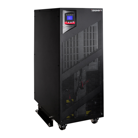
3.4 Typical backup time (Typical values at 25° C in minutes) Model No. 100 % Load 50 % Load 3.5 Dimensions and weights Dimensions W×H×D Net Weight Model No. (mm) (kg) 260 x 708 x 550 260 x 708 x 550 260 x 708 x 550 10KS 260 x 708 x 550... - Page 13 Fig. 3-1 Front view of 6K(S)/10K(S)
- Page 14 6K(S) 10K(S) Fig. 3-2 Back View of 6K(S)/10K(S)
-
Page 15: Installation
4.1 Moving to the installation site The Innova series UPS has wheels making it easy to move the UPS to the installation site after it has been unpacked. However, if the receiving area is far from the installation site, it is recommended to move the UPS by using a pallet jack or a truck before unpacking the UPS. -
Page 16: Input And Output Power Wires And Protective Earth Ground Installation
Check all packaging materials to ensure that no items are missing. The shipping package contains: ● A UPS ● A user manual ● A communication cable ● A parallel cable ● A parallel port cover plate ● Terminal connectors 12pcs Inspect the appearance of the UPS to see if there is any damage during transportation. - Page 17 Fig. 4-5 Additional stability 4.3.2 Installation For safety, please cut off the mains power switch before installation! Use cable cross section and protective device specification Model Protective earthing conductor (10AWG) 10 mm (6AWG) Min cross section Input L, N, G Min conductor cross section (10AWG) 10 mm...
- Page 18 External Battery Cabinet Breaker in Positive Pole(+), Negative pole(-), 60A/240VDC 90A/240VDC Neutral Pole Backfeed protection device A 2-pole disconnection device with 80A/250VAC, less than 15s break time and min. 1.4mm clearance should be used in final installation for backfeed protection. Torque for fixing above terminals 3.95~4.97Nm (35~44 1b in)
- Page 19 8) Connect other input and output wires to the corresponding input and output terminals according to the following diagram. 9) It is recommended to use the accessorial terminal connectors which can be compacted on the wires tightly, to ensure the connection between the wires and the terminal block is reliable.
-
Page 20: Operating Procedure For Connecting With The External Battery
14) If it is necessary to connect the inductance load such as a monitor or a laser printer to the UPS, the start-up power should be used for calculating the capacity of the UPS, as its start-up power consumption is too big to make the UPS which capacity is small fail easily. -
Page 21: Epo Connection
Set the external battery pack breaker in “OFF” position and connect the 20 pieces of batteries in series. Connect the external battery pack to the battery terminals. Check the polarity of connection is correct. Set the breaker of the battery pack in the “ON” position. Set the mains input breaker in the “ON”... -
Page 22: Operation
5. Operation 5.1 Display Panel The UPS has a four-button dot matric LCD with dual color backlight. Standard back-light is used to light up the display with white text and a blue background. When the UPS has a critical alarm, the backlight changes the text to dark amber and the background to amber. - Page 23 When displaying default UPS status summary Enter main screen, press this button for >1s to enter the menu main menu tree Press this button for >1s to exit the present menu Exit main to default system status display menu without menu executing a command or changing a setting Press this button for >100ms&<1s to scroll up the...
- Page 24 Note : : : : ●: Lightened constantly : #1-#4 Lightened circularly △ : Flashing ★ ↑: Depended on the fault/warning status or other status Table 5-3 Alarm definition UPS condition Buzzer status Fault active Continuous Warning active Beep every second Battery output Beep every 4 seconds Bypass output...
-
Page 25: Operating Mode
Fig. 5-2 The default LCD display The more detailed operation of LCD is illustrated in the chapter of 5.5. 5.2 Operating mode The different graphic symbol could be displayed corresponding to current operating mode or status. 5.2.1 Line mode The example of LCD display in Line mode is shown in the following diagram. - Page 26 5.2.2 Battery mode The example of LCD display in battery mode is shown in the following diagram. Fig. 5-4 Battery mode When the UPS is running in battery mode, the buzzer beeps once every 4 seconds. If the button on the front panel is pressed for more than 1 second again, the buzzer will stop beeping (in silence mode).
- Page 27 5.2.4 Bypass without output The LCD display in bypass mode without output is shown in the following diagram. Fig. 5-6 Bypass mode without output mode 5.2.5 HE mode (High Efficiency It is also called economy mode. After the UPS is turned on, the power used by the load is supplied from the utility power via internal filter while the utility power is in normal range, so the high efficiency could be gained in the HE mode.
- Page 28 It is attention that the transfer time of UPS output from HE mode to battery mode is about 10ms. But it is still too long for some sensitive load. 5.2.6 Converter mode In converter mode, the UPS would free run with fixed output frequency (50Hz or 60Hz).
- Page 29 Fig. 5-9 Warning 5.2.8 Fault When the fault occurs, it illustrates that some fatal problems happened, the UPS would directly cut off the output or transfer to bypass, and keep alarming. The backlight of LCD would also turn to red. The detailed fault table is shown in chapter of 7.
- Page 30 Fig. 5-11 Overload While doing the battery test, LEDs would be lighted circularly, and the symbol of battery test would be shown on the display. Fig. 5-12 Battery test And if the battery status detected is “bad battery detected” or “battery disconnected”, the symbol of battery failure would be shown and UPS would alarm.
-
Page 31: Turning On And Turning Off Ups
5.3 Turning on and Turning off UPS Attention: The UPS could only be turning on while connecting with the utility at the first time. Attention: Please switch off the connected loads first before turning on the UPS, and switch on the loads one by one after the UPS is turned on. -
Page 32: Lcd Operation
5.3.3 Turning off UPS with utility To turn off the inverter of UPS by pressing button continuously for more than 1 seconds and the buzzer will beep for 1s. The UPS will turn into Bypass mode at once. When completing the above action, UPS output voltage is still present. - Page 33 Fig. 5-14 Main menu tree 5.4.2 The UPS status menu By pressing on the menu of “UPS status”, the display would enter the next UPS status menu tree. The content of UPS status menu tree is same as the default UPS status summary menu.
- Page 34 Fig. 5-15 UPS status menu tree 5.4.3 The event log menu By pressing on the menu of “Event log”, the display would enter the next event menu tree. All the old event, alarm and fault have been recorded here. The information includes the illustration, the event code, and the operating time of UPS when the event happened.
- Page 35 Fig. 5-16 Event menu tree 5.4.4 The measurement menu By pressing on the menu of “Measurement”, the display would enter the next measurement menu tree. A lot of detailed useful information could be checked here, Ex. the output voltage and frequency, the output current, the load capacity, the input voltage and frequency, etc.
- Page 36 Main menu tree UPS status Measurement menu tree Ambient Temperature DC Bus 29.1 ºC 83.4 ºF 226.3 225.9 Event log By press >1s Output Battery Measurement 1130 228.2 By press <1s By press <1s Output Input 24.9 220.4 60.0 Output 220.4 60.0 Fig.
- Page 37 status, then UPS would stop alarm and recover to Bypass model. And UPS needs be turned on by manual operation. Reset error status: when fault occurs, UPS would keep in Fault mode and alarm. To recover to normal status, enter this menu to reset error status, then UPS would stop alarm and recover to Bypass mode.
- Page 38 Fig. 5-19 clear EPO status 5.4.6 The identification menu By press on the menu of “Identification”, the display would enter the next identification menu tree. The identification information includes UPS serial number, firmware serial number, model type, would be shown here. By press >1s, the display would return the last main menu tree.
- Page 39 Fig. 5-20 Identification menu tree 5.4.7 The setting menu Please contact your local distributor for further information before using the settings. Some settings would change the specification, and some settings would enable or disable some functions. The unsuitable option set by user may result in potential failures or protecting function loss, even directly damage the load, battery or UPS.
- Page 40 Setting menu tree Control commands Battery quantity from serial port <20> <enabled> Main menu tree Clear event log EPO input polarity Total events: 50 <open> LCD contrast HE voltage high limit Identification <+0> <+10%> Password: AAAA By press <1s By press >1s User password HE voltage low limit...
- Page 41 By press on the menu of “Identification”, the display would enter the next setting menu tree if “User password” is disabled. If “User password” is enabled, the user should enter the password by press , and , then enter the next setting menu tree. Table 5-1 Submenu item Optional Values...
- Page 42 Example: set rated output voltage value Fig. 5-22 Set rated output voltage value...
-
Page 43: Special Function
6. Special function The series UPS has some special functions, which could satisfy some special application of user. And the functions have own features, please contact your local distributor for further information before using the function. 6.1 HE function 6.1.1 Brief introduction of HE function If HE function is set to enable, after the UPS is turned on, the power used by the load is directly supplied from the utility power via internal filter while the utility power is in normal range, so the high... -
Page 44: Converter Function
6.2 Converter function 6.2.1 Brief introduction of Converter function In converter mode, the UPS would free run with fixed output frequency (50Hz or 60Hz). Once the mains is loss or abnormal, the UPS would transfer to Battery mode and the load is supplied continuously. - Page 45 6.3.2 Parallel installation and operation How to install a new parallel UPS system: Before installing a new parallel UPS system, user need to prepare the input and output wires, the output breaker, and the parallel cable. Users need to use a standard 25-pin communication cable, which should have 25 cores, corresponding stitches and shield, as the UPS parallel cable.
- Page 46 Fig. 6-1 Input and output Terminal Block wiring diagram...
- Page 47 TO UTILITY Main mechanical or static switch Main I/P Breaker Main O/P Breaker TO LOAD Fig. 6-2 Parallel System Installation Diagram 10) Do not switch on the output breaker of each UPS, switch on the input breaker of the each UPS, the UPS should work in bypass with output, observe their display to check if there are any warning or fault information, measure the output voltage of each UPS separately to check if the voltage difference between...
- Page 48 13) Press the button of one UPS, each UPS would start to turn on, after turning on, the UPSs should work parallel in the Line mode. How to join a new UPS to a parallel system: First the parallel system must be installed one main maintenance mechanical switch or static switch.
- Page 49 Set the main maintenance switch or static switch from “UPS” to “BPS”, switch off the main output breaker, and the UPSs would shut down. Ensure the UPSs shut down totally, set the UPS own maintenance switch from “BPS” to “UPS” and screw the maintenance cover plate back again.
-
Page 50: Trouble Shooting
7. Trouble Shooting If the UPS system does not operate correctly, first check the operating information on the LCD display. Please attempt to solve the problem using the table below. If the problem still persists, consult your dealer. 7.1 Trouble Shooting According To Warning Indication Problem Displayed Possible cause Remedy... - Page 51 Battery DC Over Voltage Battery voltage is Check if the battery quantity is higher than normal right. value Over Charge Battery is over The UPS would transfer to charged battery mode automatically, and after the Battery voltage is normal and the mains is normal, the UPS would retransfer to Line mode automatically again.
-
Page 52: Trouble Shooting According To Fault Indication
Parallel in HE mode HE function is HE function is forbidden in enabled in parallel parallel system. system Parallel load unbalance UPS internal fault Consult dealer. 7.2 Trouble Shooting According To Fault Indication Problem Displayed Possible cause Remedy Inverter Overload Fault Overload Check the loads and remove some non-critical loads. - Page 53 Fatal EEPROM Fault UPS internal fault Consult dealer. Cable male and female The parallel cable is Check the parallel cable. disconnected fault disconnected 7.3 Trouble Shooting In Else Cases Problem Possible cause Remedy No indication, no No input voltage Check the building wiring and warning tone even input cable.
- Page 54 8. Battery Maintenance Battery replacement should be performed by qualified personnel. This series UPS only requires minimal maintenance. The battery used for standard models are value regulated sealed lead-acid maintenance free battery. These models require minimal repairs. The only requirement is to charge the UPS regularly in order to maximize the expected life of the battery.
- Page 55 9. Communication Port 9.1 USB Interface The USB port is compliance with USB 1.1 protocol for its communication software. 9.2 Dry contact Interface This series UPS has independent dry contact interface. Please contact your local distributor for details. The following is the pin assignment and description of DB-9 connector.
- Page 56 10. Software Free Software Download – WinPower WinPower is a UPS monitoring software, which provides user-friendly interface to monitor and control UPS. This unique software provides safely auto shutdown for multi-computer systems while power failure. With this software, users can monitor and control any UPS on the same LAN, which communicated with local computer through RS232 or USB protocol, no matter how far from the UPSs.
- Page 57 614-09910-00...
Need help?
Do you have a question about the OnLine Series and is the answer not in the manual?
Questions and answers