Table of Contents
Advertisement
Quick Links
Advertisement
Table of Contents

Summary of Contents for Pentek 4283
- Page 1 (217) 352-9330 | Click HERE Find the Pentek 4283 at our website:...
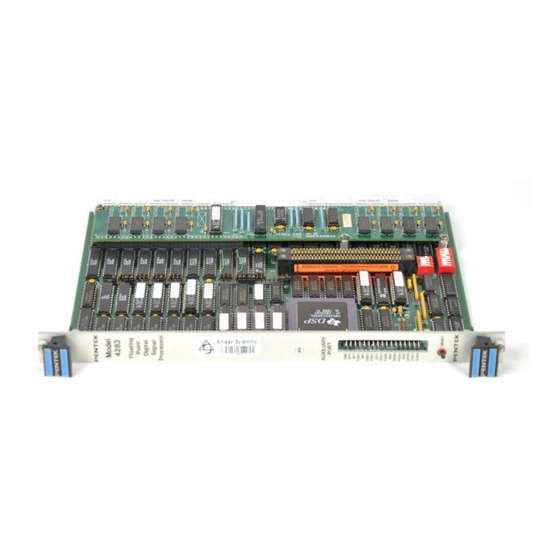
- Page 2 P en te k M o d el 4 28 3 O p e ra t in g M a n ua l P a g e 1 OPERATING MANUAL MODEL 4283 TMS320C30 DSP-Based MIX Baseboard for VMEbus Systems Pentek, Inc.
- Page 3 The obligation of Pentek arising from a warranty claim shall be limited to repairing or at its option, replacing without charge, any product which in Pentek’s sole opinion proves to be defective within the scope of the warranty.
-
Page 4: Table Of Contents
Table of Contents P en te k M o d el 4 28 3 O p e ra t in g M a n ua l P a g e 3 Table of Contents Page Chapter 1: Overview Introduction............................9 System Configuration ........................... - Page 5 P ag e 4 P e nt ek M o d el 4 2 8 3 O pe ra ti n g M a n ua l Table of Contents Page Selecting Bus Arbiter Operation - Level 3..................20 Table 2-6: Bus Arbiter Jumpers Installed - Level 3 ..............20 Figure 2-7: J7 Configured for Bus Arbiter Operation ..............
- Page 6 P en te k M o d el 4 28 3 O p e ra t in g M a n ua l P a g e 5 Table of Contents Page VMEbus Address Modifier Register -'C30 Address 0x0080 0001 (Write Only)......31 Table 3-5: Interrupt Status Register -’C30 Address 0x0080 0800..........
- Page 7 Table 4-4: IACK Vector Register - VMEbus Address A16 Base....... 43 Chapter 5: MIX Expansion Bus Introduction ............................45 MIX Baseboard - Model 4283 ......................45 Expansion Modules (MIX modules) ....................45 MIX Bus Connector Signals....................... 46 Table 5-1:MIX Bus Signals ........................ 46 MIX Module Interface Timing ......................
- Page 8 Writing Programming Code to the EPROM................... 65 Table 7-3: Bus Grant Bypass Jumpers ..................... 65 Appendix A: Programming Example MIX Module Interrupt Service Routine..................A-1 Appendix B: Model 4283 Bootcode General Information.......................... B-1 asm.bat..........................code page - 1 prom30.cmd (Linker Command File................code page - 2 prom30.asm (TMS320C30)....................
- Page 9 P ag e 8 P e nt ek M o d el 4 2 8 3 O pe ra ti n g M a n ua l Table of Contents Page This page is intentionally blank Rev.: G.1 Artisan Technology Group - Quality Instrumentation ... Guaranteed | (888) 88-SOURCE | www.artisantg.com...
-
Page 10: Chapter 1: Overview
This manual will describe the installation and operation of the Model 4283 in several typical VMEbus environments. System Configuration The Model 4283 can be tailored to many different types of systems. Here are a few of the typical application environments: Stand-alone... - Page 11 EPROM byte manipulation are included. SwiftNet Pentek’s SwiftNet is a software product that supports a network of distributed VMEbus systems connected via Ethernet to a host com- puter, such as a SUN workstation or PC-AT. All software develop- ment tools are run on the host with remote target access provided transparently to the user.
-
Page 12: Specifications
Pente k Mo de l 4 28 3 Ope rating Manual Page 11 Specifications Processor: Texas Instruments TMS320C30 Processor Clock: Standard: 32 MHz Option 400: 40 MHz Dual-Port DRAM: Size: Standard: 256k x 32 (1 MByte) Option 002: 1M x 32 (4 MBytes) Option 007: 2M x 32 (8 MBytes) Arbitration:... -
Page 13: Block Diagram
Pe ntek Mo de l 42 83 Ope rating Manual Block Diagram The block diagram of the Model 4283 is shown below. Each of the major elements will be described below. Each element which appears in the TMS320C30 address map has the 'C30 hex address shown next to it. -
Page 14: Primary Data And Address Bus
This register is addressable in A16 space on the VMEbus and controls reset and interrupt functions to the TMS320C30. 1.5.5 Single Level Bus Arbiter When enabled, the Model 4283 can be placed in slot 1 and function as a VMEbus arbiter for bus requests on level 3. 1.5.6 Interrupt Handler The Model 4283 will respond to VMEbus interrupts on any of 7 levels and interrogate the interrupt generator with interrupt acknowledge bus cycles. -
Page 15: Eprom
1.5.10 VMEbus Master Interface The Model 4283 can access data on the VMEbus by performing reads and writes in A16, A24, and A32 address space with data widths of 8, 16, and 32 bits. The bottom 24 bits are directly addressed by the TMS320C30 while the upper 8 bits are determined by the Page Register. -
Page 16: Chapter 2: Installation
These modules and the MIX interface system are described in Appendix A of this manual. It is recommended to wait until the Model 4283 has been successfully installed by itself before attaching any expansion modules since this would make access to the switches and jumpers more difficult. - Page 17 Page 16 Pe ntek Mo de l 42 83 Ope rating Manual Figure 2-2: Model 4283 - Component, Switch and Jumper Block Placement Rev.: G.1 Artisan Technology Group - Quality Instrumentation ... Guaranteed | (888) 88-SOURCE | www.artisantg.com...
-
Page 18: Selecting The Host Control & Iack Vector Register Base Address
This 1k region is divided into sixteen 64-byte locations, one of which is selected by setting four jumpers on jumper block J4. If there is more than one Model 4283 in a card cage, these jumpers must be set to uniquely configure a different base addresses for the 64- byte region on each board. -
Page 19: Selecting Vmebus Interrupter Level
(IACK cycle). This requires that the interrupter Figure 2-4: Model 4283 - Jumper block recognizes a 3-bit IACK address and J1 shown with jumpers installed for sends an 8-bit IACK Vector over the... -
Page 20: Selecting Vmebus Interrupt Handler Level
VMEbus timeout bit, the Host Control Register and VMEbus lines IRQ6 and IRQ7. Figure 2-5: Model 4283 - Jumper Block J4 configured for Host Control Register, Rev.: G.1 Artisan Technology Group - Quality Instrumentation ... Guaranteed | (888) 88-SOURCE | www.artisantg.com... -
Page 21: Selecting Vmebus Bus Request Level - Bus Master Interface
Selecting Bus Arbiter Operation - Level 3 The Model 4283 can act as a VMEbus bus arbiter on level 3 when installed in slot 1 of the VMEbus cage. The arbiter monitors the BBSY line, the BG3IN and BR0 - BR3 lines, and... -
Page 22: Sysrst Input & Output Jumpers
Pente k Mo de l 4 28 3 Ope rating Manual Page 21 SYSRST INPUT & OUTPUT Jumpers If the Model 4283 is to drive the VMEbus SYSRST signal then jumper J7-2,19 must be installed as shown to the right (the SYSRST OUTPUT jumper). -
Page 23: Factory Default Jumper Settings
Pe ntek Mo de l 42 83 Ope rating Manual 2.11 Factory Default Jumper Settings As shipped by the factory, the Model 4283 has the following default jumper settings: DRAM Base Address: 0x0000 0000 EPROM Mode selected Interrupt Requester Level: None... - Page 24 2.11 Factory Default Jumper Settings (continued) Figure 2-11: Model 4283 - Factory Default Jumpers (4 MB Dram Option) Figure 2-12: Model 4283 - Factory Default Jumpers (8 MB Dram Option) Rev.: G.1 Artisan Technology Group - Quality Instrumentation ... Guaranteed | (888) 88-SOURCE | www.artisantg.com...
- Page 25 Page 24 Pe ntek Mo de l 42 83 Ope rating Manual This page is intentionally blank Rev.: G.1 Artisan Technology Group - Quality Instrumentation ... Guaranteed | (888) 88-SOURCE | www.artisantg.com...
-
Page 26: Chapter 3: Tms320C30 Memory Map
Chapter 3: TMS320C30 Memory Map Introduction There are two points of reference for memory resources of the Model 4283: the view from the TMS320C30 (referred to as the 'C30 Memory Map) and the view from the VMEbus (the VMEbus Memory Map). This chapter covers the 'C30 Memory Map and describes the various registers and memory resources and how they are accessed and utilized by TMS320C30. - Page 27 Page 26 Pe ntek Mo de l 42 83 Ope rating Manual Table 3-2: TMS320C30 Memory Map Address Range Description Section Page 0x0000 0000 - 0x0000 7FFF EPROM - 32k x 32 Section 3.3 Page 25 0x0000 8000 - 0x000F FFFF 31 Images of EPROM - Each 32k x 32 0x0010 0000 - 0x0010 FFFF STATIC RAM - 64k x 32...
-
Page 28: Tms320C30 Control Register - Read/Write @ 'C30 Address 0X0080 0000
Page 58, for more details. A schematic of the reset circuitry is shown in Figure 3-1, below. Figure 3-1: Model 4283 - Reset Circuitry Schematic Rev.: G.1 Artisan Technology Group - Quality Instrumentation ... Guaranteed | (888) 88-SOURCE | www.artisantg.com... -
Page 29: Iack1, Iack2 And Iack3
TRSEL0 through TRSEL3 (Transfer Select Bits) - Bits 5, 6, 8, and 9 The TRSEL bits determine the memory cycle operation of the Bus Master Interface of the Model 4283. This interface allows the unit to access the VMEbus for read, write, and interrupt acknowledge cycles. Data transfers for reads and writes may be 8, 16, or 32-bits wide, thus supporting many different types of VMEbus devices. -
Page 30: Longword (32-Bit) Memory Cycle
The TRSEL bits should be set up prior to conducting bus cycles and may be changed at any time by writing a new pattern. The bit definitions for these bits is shown in Table 3-4, below. Table 3-4: Model 4283 - Transfer Select (TRSEL) Bit Functions TRSEL TRSEL Description COMMENTS... -
Page 31: Word (16-Bit) Memory Cycle (Double Cycle)
This bit controls the LOCK function for VMEbus memory cycles performed by the Bus Master Interface. Once the Model 4283 is granted access to the bus by the bus arbiter, it asserts the BBSY (bus busy) line on the backplane. If the LOCK bit is set high, the BBSY line is not released until the LOCK bit is set low. -
Page 32: Interrupt Status Register - 'C30 Address 0X0080 0800
Name NOT USED Each time a VMEbus memory cycle is performed by the Model 4283, these six AM bits drive the six AM lines on the VMEbus. The AM codes are used to define categories of addressing modes as defined in Table 3-7, on the next page. -
Page 33: Page Address Register - 'C30 Address 0X0080 0002 (Write Only)
Master Interface and the MIX Expansion Interface. It is also used to select one of the three MIX Expansion modules. The bit definition is shown in Table 3-8, below. Table 3-8: Model 4283 - Page Address Register - ‘C30 Address 0x0080 0002 - Write Only 31-18 used... -
Page 34: Vmebus Iack Address Register - 'C30 Address 0X0080 0003 (Write Only)
See Section 7.6, Page 61, for a complete description of interrupt handling. Table 3-9: Model 4283 - VMEbus IACK Address Register - ‘C30 Address 0x0080 0003 - Write Only D31 - D3 IACK LEVEL not used IACK A03... -
Page 35: C30 Internal Ram - 'C30 Address 0X0080 9800 Through 0X0080 9Fff
VMEbus IACK Cycle Address - 'C30 Address 0x0080 A000 through 0x008F FFFF When performing an IACK cycle as a VMEbus Bus Master, the Model 4283 reads from anywhere within this address region to retrieve the IACK vector from the interrupting device. -
Page 36: Chapter 4: Vmebus Memory Map
Page 35 Chapter 4: VMEbus Memory Map Introduction This chapter describes the view of the Model 4283 from the VMEbus which consists of three elements: the dual-ported DRAM, the Host Control Register, and the IACK (interrupt acknowledge) Vector Register. VMEbus Addresses VMEbus address bits A1 through A31 are implemented as 31 separate bus lines. -
Page 37: Vmebus Memory Map
2) A24 or A32 memory space for the DRAM (depending on AM codes used). The three memory maps below show how the Model 4283 appears to the VMEbus. Note that A16 space addresses are expressed with 4 hex digits, A24 addresses with 6 digits, and A32 addresses with 8 digits. -
Page 38: A32 Dram Access
(continued) 4.4.1 A32 DRAM Access The Model 4283 will respond to 32-bit addressing for Address Modifier codes (AM Codes) of 0x000E, 0x000D, 0x000A, and 0x0009. Switches SW1 and SW2 are shown below with the address bit correspondence. The switches should be set for the ‘open’ position to match an address bit = 1, and to the ‘closed’... -
Page 39: A32 Dram Access - 8 Mbyte Option
Page 38 Pe ntek Mo de l 42 83 Ope rating Manual Addressing the DRAM (continued) 4.4.1.1 A32 DRAM Access - 8 MByte Option The address range of the 8MB DRAM in 32-bit VMEbus address space is given below in hex: The first three hex digits are shown decomposed into four binary bits. -
Page 40: A32 Dram Access - 1 Mbyte Option
Figure 4-2, below. Remember, the arrows point to the depressed position (indicated by the black dots in the drawing). Figure 4-2: Model 4283 - Base Address Switches (A32) - DRAM_base = 9B60 0000 Rev.: G.1 Artisan Technology Group - Quality Instrumentation ... Guaranteed | (888) 88-SOURCE | www.artisantg.com... -
Page 41: A24 Dram Access
(continued) 4.4.2 A24 DRAM Access The Model 4283 will respond to 24-bit addressing for Address Modifier codes (AM Codes) of 0x0039, 0x003A, 0x003D, and 0x003E. Switch SW1 is shown below with the corresponding address bit correspondence. The switch should be set for the ‘open’ position to match an address bit = 1, and to the ‘closed’... -
Page 42: A24 Dram Access - 4 Mbyte Option
0x0040 0000H. The address range will be from 0x0040 0000 to 0x007F FFFF. The address switch SW1 should be set as shown below. Figure 4-4: Model 4283 -A24 DRAM_base = 0x0040 0000 Rev.: G.1 Artisan Technology Group - Quality Instrumentation ... Guaranteed | (888) 88-SOURCE | www.artisantg.com... -
Page 43: Host Control And Iack Vector Registers
The Host Control Register allows a VMEbus Bus Master to control the reset and interrupt lines into the 'C30. The IACK Vector Register is an 8-bit register loaded from the VMEbus which stores a vector which the Model 4283 sends in response to an interrupt acknowledge cycle. -
Page 44: Hostrst - Bit 0
VMEbus uses to identify the source of an interrupt. This vector is an 8-bit value which is placed on the VMEbus data bus lines D7 through D0 in response to an IACK cycle. Table 4-4: Model 4283 - IACK Vector Register - VMEbus Address A16 Base 15 - 2 Name not used Rev.: G.1... - Page 45 Page 44 Pe ntek Mo de l 42 83 Ope rating Manual This page is intentionally blank Rev.: G.1 Artisan Technology Group - Quality Instrumentation ... Guaranteed | (888) 88-SOURCE | www.artisantg.com...
-
Page 46: Chapter 5: Mix Expansion Bus
MIX Baseboard - Model 4283 The baseboard is the Model 4283 Board which is a full size VMEbus board in a standard 6U format (160mm x 233 mm). It occupies one standard slot position (0.8 inches of horizontal space) in a VMEbus card cage. -
Page 47: Mix Bus Connector Signals
In general, each expansion module occupies one 0.8" card cage slot position. As viewed from the front panel of the Model 4283 baseboard in a vertical card cage, the first expansion module occupies the slot to the immediate right of the baseboard. The second expansion module occupies the second slot to the right of the baseboard, etc. - Page 48 Pente k Mo de l 4 28 3 Ope rating Manual Page 47 Table 5-1: Model 4283 -MIX Bus Signals (Continued) Signal Name Description MXD15 Module Data Line MXD12 Module Data Line MXD9 Module Data Line MXD5 Module Data Line...
- Page 49 Page 48 Pe ntek Mo de l 42 83 Ope rating Manual Table 5-1: Model 4283 -MIX Bus Signals (Continued) Signal Name Description MXA6* Module Byte Address Line MXA2* Module Byte Address Line Ground MXSEL1* Module 1 Select Line MXCMD*...
-
Page 50: Mix Module Interface Timing
Write Data Hold Time The timing diagram showing the above parameters is given in Figure 5-1, below. Figure 5-1: Module 4283 - MIX Module Interface Timing Diagram Rev.: G.1 Artisan Technology Group - Quality Instrumentation ... Guaranteed | (888) 88-SOURCE | www.artisantg.com... -
Page 51: Addressing The Mix Expansion Modules
Pe ntek Mo de l 42 83 Ope rating Manual Addressing the MIX Expansion Modules All resources of the MIX modules appear in the memory map of the Model 4283 in the MIX Bus Expansion address space which extends from 0x0080 4000 to 0x0080 5FFF. This 8k x 32 page serves as the 'C30 window into the module for all control and data transfers. -
Page 52: Servicing Interrupts For Mix Modules
Each MIX module has an interrupt output line to the MIX bus which provides a separate path for each line down to the Model 4283. Here, the three module interrupt lines are connected to a PAL which contains three S-R (set-reset) flip flops. A representation of... - Page 53 Page 52 Pe ntek Mo de l 42 83 Ope rating Manual Servicing Interrupts for MIX Modules (continued) - Determine the source and status of the interrupting module - Service the device (load or unload data) - Clear the interrupt line from the module (MXINTn line) - Clear the S-R flip-flop by setting the IACKn bit low - Reset the 'C30 IF (interrupt flag) register bit - Enable a new interrupt by setting the IACKn bit high to the S-R flip-flop...
-
Page 54: Chapter 6: Interfaces
However, if a Model 4244 Co-Processor Module is attached in the Figure 6-1: nested position as the first stacking module, then its Peripheral Model 4283- Connector will align with those from the Model 4283 forming a Auxiliary Port dual row 34-pin header configuration. In this case, if the 34-pin Connector DIL socket is used, then both sides will be engaged. -
Page 55: Xds Emulator Connector
6-2, on the right. XDS Connector Pin-out If the emulator cable is used with the Model 4283 alone (without any MIX modules attached) then the cable can be routed out through from panel opening of the adjacent slot in the card cage. -
Page 56: Chapter 7: Operating Procedures
This chapter contains information about using the various operational modes of the Model 4283. Handling Interrupts There are several separate interrupt inputs to the TMS320C30 on the Model 4283, each of which is shown in Table 7-1, below, with its possible sources. -
Page 57: Interrupt Vectors
Page 56 Pe ntek Mo de l 42 83 Ope rating Manual Handling Interrupts (continued) 7.2.1 Interrupt Vectors Once the interrupt is received by the 'C30, it pushes the program counter (PC) and other registers onto the stack and loads the PC with the contents of memory location = Vector Level. -
Page 58: Reset Vector
Page 55, serves as a basis for the following discussion. After initialization, the Model 4283 is waiting for an interrupt on INT0. To execute a program, perform the following steps: 1)Configure the board by setting jumper block J4 so that interrupt INT0 is driven from the desired interrupt source. -
Page 59: Reset Operation
7-1, at the top of the next page. There are five sources of reset signals on the board: SYSRST* This is the VMEbus signal which can be driven by the Model 4283 or can be used as a source of on-board reset, or both. See Section 3.6.1,... -
Page 60: Vmebus Interrupter Operation
VMEbus Interrupter Operation Interrupts on the VMEbus are generated by interrupters and serviced by interrupt han- dlers. The Model 4283 can act both as an interrupter and an interrupt handler. This sec- tion covers the interrupter operation. The Model 4283 can interrupt the VMEbus on any of seven interrupt levels, 1 through 7. - Page 61 Page 60 Pe ntek Mo de l 42 83 Ope rating Manual VMEbus Interrupter Operation (continued) Figure 7-2: Model 4283 - Interrupt Generator Circuitry Table 7-2: Model4283 - IRQ and IACK Vector Address Jumpers IACK Vector Level Jumper Address Jumpers...
-
Page 62: Vmebus Interrupt Handler Operation
Page 61 VMEbus Interrupt Handler Operation The Model 4283 can act as an interrupt handler for the VMEbus on any of seven interrupt levels 1 through 7. In order to prepare the Model 4283 for interrupt handling: Set the VMEbus Interrupt Handler Level jumpers to the correct levels as de-... -
Page 63: Vmebus Requester (Bus Master) Operation
VMEbus memory page. When a memory cycle is initiated by the 'C30, the Bus Master Interface on the Model 4283 requests bus ownership by asserting one of the Bus Request lines (BRQ0 through BRQ3). The bus request level is determined by setting jumpers de-... - Page 64 VMEbus Requester (Bus Master) Operation (continued) Once granted access to the bus, the Model 4283 retains bus ownership until another master asserts a Bus Request. This scheme is called Release On Request. Alternatively, the TMS320C30 may lock out other access to the bus using the LOCK bit. In general, this bit should be kept low, especially during program development.
- Page 65 Pe ntek Mo de l 42 83 Ope rating Manual VMEbus Requester (Bus Master) Operation (continued) When the Model 4283 attempts to initiate a VMEbus transfer to a memory location at which no VMEbus Slave device exists, it will wait approximately 1 msec before aborting the transfer.
-
Page 66: Vmebus Arbiter Operation
If BBSY is not asserted, then the BG3OUT line is asserted granting bus service. Note that when the Model 4283 is configured as a slot 1 bus arbiter, the Bus Master Interface section must be configured for bus request level 3. The jumper configuration in... - Page 67 Page 66 Pe ntek Mo de l 42 83 Ope rating Manual This page is intentionally blank Rev.: G.1 Artisan Technology Group - Quality Instrumentation ... Guaranteed | (888) 88-SOURCE | www.artisantg.com...
-
Page 68: Appendix A: Programming Example
/* Put code here to clear interrupt from interrupt source */ *(int *)0x800000 = 0x0c; /* Acknowledge 4283 interrupt processor */ *(int *)0x800000 = 0x0e; /* Re-arm 4283 interrupt processor */ asm(“ LDI 0,IF”); /* Clear out any spurious interrupts */ Rev.: G.1... - Page 69 Page A-2 Pe ntek Mo de l 4 283 Oper ating Man ual This page is intentionally blank Rev.: G.1 Artisan Technology Group - Quality Instrumentation ... Guaranteed | (888) 88-SOURCE | www.artisantg.com...
-
Page 70: Appendix B: Model 4283 Bootcode
2 • prom30.cmd - Monitor program code-Page 3 • prom30.asm The 4283 uses a wafer scale WS57C256F-70T EEPROM for storing NOTE: the boot code. Rev.: G.1 Artisan Technology Group - Quality Instrumentation ... Guaranteed | (888) 88-SOURCE | www.artisantg.com... - Page 71 Page B-2 Pe ntek Mo de l 4 283 Oper ating Man ual This page is intentionally blank Rev.: G.1 Artisan Technology Group - Quality Instrumentation ... Guaranteed | (888) 88-SOURCE | www.artisantg.com...
- Page 72 /*************************************************************************** File : asm.bat *****************************************************************************/ asm30 -l %1 lnk30 %1.obj -o %1.out -m %1.map %1.cmd rom30 -i %1.out Artisan Technology Group - Quality Instrumentation ... Guaranteed | (888) 88-SOURCE | www.artisantg.com code - Page 1...
- Page 73 /*************************************************************************** File : prom30.cmd *****************************************************************************/ /**************************************************************************/ Linker Command File /**************************************************************************/ prom30.obj /* Input filename -o prom30.out -m prom30.map /* Options SECTIONS init 000h : .data 0C0h : slook 10Eh : sset 116h : 11Eh : sbreak 146h : sieee 173h : sc30 18Ah : image...
- Page 74 /*************************************************************************** File : prom30.asm Description: *****************************************************************************/ ********************************************************************** TMS320C30 monitor program ********************************************************************** .sect "init" BLK0 .set 00809800H ; Address of internal RAM block 0 ; Also destination of image copy operation RESET .word INIT ; Reset Vector INT0 .word BLK0 ; INT0 Vector INT1 .word...
- Page 75 TRAP27 .word BLK0+(38*4) ; TRAP 27 Vector RSV1 .space 4 ; reserve space for TRAPs 28-31 .sect "image" IINT0 ISRX ; INT0 Vector IINT1 ISRX ; INT0 Vector IINT2 ISRX ; INT0 Vector IINT3 ISRX ; INT0 Vector IXINT0 ISRX ;...
- Page 76 ITRAP4 BRKPNT ; TRAP 0 Vector ITRAP5 BRKPNT ; TRAP 0 Vector ITRAP6 BRKPNT ; TRAP 0 Vector ITRAP7 BRKPNT ; TRAP 0 Vector ITRAP8 BRKPNT ; TRAP 0 Vector ITRAP9 BRKPNT ; TRAP 0 Vector ITRAP10 BR BRKPNT ; TRAP 0 Vector ITRAP11 BR BRKPNT ;...
- Page 77 ITRAP20 BR BRKPNT ; TRAP 0 Vector ITRAP21 BR BRKPNT ; TRAP 0 Vector ITRAP22 BR BRKPNT ; TRAP 0 Vector ITRAP23 BR BRKPNT ; TRAP 0 Vector ITRAP24 BR BRKPNT ; TRAP 0 Vector ITRAP25 BR BRKPNT ; TRAP 0 Vector ITRAP26 BR BRKPNT ;...
- Page 78 @BCREG,AR0 ; Address of bus control register 10E0H,R0 ; Mask to disable internal wait state counter R0,*AR0 ; Store mask in bus control register COPY: ; Copy the interrupt and trap vector image from EPROM to start of internal RAM @SRCE,AR0 ;...
- Page 79 .word 0 ; Leave some spares .word 0 .word 0 .text LOOK DPRBOT ; Point to DPR @ARG1,AR2 ; Get Address *AR2,R0 ; Get Contents of Address R0,@ARG2 ; Return Contents in Arg #2 1,R0 R0,@RDY ; Set Ready Flag SUBI 3,SP ;...
- Page 80 @0,R0 LDIU @42,ST ; Restore ST LDIU @32,DP ; Restore DP RETI BRKPNTPUSH PUSH DPRBOT R0,@0 R0,@1 R1,@2 R1,@3 R2,@4 R2,@5 R3,@6 R3,@7 R4,@8 R4,@9 R5,@10 R5,@11 R6,@12 R6,@13 R7,@14 R7,@15 AR0,@16 AR1,@18 AR2,@20 AR3,@22 AR4,@24 AR5,@26 AR6,@28 AR7,@30 IR0,@34 IR1,@36 BK,@38 ;...
- Page 81 R1,@3 R2,@4 R2,@5 R3,@6 R3,@7 R4,@8 R4,@9 R5,@10 R5,@11 R6,@12 R6,@13 R7,@14 R7,@15 AR0,@16 AR1,@18 AR2,@20 AR3,@22 AR4,@24 AR5,@26 AR6,@28 AR7,@30 IR0,@34 IR1,@36 BK,@38 ADDI 4,SP ; SP points to ST ; R0 = ST, SP points to DP R0,@42 ;...
- Page 82 IEEE -> ’C30 conversion loop RPTB LOOP4 ; Repeat loop n times *AR0,*AR1,R0 ; Replace fraction with 0 ADDI *AR0,R0 ; Shift sign and exponent inserting 0 LDIZ *+AR1(1),R0 ; If all zero, load ’C30 0.0 *AR0,R1 ; Test original number BGED LOOP4 ;...
- Page 83 This page is intentionally blank Artisan Technology Group - Quality Instrumentation ... Guaranteed | (888) 88-SOURCE | www.artisantg.com...
Need help?
Do you have a question about the 4283 and is the answer not in the manual?
Questions and answers