Table of Contents
Advertisement
Quick Links
Pump series SMP
self-priming magnetically
coupled centrifugal pump
Original operating manual
Print-No.
11335/0320
SCHMITT-Kreiselpumpen GmbH & Co. KG
Einsteinstraße 33
76275 Ettlingen
Germany
Phone: + 49 (0) 7243 / 54 53 - 0
Fax: + 49 (0) 7243 / 54 53 - 22
E-mail:
info@schmitt-pumpen.de
Internet:
www.schmitt-pumpen.de
Subject to technical modifications.
Read carefully before use.
Save for future use.
Advertisement
Table of Contents

Related Manuals for SCHMITT SMP Series


Summary of Contents for SCHMITT SMP Series
- Page 1 Pump series SMP self-priming magnetically coupled centrifugal pump Original operating manual SCHMITT-Kreiselpumpen GmbH & Co. KG Print-No. 11335/0320 Einsteinstraße 33 76275 Ettlingen Germany Phone: + 49 (0) 7243 / 54 53 - 0 Fax: + 49 (0) 7243 / 54 53 - 22 E-mail: info@schmitt-pumpen.de...
-
Page 2: Table Of Contents
Table of contents Table of contents About this document ....... Operation . - Page 3 Table of contents List of figures List of tables Fig. 1 Name plate (example) ..... . . Tab. 1 Other application documents, purpose and where found .
-
Page 4: About This Document
– Technical specifications, operating conditions, dimensions Operating company • Responsibilities: • www.schmitt-pumpen.de/de/ – Always keep this manual accessible where the device support/downloads.html is used on the system. Spare parts list Documentation – Ensure that employees read and observe this docu- included •... -
Page 5: Warnings And Symbols
About this document Warnings and symbols Warning sign Level of risk Consequences if disregarded immediate acute risk Death, serious bodily harm DANGER potentially acute risk Death, serious bodily harm potentially hazardous situation Minor injury CAUTION potentially hazardous situation Material damage NOTE Tab. -
Page 6: General Safety Instructions
General safety instructions General safety instructions • Do not convey any media containing solids. • The type of installation should be selected only in accor- dance with these operating instructions. For example, the The manufacturer accepts no liability for damages caused following are not allowed: by disregarding any of the documentation. -
Page 7: Obligations Of Personnel
General safety instructions Specific hazards Qualified personnel • Make sure all personnel tasked with work on the pump 2.3.1 Hazardous pumped liquids have read and understood this manual and all other appli- cable documents, especially the safety, maintenance and • When handling hazardous fluids, observe the safety regu- lations for the handling of hazardous substances. -
Page 8: Layout And Function
Layout and Function Layout and Function Marking SCHMITT - Kreiselpumpen D-76275 E lingen, Germany www.schmi -pumpen.de Tel.: +49 (0) 7243-5453-0 Typ / Type: SMP 150 PP SNR: 01245678 Fig. 1 Name plate (example) Type Serial number Pump series Size Pump material... -
Page 9: Assembly
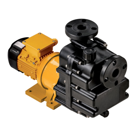
Layout and Function Assembly Fig. 2 SMP layout Terminal box Flange, pressure side Housing (consisting of 2 chambers) Filler opening Impeller (concealed) 10 Motor Flange, suction side Pump support Exhaust opening Magnetic coupling (hidden) Magnetic coupling Pumps with magnetic couplings are hermetically sealed and leaktight. -
Page 10: Transport, Storage And Disposal
Transport, Storage and Disposal Transport, Storage and Storage Disposal NOTE Material damage due to inappropriate storage! Transport Store the pump properly. The user/owner is responsible for the transport of the 1. Rinse and empty the pump if necessary. pump. 2. Seal all openings with blind plugs or plastic covers. 3. -
Page 11: Installation And Connection
Installation and connection Installation and connection Planning pipelines Note the installation example (→ 9.2 Installation example, Page 29). NOTE Water hammer may damage the pump or the system. Plan the pipes and fittings as far as possible to prevent water Material damage caused by dirt! hammer occurring. -
Page 12: Determine The Pipe Lengths And Installation Parameters
Installation and connection 5.3.4 Determine the pipe lengths and installation Make provisions for isolating and shutting off the pipes parameters For maintenance and repair work. Provide shut-off valves in the suction pipe and pressure line. Dry run protection by measuring the operating conditions Provide monitoring sensors for both pressure and flow rate, to protect the pump against dry running and consequential damage. -
Page 13: Electrical Connection
Installation and connection Electrical connection DANGER Risk of electrocution! All electrical work must be carried out only by qualified elec- tricians. Before all work on the electrical system, disconnect the motor from the mains and secure against being switched back on again. 5.5.1 Connecting the motor Follow the instructions of the motor manufacturer. -
Page 14: Operation
Operation Operation Commissioning 6.2.1 Switching on Preparing for commissioning Pump set up and connected properly Motor set up and connected properly 6.1.1 Check downtimes All connections stress-free and sealed Before starting up the pump, check the downtime and per- All safety equipment installed and tested for functionality form the following actions: Pump prepared, filled and vented correctly –... -
Page 15: Switching Off
Operation 10. If leaks are present at the housing seals or flanges, proceed Take the following measures whenever the pump is shut as follows: down: – Switch off motor. – Close the control valves. Pump is Action – Remedy the leaks. shut down Take measures appropriate for the fluid... -
Page 16: Operating The Stand-By Pump
Operation Operating the stand-by pump Stand-by pump filled and bled Suction pipe not vented Operate the stand-by pump at least once a week. 1. Fully open the suction-side fitting, if installed. 2. Open pressure-side fitting far enough so that the stand-by pump operating temperature is achieved and heating is even (→... -
Page 17: Maintenance
Maintenance and repair work should be undertaken in con- DANGER sultation with Schmitt Kreiselpumpen. The chapter describes maintenance not within the warranty period. Danger to life and material damage due to magnetic field! Maintenance during the warranty period will be performed Make sure that personnel with pacemakers do not com- by Schmitt Kreiselpumpen. -
Page 18: Check The Plain Bearings And Replace Them
Maintenance 7.2.2 Check the plain bearings and replace them Check the plain bearings and replace them When changing the plain bearings, refer to the drawings (→ 9.1.2 Drawings , Page 27). 13-1 10-1 16-1 16-2 Request spare parts from manufacturer (→... -
Page 19: Cleaning The Pump
Maintenance Dismounting Installing the pump 20. Slide the impeller (13) onto the bearing bush (14). DANGER 21. Slide the bearing bush (14) with impeller (13) onto the fixed axle in the rear cover (16). Danger to life and material damage due to magnetic field! 22. -
Page 20: Preparations For Dismounting
– Mark the precise orientation and position of all compo- nents before dismounting them. – Dismount components concentrically without canting. 3. Use only spare parts from SCHMITT. 7.3.2 Dismount the pump (E-Mail: sales@schmitt-pumpen.de). Following the drawings for disassembly (→ 9.1.2 Drawings , Page 27). -
Page 21: Installing
Maintenance Installing 7.5.1 Preparations for installation When installing please observe: Install components concentrically and without tilting in – Replace worn parts with genuine spare parts. accordance with the markings applied. – Replace seals, inserting them in such a way that they are unable to rotate. -
Page 22: Install The Pump Into The System
Maintenance 27. Install the hexagon socket screws (2). 28. Tighten the hexagon nuts with washers (12) and hexagon screws (18) crosswise. 29. Spin the motor fan impeller and make sure that the impeller (13) runs freely in the plain bearings. 7.5.3 Install the pump into the system Install the pump in the system... -
Page 23: Troubleshooting
Troubleshooting Troubleshooting DANGER Danger to life and material damage due to magnetic field! Make sure that personnel with pacemakers do not com- plete work on the pump. Secure the work place and if necessary cordon off: – Make sure that personnel with pacemakers keep a safe distance of >... - Page 24 Troubleshooting Fault number Cause Remedy – – – – – – – – Suction pipe and/or pressure line closed Open the fitting. by fitting – – – – – – – – Transport and sealing cover still in place Remove the transport and sealing cover.
- Page 25 Troubleshooting Fault number Cause Remedy – – – – – Temperature of fluid is too high: pump is Increase pump inlet pressure. cavitating Lower temperature. Contact the manufacturer. – – – – – Viscosity or specific gravity of the pumped Consult the manufacturer.
-
Page 26: Appendix
Appendix Appendix Replacement parts 9.1.1 Part numbers and designations Part no. Designation Exhaust cap Hexagon socket screw Flange (suction side) O-ring Filler cap with O-ring Housing seal Partition O-ring Filter Rear pump housing Flange (pressure side) O-ring Impeller Bearing bush O-ring Rear cover Pump support... -
Page 27: Drawings
Appendix 9.1.2 Drawings Sectional drawing 15 13 Fig. 6 Parts (sectional drawing) 11335/0320... -
Page 28: Fig. 7 Parts (Exploded Drawing)
Appendix Exploded drawing Fig. 7 Parts (exploded drawing) 11335/0320... -
Page 29: Installation Example
Appendix Installation example The following example pipe schematic shows the main compo- nents of a pump installation. Fig. 8 Installation example Shut-off valve (pressure side) Shut-off valve (ventilation) Suction pipe Pipe fixture Exhaust line 10 Strainer Foot valve or check valve Compensator 11 Tank Pressure gauge... -
Page 30: Technical Specifications
Appendix Technical specifications 9.3.5 Pump housing fill volume Further technical data (→ data sheet). SMP size ... Fill volume [l] 9.3.1 Ambient conditions Operation under any other ambient conditions should be agreed with the manufacturer. Tab. 11 Pump housing fill volume Tempera- Relative humidity [%] Installation... -
Page 31: Maintenance Schedule
Appendix Maintenance schedule The manufacture recommends shorter maintenance inter- vals if the medium being conveyed contains solid matter. The operating company should choose the maintenance intervals appropriate to the medium being conveyed. Interval Designation Action Daily Conveyed fluid Check temperature. Check discharge pressure. -
Page 32: Declaration Of Conformity
Appendix Declaration of conformity EU Declaration of Conformity Manufacturer SCHMITT-Kreiselpumpen GmbH & Co. KG Einsteinstrasse 33 D-76275 Ettlingen Type of pump Centrifugal pump Pump type SMP 130, SMP 150, SMP 170 We declare that the design of the listed pumps satisfies the provisions of the EU Directives.
Need help?
Do you have a question about the SMP Series and is the answer not in the manual?
Questions and answers