
Related Manuals for Profimess SW-07 Series


Summary of Contents for Profimess SW-07 Series
- Page 1 Profimess GmbH Twischlehe 5 D-27580 Bremerhaven Operating instructions SW-07 (1/2“) Varible Area Flowmeter and Switch Status: February 2015 Technical modifications reserved...
- Page 2 Profimess GmbH Twischlehe 5 27570 Bremerhaven Germany Telephone: +49 471 98 24 - 151 Fax: +49 471 98 24 - 152 email: info@profimess.de Internet: www.profimess.com 20.02.2015...
- Page 3 – even in part – as well as dissemina- tion and/or communication of their con- tent is forbidden without prior written authorization from PROFIMESS Limitations of liability ("manufacturer"). Violations All details and instructions in this...
-
Page 4: Table Of Contents
Table of contents Table of contents Overview...................... 7 1.1 Short description.................. 7 1.2 Warranty and guarantee provisions............. 7 1.3 Customer service................. 7 Safety......................8 2.1 Explanation of symbols................ 8 2.2 Correct use in accordance with these instructions......10 2.3 Special precautions................11 2.3.1 Hazards from electrical current............ - Page 5 Table of contents 5.2 Requirements at the place of installation........... 25 5.3 reparatory work.................. 26 5.4 Installation in the pipe system............29 5.5 Initial startup..................33 5.6 Electrical connection................34 5.6.1 Plug connector DIN 43650.............. 35 5.6.2 Plug connector M12x1..............36 5.6.3 Cable....................
- Page 6 Table of contents 9.3 Return Materials................. 68 9.3.1 Return Materials Authorization............68 9.4 Disposal..................... 69 Technical data................... 70 10.1 Device data plate................70 10.2 Switch contact data plate..............70 10.3 Dimension sheet................71 10.4 General specifications..............72 10.5 Electrical specifications..............72 10.6 Measuring ranges................
-
Page 7: Overview
Overview Customer service Overview 1.1 Short description External measuring devices can be connected at the socket. 1.2 Warranty and guar- antee provisions Warranty and guarantee provisions are contained in the general terms and conditions of the manufacturer. 1.3 Customer service For technical information, please con- tact our customer service department (for contact details, see Page 2). -
Page 8: Safety
Safety Explanation of symbols Safety 2.1 Explanation of sym- This chapter provides an overview of important safety aspects required for bols optimum protection of personnel as Safety instructions well as for safe installation and safe operation of the device. Safety instructions in this manual are marked by symbols. - Page 9 Safety Explanation of symbols Designates step-by-step han- dling instructions CAUTION! ð Designates a state or an This combination of symbol and automatic sequence as a signal word indicates a possibly result of a specific operating dangerous situation that might step result in minor or slight injuries if it is not avoided.
-
Page 10: Correct Use In Accordance With These Instructions
Safety Correct use in accordance with these instructions 2.2 Correct use in accordance with WARNING! these instructions Danger due to incorrect use! The device is designed and con- – Use the flow monitor only structed exclusively for the intended within the stipulated perform- use described herein. -
Page 11: Special Precautions
Safety Special precautions > Hazards from electrical current 2.3.1 Hazards from elec- trical current All claims for damages due to incorrect Electrical current use are excluded. DANGER! 2.3 Special precautions Danger to life from electrical The following section lists residual current! risks that might arise from the device. -
Page 12: Mechanical Hazards
Safety Special precautions > Mechanical hazards – Never bridge fuses or put CAUTION! them out of operation. Always observe the correct current Risk of injury on sharp edges ratings when replacing fuses and pointed corners! – Keep moisture away from live Sharp edges and pointed corners parts. -
Page 13: Hazards From High Or Low Temperatures
Safety Special precautions > Radiation hazards 2.3.3 Hazards from high 2.3.4 Radiation hazards or low temperatures Strong magnetic fields Hot or cold surfaces WARNING! WARNING! Danger to life from strong mag- netic fields! Risk of injury from hot or cold surfaces! Strong magnetic fields may cause severe injuries or even be fatal, as... -
Page 14: Hazards Caused By Media
Safety Personnel requirements 2.4 Personnel require- – Do not place any electronic ments storage media, credit cards, etc. within the vicinity of the magnetic source. Data could WARNING! be deleted Risk of injury due to use of insufficiently trained and quali- fied personnel! 2.3.5 Hazards caused by If unqualified personnel work on... -
Page 15: Personal Safety Equipment
Safety Personal safety equipment The following lists the personnel quali- When performing the various tasks at, fications for the various areas of and with the device, personnel must activity: wear personal safety equipment. Spe- cial reference is made of this in the Qualified electrician individual chapters within these Oper- Due to specialized training, knowledge... -
Page 16: Protective Systems
Safety Spare parts 2.6 Protective systems Protective gloves protect the hands from friction, burns, grazing, abrasion, Integration within an emergency- surface cuts or deeper injuries, as well stop concept is required as from direct contact with hot or cold surfaces. The device is designed for use as a part of a machine or system. -
Page 17: Environmental Protection
Safety Responsibility of the owner Always purchase spare parts from an Cleaning fluids authorized dealer or directly from the Solvent-based cleaning fluids contain manufacturer (For contact details, see toxic substances. They must never be Page 2). released into the environment and The spare parts list is in the annex. - Page 18 Safety Responsibility of the owner In addition to the safety instructions The owner must clearly regulate contained in these Operating Instruc- and determine responsibilities for tions, the safety, accident prevention installation, operation, trouble- and environmental protection regula- shooting, maintenance and tions applicable to the field of applica- cleaning.
- Page 19 Safety Responsibility of the owner The owner must ensure that the maintenance intervals described in these Operating Instructions are adhered to at all times. The owner must ensure that the device is completely free of any residual media before disposal. Remains of corrosive or toxic materials must be neutralized.
-
Page 20: Design And Function
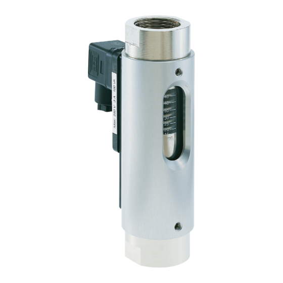
Design and function Device description Design and function 3.1 Overview 3.2 Device description SW-07 flow meters work according to the functional principle of the variable area flowmeter. The flow monitor is installed into a pipe system and meas- ures the flow-rate of the medium flowing through the pipe system. -
Page 21: Component Description
Design and function Component description 3.3 Component descrip- Sight glass tion Switch contact Fig. 4: Sight glass A measuring scale is burnt onto the sight glass, from which the current rate Fig. 3: Switch contact and female of flow can be read-off. socket A potential-free Reed-contact is cast into the switch contact housing... -
Page 22: Transport, Packaging And Storage
Transport, packaging and storage Packaging Transport, packaging and storage 4.1 Safety instructions 4.2 Transport inspec- for transport tion On delivery, make an immediate check for completeness and check for trans- port damages. Improper transport If there are any visible external trans- port damages then proceed as follows: NOTICE! Do not accept the delivery... -
Page 23: Symbols On The Shipping Box
Transport, packaging and storage Storage Handling packaging materials Fragile Dispose of packaging material in accordance with the valid legal regula- tions and local ordinances. NOTICE! Designates packages with breakable Danger to the environment due or damageable contents. to incorrect disposal! Handle the package carefully and do Packaging is made of valuable raw not allow it to fall or be subjected to jar-... - Page 24 Transport, packaging and storage Storage Storage instructions in addition to the instructions listed here may be listed on the packages. Follow these instructions also. 20.02.2015...
-
Page 25: Installation And Initial Startup Operation
Installation and initial startup operation Requirements at the place of installation Installation and initial startup opera- tion 5.1 Safety Safeguard against restart Incorrect installation and initial startup WARNING! Danger to life due to unauthor- ized restart! WARNING! There is a risk of severe or even Risk of injury due to incorrect fatal injuries from unauthorized installation and initial startup! -
Page 26: Reparatory Work
Installation and initial startup operation reparatory work The flow monitor must be installed in such a way as to preclude WARNING! damage by outside force. It must be ensured that the flow monitor Danger due to incorrect installa- cannot be damaged. If necessary, tion! install an appropriate impact pro- If the criteria listed above are not... - Page 27 Installation and initial startup operation reparatory work Only install the flow monitor in one of the positions displayed in the drawing. The medium must flow in the direction of the arrow (from a low to a high scale value). Unimpeded flow sections NOTICE! Measuring inaccuracy due to incorrect installation!
- Page 28 Installation and initial startup operation reparatory work Unimpeded outlet Strainer Fig. 7: Unimpeded outlet If the pipe system ends at an unim- peded outlet, the flow monitor must not be installed directly in front of the opening. The device must always be completely filled with media to ensure measuring accuracy.
-
Page 29: Installation In The Pipe System
Installation and initial startup operation Installation in the pipe system 5.4 Installation in the Prepare the device pipe system NOTICE! WARNING! Risk of damage to property due to contamination! Risk of injury from pressurized Contamination and deposits may lines! impair the free movement of the If the pipe system is under pres- float, thereby damaging the sure when installing the device,... - Page 30 Installation and initial startup operation Installation in the pipe system WARNING! WARNING! Risk of injury from hot or cold Risk of injury from media in the surfaces! pipe system! Pipelines can heat up/cool down If the pipe system contains toxic or dramatically due to the media other hazardous media, severe flowing through them.
- Page 31 Installation and initial startup operation Installation in the pipe system Sealing the pipe connection Personnel: Qualified personnel A suitable sealant must be selected, depending on the condi- Nap the thread. tion/composition of the pipe lines, the medium and the operating and environmental conditions.
- Page 32 Installation and initial startup operation Installation in the pipe system Apply sealing strip (Fig. 9/1) to Install device in pipe system the napped thread in the thread- Personnel: direction. Observe the quantity Qualified personnel recommended by the sealant manufacturer Protective equipment: Protective gloves Tool: Fixed spanner...
-
Page 33: Initial Startup
Installation and initial startup operation Initial startup 5.5 Initial startup The following steps must be carried out before initial startup and any subse- quent startup (e.g. after removal and installation during maintenance). WARNING! Make sure that the plant is operating vibration-free. Vibrations could destroy the Fig. -
Page 34: Electrical Connection
Installation and initial startup operation Electrical connection 5.6 Electrical connec- tion NOTICE! The electrical connection of the flow Vent the pipe line. If there monitor is accomplished through the are air bubbles in the line connector plug or the cast on power during the measurement cable leading from the switch housing. -
Page 35: Plug Connector Din 43650
Installation and initial startup operation Electrical connection > Plug connector DIN 43650 – Secure against switching back on – Check for absence of voltage – Ground and short – Cover or cordon off other live parts in the vicinity – Never bridge fuses or put them out of operation. -
Page 36: Plug Connector M12X1
Installation and initial startup operation Electrical connection > Plug connector M12x1 Fig. 16: Pin assignment, plug socket, change-over contact. The ground-pin is not used. 5.6.2 Plug connector M12x1 Wiring diagram, connector M12x1 Fig. 17: Pin assignment, connector M12x1 (Form 15x50) Wiring diagram Normally open: Fig. -
Page 37: Cable
Installation and initial startup operation Grounding the device 5.6.4 Degree of protection (IP-Code) The specified degree of protection (IP) is only ensured if approved connection material is used (see following table). Fig. 19: Switch position under no-flow Device Specifi- Degree of condition connec- cation... -
Page 38: Plug Connection
Installation and initial startup operation Plug connection 5.8 Plug connection Personnel: Qualified electrician Tool: Flat-bladed screwdriver Fig. 21: Remove socket Remove the socket (Fig. 21/02). Fig. 20: Detach socket Release the fixing screw (Fig. 20/01) from the socket. 20.02.2015... - Page 39 Installation and initial startup operation Plug connection Fig. 23: Disconnect the screw connec- tion Unscrew the screw connection (Fig. 23/01) by turning in the left direction Fig. 22: Disconnect inner section Guide the connecting wire through the screw connection in Remove the inner section from the socket the socket.
- Page 40 Installation and initial startup operation Plug connection Retighten the screw connection Plug the socket onto the con- (Fig. 23/01) by turning it to the nector plug and tighten the fixing right screw (Fig. 20/01) Fig. 24: Pin assignment, plug socket, normally-open contact (Form 15x50) 20.02.2015...
-
Page 41: Contact Protection Measures
Installation and initial startup operation Contact protection measures Inductive load There is danger of voltage peaks from inductive loads when switching off (up to 10 times the rated voltage). Induc- tive loads are caused by, e.g.: Contactors, relays Solenoid valves Electric motors Examples of protective measures: Fig. - Page 42 Installation and initial startup operation Contact protection measures Protection against ohmic loads can be achieved through installation of a resistor in the circuit, or by heating the glow filament. For connection to high- impedance consumers (ex. PLC), a protective circuit is not needed. Fig.
-
Page 43: Operation
Operation Setting the switch point Operation 6.1 Setting the switch point Setting the switch point of an installed device The following instructions describe the procedure for a Normally Open Contact (NOC). The actual state (open or closed), can be deter- mined using a continuity meter. - Page 44 Operation Setting the switch point Re-tighten the switch contact Setting the switch point of a non- fixing screw (Fig. 31) using a installed device hex screwdriver. When doing so, observe the correct tightening torque of the screw. Ä Chapter 11.1 “Tightening torque”...
-
Page 45: Checking The Flow
Operation Checking the flow 6.2 Checking the flow Condition 2: The contact is open Slowly push the switch contact Reading-off the flow value in the direction of flow until the Personnel: contact closes. Then keep Qualified personnel pushing slowly in the direction of flow until the contact opens. - Page 46 Operation Checking the flow To obtain greatest reading accu- racy, read-off at eye level. (Fig. 33, middle arrow). The read-off value can be falsified by viewing at an angle Read-off the flow value from the measuring scale 20.02.2015...
-
Page 47: Troubleshooting
Troubleshooting Safety Troubleshooting 7.1 Safety This chapter describes possible mal- functions of the device, their causes Work carried out incorrectly to and repair. remedy a malfunction If malfunctions persist or increase, shorten the maintenance interval to meet the actual operating conditions. WARNING! For malfunctions not described in this Risk of injury due to incorrect... - Page 48 Troubleshooting Safety Conduct in case of malfunction The complete machine or system may be unsafe if there is a defect at the flow monitor (e.g. broken sight glass). The following always applies: In case of malfunctions that present an immediate danger to persons or valuables, proceed according to the valid emer- gency plans for the system...
-
Page 49: Troubleshooting Guide
Troubleshooting Troubleshooting guide 7.2 Troubleshooting guide Fault description Cause Remedy Personnel The switch contact No medium Check that medium is Qualified does not switch. flowing through flowing through the pipe- personnel flow monitor line Flow is too low or Adjust the switch Qualified the switch con- contact to a lower... - Page 50 Troubleshooting Troubleshooting guide Fault description Cause Remedy Personnel Float is stuck Disassemble and clean Qualified the device personnel Switch contact is Remedy the cause of Qualified defective the defect (short-cir- personnel cuit, overload) Replace the switch contact The switch point is Improper scale Request proper conver- Qualified...
-
Page 51: Maintenance
Maintenance Maintenance plan Maintenance 8.1 Safety 8.2 Maintenance plan Maintenance work performed incor- Intervals for replacing wear parts rectly SW-07 type flow monitors require very little maintenance due to the small number of moving parts. The intervals WARNING! for the replacement of wear parts depend significantly on the operating Risk of injury due to mainte- conditions as well as on the composi-... -
Page 52: Removal From The Pipe System
Maintenance Removal from the pipe system Interval Maintenance work Personnel Visual inspection for dirt/soiling Qualified personnel Visual inspection for free movement of float Qualified personnel Visual inspection for leaks from the device Qualified personnel Check function of switch contact Qualified personnel 8.3 Removal from the pipe system WARNING! -
Page 53: Disassembly
Maintenance Disassembly Removing the device from the pipe system WARNING! Personnel: Risk of injury from media in the Qualified personnel pipe system! Protective equipment: If the pipe system contains toxic or hazardous media, severe injuries With hazardous media, the protec- may be caused by escaping tive equipment specified in the media! - Page 54 Maintenance Disassembly Protective equipment: With hazardous media, the protec- WARNING! tive equipment specified in the Risk of injury due to incorrect Safety Data Sheet of the medium disassembly! must be worn. In addition, the specifications of the system oper- – The device may still contain ator must be followed.
- Page 55 Maintenance Disassembly Fig. 34: Loosen screws Fig. 35: Remove the process connec- tion (outlet) Loosen the top 3 hex socket screws (Fig. 34/01) using a hex screwdriver. CAUTION! Carefully pull the process connection outlet from the device housing, turning slightly when doing so (Fig.
- Page 56 Maintenance Disassembly Fig. 36: Loosen screws Fig. 37: Remove the inner section Secure the device with one hand Carefully remove the inner sec- to ensure the sight glass does tion (Fig. 37/01) of the device not slip out. With the other hand, (sight glass, spring and float with loosen the lower 3 hex head magnets) as a unit together with...
-
Page 57: Maintenance
Maintenance Maintenance > Cleaning 8.5 Maintenance 8.5.1 Cleaning It is the responsibility of the operator to establish appropriate intervals and pro- cedures for cleaning the individual parts of the device. It must be ensured that the parts are not damaged during the cleaning process. -
Page 58: Parts Replacement
Maintenance Maintenance > Assembly Protective equipment: With hazardous media, the protec- CAUTION! tive equipment specified in the Risk of injury due to damaged Safety Data Sheet of the medium parts! must be worn. In addition, the specifications of the system oper- If parts of the device are broken or ator must be followed. - Page 59 Maintenance Maintenance > Assembly Personnel: Qualified personnel Tool: Hex screwdriver Torque screwdriver and assorted blades Special tools: Test rod Magnetic pole indicator Fig. 40: O-ring (Glass buffer) Carefully install the O-ring (Glass buffer) onto the process connection (Fig. 40/01), so that it is properly seated on the lower portion of the process connec- tion (Fig.
- Page 60 Maintenance Maintenance > Assembly Insert the spring (Fig. 42/01) and magnets (Fig. 42/02) into the float (Fig. 42/03), observing the magnetic polarity (north pole toward the outlet side). Lubricate the process connec- tion O-rings lightly. A list of suitable lubricants is contained in the annex Ä...
- Page 61 Maintenance Maintenance > Assembly CAUTION! Insert the process connec- tion(inlet) (Fig. 43/01) care- fully into the sight glass, twisting lightly. The sight glass can break if too much force is exerted or if the process connection is canted. Fig. 45: Insert the process connection into the device housing Insert the process connection (inlet) and sight glass into the...
- Page 62 Maintenance Maintenance > Assembly Fig. 46: Secure the process connection Fig. 47: Align the sight glass (inlet) Align the sight glass scale to the Secure the inlet process connec- sight window of the device tion to the device housing with 3 housing.
- Page 63 Maintenance Maintenance > Assembly Fig. 48: Insert float and inner parts Fig. 49: Position process connection (outlet) in device housing Insert the float, magnets and spring into the device housing. Insert the process connection (outlet) into the device housing. Insert the process connection (outlet) (Fig.
- Page 64 Maintenance Maintenance > Assembly Fig. 50: Tighten hex socket screws Fig. 51: Check for ease of movement Tighten the 3 hex head screws Check the float for ease of (Fig. 50/01), observing the movement by applying pressure proper torque ( Ä...
-
Page 65: Switch Contact Replacement
Maintenance Maintenance > Switch contact replacement 8.5.4 Switch contact replacement Tool: Flat-bladed screwdriver Hex screwdriver Fig. 53: Remove the female socket Remove the female socket and gasket (Fig. 53/02) by pulling upwards. Fig. 52: Loosen female socket Loosen the fixing screw of the female socket (Fig. - Page 66 Maintenance Maintenance > Switch contact replacement Fig. 54: Loosen set screw Fig. 55: Remove switch housing Using a hex screwdriver Remove the switch contact from (Fig. 54/01) remove the set the guide surface (Fig. 55). screw of the switch contact Attach the new switch contact The guide groove of the switch contact must be slipped over the...
-
Page 67: Measures To Be Taken After Maintenance Work
Maintenance Measures to be taken after maintenance work Position the female socket and gasket, then tighten the fixing screw. 8.6 Measures to be taken after mainte- nance work Take the following steps after comple- tion of maintenance work and before switching on the device: Check all previously loosened/ released screw connections for... -
Page 68: Disassembly And Disposal
– In case of doubt, contact the Profimess will apply. Return shipments manufacturer which do not comply with the returns policy may be refused by Profimess at the expense of the consignor. 20.02.2015... -
Page 69: Disposal
Disassembly and disposal Disposal 9.4 Disposal If no return or disposal agreement has been made then recycle disassembled components: Scrap metals Recycle plastic elements Dispose of the remaining compo- nents according to their material properties NOTICE! Danger to the environment due to incorrect disposal! Potential risk to the environment may arise due to incorrect dis-... -
Page 70: Technical Data
Technical data Switch contact data plate Technical data 10.1 Device data plate The data plate is on the mechanical part of the flow monitor/flow meter and contains the following information: 1. Ordering number 2. Operating range 3. Process connection 4. Serial number 5. -
Page 71: Dimension Sheet
Technical data Dimension sheet 10.3 Dimension sheet 20.02.2015... -
Page 72: General Specifications
Technical data Electrical specifications 10.4 General specifications Type Overall dimensions (mm) SW-07 SW-07 SW-07 SW-07 Type Overall dimensions (mm) weight SW-07 SW-07 SW-07 SW-07 * NPT threads on request ** Sealed in cable weight, 2m approx 80g 10.5 Electrical specifications Change-Over Contact (COC) Data Value Unit... - Page 73 Technical data Electrical specifications Normally Open Contact (NOC) Data Value Unit Voltage 230 V Current, maximum Power, maximum 60 VA Change-Over Contact (COC) M12x1 (-20 °C–85 °C) Data Value Unit Voltage 125 V Current, maximum 1,5 A Power, maximum 50 VA Minimum load 3 VA Normally Open Contact (NOC) M12x1 (-20 °C–85 °C)
-
Page 74: Measuring Ranges
Technical data Operating data 10.6 Measuring ranges 10.6.1 Standard measuring ranges Type Switch range for oil, density 0,9 kg/1 dm at 20 °C* l/min SW-07.2.X.1.03. 0,5 – 1,7 8,0 – 27,0 SW-07.2.X.1.03a. 0,8 – 2,5 13,0 – 40,0 SW-07.2.X.1.04. 1,3 – 4,0 21,0 –... -
Page 75: Appendix
Appendix Replacement parts Appendix 11.1 Tightening torque Component/ Description Size Torque Number function Device Hexagon M4x5 1,4 Nm housing screw socket screw Switch contact Cylinder head M3x10 0,4 Nm housing screw assembly screw 11.2 Replacement parts The following replacement parts drawing provides an example of the construction of a SW-07 type flow monitor. - Page 76 Appendix Replacement parts Item Nr. of Description pieces process connection (inlet) O-Ring (glass buffer) O-Ring (seal) sight glass device housing hex socket screw float magnet spring process connection (outlet) Cylinder pin (switch contact) switch contact with male connector female socket and gasket fixing screw (female socket) fixing screw, hex 20.02.2015...
-
Page 77: Tools
Appendix Sealant 11.3 Tools The following tools are required: Tool Fixed spanner 27 mm Flat-bladed screwdriver, blade width 5,5 mm Hex screwdriver 2 mm Hex screwdriver 2,5 mm Torque screwdriver, and corre- sponding blades Special tool Test rod Magnetic pole tester 11.4 Sealant Before using a sealant, ensure that... -
Page 78: Lubricants
Appendix Lubricants 11.5 Lubricants Before using a lubricant, always make sure that it is compatible with the oper- ating medium. For the proper mounting of O-rings, an O-ring installation tool may be purchased from the manufacturer. The following lubricants are suitable to facilitate installing the O-rings: Lubricant O-ring material EPDM... - Page 79 Profimess GmbH Twischlehe 5 D-27580 Bremerhaven Operating instructions SW-07 (1“) Varible Area Flowmeter and Switch Status: February 2015 Technical modifications reserved...
- Page 80 Profimess GmbH Twischlehe 5 27570 Bremerhaven Germany Telephone: +49 471 98 24 - 151 Fax: +49 471 98 24 - 152 email: info@profimess.de Internet: www.profimess.com 20.02.2015...
- Page 81 – even in part – as well as dissemina- tion and/or communication of their con- tent is forbidden without prior written authorization from PROFIMESS Limitations of liability ("manufacturer"). Violations All details and instructions in this...
- Page 82 Table of contents Table of contents Overview...................... 7 1.1 Overview....................7 1.2 Warranty and guarantee provisions............. 7 1.3 Customer service................. 7 Safety......................8 2.1 Explanation of symbols................ 8 2.2 Correct use in accordance with these instructions......10 2.3 Special precautions................11 2.3.1 Hazards from electrical current............
- Page 83 Table of contents 5.2 Requirements at the place of installation........... 25 5.3 Preparatory work................26 5.4 Installation in the pipe system............29 5.5 Initial startup..................33 5.6 Electrical connection................34 5.6.1 Connector DIN 43650..............35 5.6.2 Plug connector M12x1..............36 5.6.3 Cable....................
- Page 84 Table of contents 9.3 Disposal..................... 69 9.4 Return Materials................. 70 9.4.1 Return Materials Authorization............70 Technical data................... 71 10.1 Device data plate................71 10.2 Switch contact data plate..............71 10.3 Dimension sheet................72 10.4 General specifications..............73 10.5 Electrical specifications..............77 10.6 Measuring ranges................
-
Page 85: Overview
Overview Customer service Overview 1.1 Overview 1.2 Warranty and guar- antee provisions Warranty and guarantee provisions are contained in the general terms and conditions of the manufacturer. 1.3 Customer service For technical information, please con- tact our customer service department (for contact details, see Page 2). -
Page 86: Safety
Safety Explanation of symbols Safety 2.1 Explanation of sym- This chapter provides an overview of important safety aspects required for bols optimum protection of personnel as Safety instructions well as for safe installation and safe operation of the device. Safety instructions in this manual are marked by symbols. - Page 87 Safety Explanation of symbols Designates step-by-step han- dling instructions CAUTION! ð Designates a state or an This combination of symbol and automatic sequence as a signal word indicates a possibly result of a specific operating dangerous situation that might step result in minor or slight injuries if it is not avoided.
-
Page 88: Correct Use In Accordance With These Instructions
Safety Correct use in accordance with these instructions 2.2 Correct use in accordance with WARNING! these instructions Danger due to incorrect use! The device is designed and con- Incorrect use of the flow monitor structed exclusively for the intended may result in dangerous situations use described herein. -
Page 89: Special Precautions
Safety Special precautions > Hazards from electrical current 2.3.1 Hazards from elec- All claims for damages due to incorrect use are excluded. trical current Electrical current 2.3 Special precautions The following section lists residual DANGER! risks that might arise from the device. Danger to life from electrical To reduce health risks and prevent current! -
Page 90: Mechanical Hazards
Safety Special precautions > Mechanical hazards – Never bridge fuses or put CAUTION! them out of operation. Always observe the correct current Risk of injury on sharp edges ratings when replacing fuses and pointed corners! – Keep moisture away from live Sharp edges and pointed corners parts. -
Page 91: Hazards From High Or Low Temperatures
Safety Special precautions > Radiation hazards 2.3.3 Hazards from high 2.3.4 Radiation hazards or low temperatures Strong magnetic fields Hot or cold surfaces WARNING! WARNING! Danger to life from strong mag- netic fields! Risk of injury from hot or cold surfaces! Strong magnetic fields may cause severe injuries or even be fatal, as... -
Page 92: Hazards Caused By Media
Safety Personnel requirements 2.4 Personnel require- – Do not place any electronic ments storage media, credit cards, etc. within the vicinity of the magnetic source. Data could WARNING! be deleted Risk of injury due to use of insufficiently trained and quali- fied personnel! 2.3.5 Hazards caused by If unqualified personnel work on... -
Page 93: Personal Safety Equipment
Safety Personal safety equipment The following lists the personnel quali- When performing the various tasks at, fications for the various areas of and with the device, personnel must activity: wear personal safety equipment. Spe- cial reference is made of this in the Qualified electrician individual chapters within these Oper- Due to specialized training, knowledge... -
Page 94: Protective Systems
Safety Spare parts 2.6 Protective systems Protective gloves protect the hands from friction, burns, grazing, abrasion, Integration within an emergency- surface cuts or deeper injuries, as well stop concept is required as from direct contact with hot or cold surfaces. The device is designed for use as a part of a machine or system. -
Page 95: Environmental Protection
Safety Responsibility of the owner Always purchase spare parts from an Cleaning fluids authorized dealer or directly from the Solvent-based cleaning fluids contain manufacturer (For contact details, see toxic substances. They must never be Page 2). released into the environment and The spare parts list is in the annex. - Page 96 Safety Responsibility of the owner In addition to the safety instructions The owner must clearly regulate contained in these Operating Instruc- and determine responsibilities for tions, the safety, accident prevention installation, operation, trouble- and environmental protection regula- shooting, maintenance and tions applicable to the field of applica- cleaning.
- Page 97 Safety Responsibility of the owner The owner must ensure that the maintenance intervals described in these Operating Instructions are adhered to at all times. The owner must ensure that the device is completely free of any residual media before disposal. Remains of corrosive or toxic materials must be neutralized.
-
Page 98: Design And Function
Design and function Device description Design and function 3.1 Overview addition to electrical control through the Reed-contact (switch contact), the current flow rate can also be read-off on the measuring scale on the sight glass. SW-07 flow monitors are used in, e.g. lubricating circuits: The flow monitor monitors the volumetric flow of the lubricating media to ensure it is high... -
Page 99: Component Description
Design and function Component description 3.3 Component descrip- Sight glass tion Switch contact Fig. 4: Sight glass A measuring scale is burnt onto the sight glass, from which the current rate Fig. 3: Switch contact and female of flow can be read-off. socket A potential-free Reed-contact is cast into the switch contact housing... -
Page 100: Transport, Packaging And Storage
Transport, packaging and storage Packaging Transport, packaging and storage 4.1 Safety instructions 4.2 Transport inspec- for transport tion On delivery, make an immediate check for completeness and check for trans- port damages. Improper transport If there are any visible external trans- port damages then proceed as follows: NOTICE! Do not accept the delivery... -
Page 101: Symbols On The Shipping Box
Transport, packaging and storage Storage Handling packaging materials Fragile Dispose of packaging material in accordance with the valid legal regula- tions and local ordinances. NOTICE! Designates packages with breakable Danger to the environment due or damageable contents. to incorrect disposal! Handle the package carefully and do Packaging is made of valuable raw not allow it to fall or be subjected to jar-... - Page 102 Transport, packaging and storage Storage Storage instructions in addition to the instructions listed here may be listed on the packages. Follow these instructions also. 20.02.2015...
-
Page 103: Installation And Initial Startup
Installation and initial startup Requirements at the place of installation Installation and initial startup 5.1 Safety Safeguard against restart Incorrect installation and initial startup WARNING! Danger to life due to unauthor- ized restart! WARNING! There is a risk of severe or even Risk of injury due to incorrect fatal injuries from unauthorized installation and initial startup! -
Page 104: Preparatory Work
Installation and initial startup Preparatory work The flow monitor must be installed in such a way as to preclude WARNING! damage by outside force. It must be ensured that the flow monitor Danger due to incorrect installa- cannot be damaged. If necessary, tion! install an appropriate impact pro- If the criteria listed above are not... - Page 105 Installation and initial startup Preparatory work Only install the flow monitor in one of the positions displayed in the drawing. The medium must flow in the direction of the arrow (from a low to a high scale value). Unimpeded flow sections NOTICE! Measuring inaccuracy due to incorrect installation!
- Page 106 Installation and initial startup Preparatory work Unimpeded outlet Strainer Fig. 7: Unimpeded outlet If the pipe system ends at an unim- peded outlet, the flow monitor must not be installed directly in front of the opening. The device must always be completely filled with media to ensure measuring accuracy.
-
Page 107: Installation In The Pipe System
Installation and initial startup Installation in the pipe system 5.4 Installation in the Prepare the device pipe system NOTICE! WARNING! Risk of damage to property due to contamination! Risk of injury from pressurized Contamination and deposits may lines! impair the free movement of the If the pipe system is under pres- float, thereby damaging the sure when installing the device,... - Page 108 Installation and initial startup Installation in the pipe system WARNING! WARNING! Risk of injury from hot or cold Risk of injury from media in the surfaces! pipe system Pipelines can heat up/cool down If the pipe system contains toxic or dramatically due to the media other hazardous media, severe flowing through them.
- Page 109 Installation and initial startup Installation in the pipe system Sealing the pipe connection Personnel: Qualified personnel A suitable sealant must be selected, depending on the condi- Nap the thread. tion/composition of the pipe lines, the medium and the operating and environmental conditions.
- Page 110 Installation and initial startup Installation in the pipe system Apply sealing strip (Fig. 9/1) to Install device in pipe system the napped thread in the thread Personnel: direction. Observe the quantity Qualified personnel recommended by the sealant manufacturer Protective equipment: Protective gloves Tool: Fixed spanner...
-
Page 111: Initial Startup
Installation and initial startup Initial startup 5.5 Initial startup The following steps must be carried out before initial startup and any subse- quent startup (e.g. after removal and installation during maintenance). WARNING! Make sure that the plant is operating vibration-free. Vibrations could destroy the Fig. -
Page 112: Electrical Connection
Installation and initial startup Electrical connection 5.6 Electrical connec- tion NOTICE! The electrical connection of the flow Vent the pipe line. If there monitor is accomplished through the are air bubbles in the line connector plug or the cast on power during the measurement cable leading from the switch housing. -
Page 113: Connector Din 43650
Installation and initial startup Electrical connection > Connector DIN 43650 5.6.1 Connector DIN – Secure against switching 43650 back on – Check for absence of Wiring diagram of the supplied voltage socket (DIN 43650, Form A) (Front view). – Ground and short –... -
Page 114: Plug Connector M12X1
Installation and initial startup Electrical connection > Plug connector M12x1 5.6.2 Plug connector M12x1 Wiring diagram, socket (M12x1) Fig. 15: Switch position under no-flow condition Fig. 17: Pin-assignment, socket M12x1 Form 30x70) Fig. 16: Pin assignment, plug socket, change-over contact. The ground-pin is Wiring diagram not used. -
Page 115: Cable
Installation and initial startup Grounding the device 5.6.4 Degree of protection (IP-Code) The specified degree of protection (IP) is only ensured if approved connection material is used (see following table). Fig. 19: Switch position under no-flow Device Specifi- Degree of condition connec- cation... -
Page 116: Plug Connection
Installation and initial startup Plug connection 5.8 Plug connection Personnel: Qualified electrician Tool: Flat-bladed screwdriver Fig. 21: Remove socket Remove socket (Fig. 21/1). Fig. 20: Detach socket Release the fixing screw (Fig. 20/1) from the socket. 20.02.2015... - Page 117 Installation and initial startup Plug connection Fig. 22: Disconnect inner section Remove the inner section from Fig. 23: Disconnect the screw connec- the socket. To do this, place a tion flat-bladed screwdriver into the slot (Fig. 22/1) and carefully pry Unscrew the screw connection out the inner section.
-
Page 118: Contact Protection Measures
Installation and initial startup Contact protection measures Plug the socket onto the connec- tion plug and tighten the fixing screw. (Fig. 20/1) Fig. 25: Pin assignment, plug socket, change-over contact (Form 30x70) 5.9 Contact protection Fig. 24: Pin assignment, plug socket, measures normally-open contact (Form 30x70) The Reed-switches used in the switch... - Page 119 Installation and initial startup Contact protection measures Inductive load There is danger of voltage peaks from inductive loads when switching off (up to 10 times the rated voltage). Induc- tive loads are caused by, e.g.: Contactors, relays Fig. 28: Protective measure against capacitive loads Solenoid valves Electric motors...
- Page 120 Installation and initial startup Contact protection measures Protection against ohmic loads can be achieved through installation of a resistor in the circuit, or by heating the glow filament. For connection to high- impedance consumers (ex. PLC), a protective circuit is not needed. 20.02.2015...
-
Page 121: Operation
Operation Setting the switch point Operation 6.1 Setting the switch Personnel: point Qualified personnel Tool: Flat-bladed screwdriver Setting the switch point of an Adjust the flow to be monitored installed device and read it off at the scale on the device. - Page 122 Operation Setting the switch point Condition 1: The contact is now Setting the switch point of a non- closed installed device Slowly push the switch contact in the direction of flow until the contact opens Condition 1: The contact is now open Slowly push the switch contact in the direction of flow until the...
-
Page 123: Checking The Flow
Operation Checking the flow 6.2 Checking the flow Condition 1: The contact is now closed Reading-off the flow value Slowly push the switch contact Personnel: in the direction of flow until the Qualified personnel contact opens Protective equipment: Condition 2: The contact is now open Goggles Slowly push the switch contact... - Page 124 Operation Checking the flow To obtain greatest reading accu- racy, read-off at eye level. (Fig. 33, middle arrow). The read-off value can be falsified by viewing at an angle Read-off the flow value from the measuring scale 20.02.2015...
-
Page 125: Troubleshooting
Troubleshooting Safety Troubleshooting 7.1 Safety This chapter describes possible mal- functions of the device, their causes Work carried out incorrectly to and repair. remedy a malfunction If malfunctions persist or increase, shorten the maintenance interval to meet the actual operating conditions. WARNING! For malfunctions not described in this Risk of injury due to incorrect... - Page 126 Troubleshooting Safety Conduct in case of malfunction The complete machine or system may be unsafe if there is a defect at the flow monitor (e.g. broken sight glass). The following always applies: In case of malfunctions that present an immediate danger to persons or valuables, proceed according to the valid emer- gency plans for the system...
-
Page 127: Troubleshooting Guide
Troubleshooting Troubleshooting guide 7.2 Troubleshooting guide Fault description Cause Remedy Personnel The switch contact No medium Check that medium is Qualified does not switch. flowing through flowing through the pipe- personnel flow monitor line Flow is too low or Adjust the switch Qualified the switch con- contact to a lower... - Page 128 Troubleshooting Troubleshooting guide Fault description Cause Remedy Personnel Float is stuck Disassemble and clean Qualified the device personnel Switch contact is Remedy the cause of Qualified defective the defect (short-cir- personnel cuit, overload) Replace the switch contact The switch point is Improper scale Request proper conver- Qualified...
-
Page 129: Maintenance
Maintenance Maintenance plan Maintenance 8.1 Safety 8.2 Maintenance plan Maintenance work performed incor- Intervals for replacing wear parts rectly SW-07 type flow monitors require very little maintenance due to the small number of moving parts. The intervals WARNING! for the replacement of wear parts depend significantly on the operating Risk of injury due to mainte- conditions as well as on the composi-... -
Page 130: Removal From The Pipe System
Maintenance Removal from the pipe system Interval Maintenance work Personnel Visual inspection for dirt/soiling Qualified personnel Visual inspection for free movement of float Qualified personnel Visual inspection for leaks from the device Qualified personnel Check function of switch contact Qualified personnel 8.3 Removal from the pipe system WARNING! -
Page 131: Disassembly
Maintenance Disassembly Removing the device from the pipe system WARNING! Personnel: Risk of injury from media in the Qualified personnel pipe system! Protective equipment: If the pipe system contains toxic or hazardous media, severe injuries With hazardous media, the protec- may be caused by escaping tive equipment specified in the media! - Page 132 Maintenance Disassembly Protective equipment: With hazardous media, the protec- WARNING! tive equipment specified in the Risk of injury due to incorrect Safety Data Sheet of the medium disassembly! must be worn. In addition, the specifications of the system oper- – The device may still contain ator must be followed.
- Page 133 Maintenance Disassembly Fig. 34: Loosen screws Fig. 35: Remove the process connec- tion (outlet) Loosen the top 3 hex head screws (Fig. 34/01) using a hex screwdriver. CAUTION! Carefully pull the process connection (outlet) from the device housing, turning slightly when doing so; (Fig.
- Page 134 Maintenance Disassembly Fig. 36: Loosen screws Fig. 37: Remove inner section Secure the device with one hand Carefully remove the inner sec- to ensure the sight glass does tion (Fig. 37/01) of the device not slip out. With the other hand, (sight glass, spring and float with loosen the lower 3 hex head magnets) as a unit together with...
-
Page 135: Maintenance
Maintenance Maintenance > Cleaning 8.5 Maintenance 8.5.1 Cleaning It is the responsibility of the operator to establish appropriate intervals and pro- cedures for cleaning the individual parts of the device. It must be ensured that the parts are not damaged during the cleaning process. -
Page 136: Parts Replacement
Maintenance Maintenance > Assembly Protective equipment: With hazardous media, the protec- CAUTION! tive equipment specified in the Risk of injury due to damaged Safety Data Sheet of the medium parts! must be worn. In addition, the specifications of the system oper- If parts of the device are broken or ator must be followed. - Page 137 Maintenance Maintenance > Assembly Personnel: Qualified personnel Tool: Hex screwdriver Torque screwdriver and assorted blades Special tools: Test rod Magnetic pole indicator Fig. 40: O-ring (Glass buffer) Carefully seat the O-ring (Glass buffer) onto the process connec- tion (Fig. 40/1), so that it is prop- erly seated on the lower portion of the process connection (Fig.
- Page 138 Maintenance Maintenance > Assembly Insert the spring (Fig. 42/01) and magnets (Fig. 42/02) into the float (Fig. 42/03), ensuring cor- rect polarity (north pole toward device outlet). Lubricate the process connec- tion O-rings lightly. A list of suitable lubricants is contained in the annex Ä...
- Page 139 Maintenance Maintenance > Assembly CAUTION! Insert the process connec- tion (inlet) (Fig. 43/1) care- fully into the sight glass, twisting lightly. The sight glass can break if too much force is exerted or if the process connection is canted. Fig. 45: Insert the process connection into the device housing Insert the process connection (inlet) and sight glass into the...
- Page 140 Maintenance Maintenance > Assembly Fig. 46: Secure the process connection Fig. 47: Align the sight glass (inlet) Align the sight glass scale to the Secure the inlet process connec- sight window of the device tion to the device housing with 3 housing.
- Page 141 Maintenance Maintenance > Assembly Fig. 48: Insert float and inner parts Fig. 49: Position process connection (outlet) in device housing Insert the float, magnets and spring into the device housing. Insert the process connection (outlet) into the device housing. Insert the process connection (outlet) (Fig.
- Page 142 Maintenance Maintenance > Assembly Fig. 50: Tighten hex socket screws Fig. 51: Check for free movement Tighten the 3 hex head screws Check the float for ease of (Fig. 50/1), observing the proper movement by applying pressure torque ( Ä Chapter 11.1 “Tight- with the test rod (Fig.
-
Page 143: Switch Contact Replacement
Maintenance Maintenance > Switch contact replacement 8.5.4 Switch contact replacement Tool: Flat-bladed screwdriver Fig. 53: Remove the female socket Remove the female socket and gasket (Fig. 53/1) by pulling upwards. Fig. 52: Loosen female socket Loosen the fixing screw of the female socket (Fig. - Page 144 Maintenance Maintenance > Switch contact replacement Fig. 54: Loosen set screws Fig. 55: Release the guide rail Using a flat-bladed screwdriver Loosen one of the two screws (Fig. 54/1) loosen the set screws (Fig. 55/1) of the guide rail. of the switch contact until it can move freely.
- Page 145 Maintenance Maintenance > Switch contact replacement Fig. 56: Rotate guide rail to the side Fig. 57: Remove switch contact Rotate guide rail with switch Remove the switch contact from contact to the side. the guide rail (Fig. 57). Attach new switch contact. Rotate guide rail back onto the device.
-
Page 146: Measures To Be Taken After Maintenance Work
Maintenance Measures to be taken after maintenance work 8.6 Measures to be taken after mainte- nance work Take the following steps after comple- tion of maintenance work and before switching on the device: Check all previously loosened/ released screw connections for tightness. -
Page 147: Disassembly And Disposal
Disassembly and disposal Disposal Disassembly and disposal 9.2 Disassembly After its period of useful life, the device must be disassembled and disposed of Before starting the disassembly: in an environmentally safe manner. Remove operating materials and packaging and dispose of properly. 9.1 Safety Personnel: WARNING! -
Page 148: Return Materials
For products being returned, regard- less of the reason, the currently valid provisions of the returns policy set by Profimess will apply. Return shipments which do not comply with the returns policy may be refused by Profimess at the expense of the consignor. 20.02.2015... -
Page 149: Technical Data
Technical data Switch contact data plate Technical data 10.1 Device data plate The data plate is on the mechanical part of the flow monitor/flow meter and contains the following information: 1. Ordering number 2. Operating range 3. Process connection 4. Serial number 5. -
Page 150: Dimension Sheet
Technical data Dimension sheet 10.3 Dimension sheet 20.02.2015... -
Page 151: General Specifications
Technical data General specifications 10.4 General specifications Type Overall dimensions (mm) SW-07 118,5 144,5 118,5 144,5 118,5 138,5 118,5 158,5 SW-07 118,5 144,5 118,5 144,5 118,5 138,5 118,5 158,5 SW-07 118,5 144,5 118,5 144,5 118,5 138,5 118,5 158,5 SW-07 118,5 144,5 118,5 138,5... - Page 152 Technical data General specifications Type Overall dimensions (mm) 118,5 138,5 118,5 158,5 SW-07 118,5 138,5 118,5 158,5 SW-07 118,5 138,5 118,5 158,5 SW-07 118,5 138,5 118,5 138,5 SW-07 118,5 138,5 118,5 158,5 Type Overall dimensions (mm) weight SW-07 SW-07 20.02.2015...
- Page 153 Technical data General specifications Type Overall dimensions (mm) weight SW-07 SW-07 SW-07 SW-07 20.02.2015...
- Page 154 Technical data General specifications Type Overall dimensions (mm) weight SW-07 SW-07 SW-07 SW-07 SW-07 * NPT threads on request ** Sealed in cable weight, 2m approx 80g 20.02.2015...
-
Page 155: Electrical Specifications
Technical data Electrical specifications 10.5 Electrical specifications Change-Over Contact (COC) Data Value Unit Voltage 250 V Current, maximum 1,5 A Power, maximum 50 VA Minimum load 3 VA Normally Open Contact (NOC) Data Value Unit Voltage 250 V Current, maximum Power, maximum 100 VA Change-Over Contact (COC) M12x1 (-20 °C–85 °C) -
Page 156: Measuring Ranges
Technical data Measuring ranges > Standard measuring ranges Normally Open Contact (NOC) M12x1 (-20 °C–85 °C) Data Value Unit Voltage 250 V Current, maximum Power, maximum 100 VA Change-Over Contact (COC), PLC Data Value Unit Voltage 250 V Current, maximum Power, maximum 60 VA 10.6... -
Page 157: Operating Data
Technical data Operating data Type Switch range for oil, density 0,9 kg/dm SW-07.X.X1.15. 20 – 60 320,0 – 950,0 SW-07.X.X1.16. 30 – 90 8,0 – 24 * The specified data are switch-off points, (other switch ranges are available on request). ** up to 400 cSt 10.7 Operating data... -
Page 158: Annex
Annex Replacement parts Annex 11.1 Tightening torque Component/ Description Size Torque Number function Device Hexagon M6x6 3 Nm housing screw socket screw Guide rail Countersunk M3x10 0,4 Nm screw screw with slot Switch contact Cylinder head M3x8 0,4 Nm housing screw with assembly slot... - Page 159 Annex Replacement parts The following replacement parts drawing provides an example of the construction of a SW-07 type flow monitor. The actual configuration may vary depending on the model. Item Nr. of Description pieces Process connection (inlet)) O-ring (glass buffer) O-ring (seal) Sight glass Device housing...
-
Page 160: Tools
Annex Sealant Item Nr. of Description pieces Process connection (outlet) Guide rail Fixing screw (guide rail) Switch contact with male connector Female socket and gasket Fixing screw (female socket) Washer Fixing screw 11.3 Tools 11.4 Sealant The following tools are required: Tools Before using a sealant, ensure that Fixed spanner 41 mm... -
Page 161: Lubricants
Annex Lubricants 11.5 Lubricants Before using a lubricant, always make sure that it is compatible with the oper- ating medium. For the proper mounting of O-rings, an O-ring installation tool may be purchased from the manufacturer. The following lubricants are suitable to facilitate installing the O-rings: Lubricant O-ring material EPDM...
Need help?
Do you have a question about the SW-07 Series and is the answer not in the manual?
Questions and answers