
Subscribe to Our Youtube Channel
Related Manuals for Daktronics HS-200


Summary of Contents for Daktronics HS-200
- Page 1 HORN START HS-200 OWNER’S MANUAL P1058 ED-12935 Rev 16 18 May 2018 201 Daktronics Drive Brookings, SD 57006-5128 www.daktronics.com/support 800.325.8766...
- Page 2 Daktronics trademarks are property of Daktronics, Inc. All other trademarks are property of their respective companies.
-
Page 3: Table Of Contents
Important Safety Instructions .......................1 Specifications Label ..........................2 Resources ..............................2 Horn Start Overview ..........................2 System Setup & Operations �������������������������������������������������������������������������������������������������3 HS-200 Indicators, Switches, Knobs & Connections ................3 Start System Setup ..........................4 Connecting the Horn Start ........................6 Operations .............................6 Battery Operation ..........................7 Horn Start Settings ..........................7 Enable or Disable Recall ������������������������������������������������������������������������������������������������������������������7... - Page 4 The strobe light does not work �����������������������������������������������������������������������������������������������������14 Microphone works but the horn start will not Start/Strobe ���������������������������������������������������������14 The recall tone does not sound ����������������������������������������������������������������������������������������������������14 The HS-200/HS-200R will not run with battery power ������������������������������������������������������������������14 Replacement Parts ..........................15 HS-200 Equipment (0A-1056-0116) �����������������������������������������������������������������������������������������������15 HS-200R Equipment (0A-1056-0136) ���������������������������������������������������������������������������������������������15...
-
Page 5: Introduction
CAUTION! DANGER OF EXPLOSION IF BATTERY IS INCORRECTLY REPLACED. REPLACE ONLY WITH THE SAME OR EQUIVALENT TYPE. MUST BE REPLACED BY QUALIFIED TECHNICIAN. CONTACT DAKTRONICS. WARNING! Do not expose batteries to excessive heat, such as direct sunlight or open fire. -
Page 6: Specifications Label
The purpose of this is to insure that no competitor has an unfair advantage by intimidation, position, jump or delay. Daktronics has developed a start system that ensures reliability and fair starts for all. Its straightforward design produces a loud sound, bright visual strobe and precise electronic signal. -
Page 7: System Setup & Operations
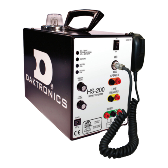
System Setup & Operations HS-200 Indicators, Switches, Knobs & Connections The connection panel of the HS-200 horn start (Figure 3) is where all connection, adjustments, and status indicators are located. 1� The group of four LEDs stacked vertically on the upper left corner performs two functions. -
Page 8: Start System Setup
Start System Setup Reference Drawings: HS-200 Horn Start; On-Deck configuration ............DWG-185695 Refer to Figure 4 (In-Deck) and Figure 5 (On-Deck) for a typical overview when placing the start system components. START HS-200 WALL PLATE #1 DECK PLATE LMI LOCATED BEHIND PLATE... - Page 9 The start system components are shown in Figure 6 – Figure 9. For specific part numbers and options available, refer to DWG-185695 in Appendix A. Figure 7: Horn Start with Internal Speaker Figure 6: HS-200 with Mic Figure 9: Lane Speaker Figure 8: Backstroke Flagpole Speaker Notes: •...
-
Page 10: Connecting The Horn Start
Omega console to the N/C connectors on the HS-200. • If using the HS-200 horn start with a Colorado Timing System console, connect the start cable from the CTS console to the START connectors on the HS-200. Connect the microphone cable into the jack labeled MIC on the HS-200. -
Page 11: Battery Operation
(Figure 12). If the CHARGING LED is off (or flashing) and the BATTERY FULL LED is on, the battery is fully charged. When the HS-200 system is being powered by the battery and is not plugged into the wall, the BATTERY FULL and BATTERY LOW LEDs show battery status. The green BATTERY FULL LED indicates when the battery voltage level is fine for operation. -
Page 12: Configure Start Sound
The LEDs should stop flashing. Enable or Disable Smart Start The HS-200 horn start can detect a connection from the timer console. If the horn start is connected to an OmniSport 2000 timing console, the Smart Start will sense the timer via the dual banana plug extension cable plugged into the START or N/C input. -
Page 13: Enable Practice Mode
2� Turn the power switch on and immediately press and hold both the PUSH TO TALK and top buttons. 3� The horn start speaker will sound off a Start tone. The HS-200 horn start is now in Practice Mode. 4� Cycling the power switch of the HS-200 to will set the horn start back to normal. -
Page 14: Accessories
Figure 16: Remote Strobe UNIVERSAL START INPUT (Figure 16). The other end of the cable should plug into either the START or N/C jack on the HS-200. If the HS-200 is also connected to the OmniSport timer, the remote strobe cable will piggyback onto the timer output cable. -
Page 15: Ac Power Operation & Recharging
Note: For safety reasons, when using the remote strobe near water, use battery power for device operation to minimize the risk of electrical shock. The HS-200 remote strobe operates the same way whether using AC power or battery power. The remote strobe includes a circuit that will recharge the internal battery when the wallpack power supply is connected to a 120 VAC outlet. -
Page 16: Using The Wireless Microphone
Figure 17. 6� Press the side push-to-talk lever and speak into the microphone. The DATA LED on the HS-200 unit should light up. To send a start signal, hold the side push-to-talk lever and press the top button. -
Page 17: Changing Belt Packs
If it is necessary to use more than one HS-200R unit in the same facility – or within 900’ (275 m) of each other – simply set both wireless systems to different channels. Note: A single belt pack CANNOT operate multiple horn starts; a separate wireless belt pack is required to control each HS-200 unit. Accessories... -
Page 18: Troubleshooting
Make sure the READY/RECALL LED is lit and steady. If the BATTERY LOW LED is on, plug the HS-200/HS-200R into the wall outlet and retry. Send up to 4-6 start signals into the remote strobe. The capacitor must be energized first to work properly. If it still does not work, the strobe light must be replaced. -
Page 19: Replacement Parts
Starter Extension Cable; 10' (3 m) W-1426 Starter Extension Cable; 125' (38 m) W-1517 Starter Extension Cable; 200' (61 m) W-1518 Refer to Section 5: Daktronics Exchange and Repair & Return Programs (p�16) for information on exchanging or returning parts. Troubleshooting... -
Page 20: Daktronics Exchange And Repair & Return Programs
Fill out and attach the enclosed UPS shipping document. c� Ship the part to Daktronics. 3� The defective or unused parts must be returned to Daktronics within 5 weeks of initial order shipment� If any part is not returned within five (5) weeks, a non-refundable invoice will be presented to the customer for the costs of replenishing the exchange parts inventory with a new part. -
Page 21: Repair & Return Program
Repair & Return Program For items not subject to exchange, Daktronics offers a Repair & Return Program. To send a part for repair, follow these steps: 1� Call or fax Daktronics Customer Service� Refer to the appropriate number in the chart on the previous page. - Page 22 This page intentionally left blank.
-
Page 23: A Reference Drawings
Reference Drawings Refer to Resources (p�2) for information regarding how to read the drawing number. Any contract-specific drawings take precedence over the general drawings. Reference Drawings: HS-200 Horn Start; On-Deck Configuration ............DWG-185695 Reference Drawings... - Page 24 This page intentionally left blank.
- Page 25 THIRD ANGLE PROJECTION THE CONCEPTS EXPRESSED AND DETAILS SHOWN ON THIS DRAWING ARE CONFIDENTIAL AND PROPRIETARY. DO NOT REPRODUCE BY ANY MEANS WITHOUT THE EXPRESS WRITTEN CONSENT OF DAKTRONICS, INC. OR ITS WHOLLY OWNED SUBSIDIARIES. COPYRIGHT 2017 DAKTRONICS, INC. (USA) OMNISPORT PROJECT:...
- Page 26 This page intentionally left blank.
-
Page 27: B Daktronics Warranty & Limitation Of Liability
Daktronics Warranty & Limitation of Liability This section includes the Daktronics Warranty & Limitation of Liability statement (SL-02374)� Daktronics Exchange and Repair & Return Programs... - Page 28 This page intentionally left blank.
- Page 29 EXCEPT AS OTHERWISE EXPRESSLY SET FORTH IN THIS WARRANTY, TO THE MAXIMUM EXTENT PERMITTED BY APPLICABLE LAW, DAKTRONICS DISCLAIMS ANY AND ALL OTHER PROMISES, REPRESENTATIONS AND WARRANTIES APPLICABLE TO THE EQUIPMENT AND REPLACES ALL OTHER WARRANTIES OR CONDITIONS, EXPRESS OR IMPLIED, INCLUDING, BUT NOT LIMITED TO, ANY IMPLIED WARRANTIES OR CONDITIONS OF MERCHANTABILITY, FITNESS FOR A PARTICULAR PURPOSE, OR ACCURACY OR QUALITY OF DATA. OTHER ORAL OR WRITTEN INFORMATION OR ADVICE GIVEN BY DAKTRONICS, ITS AGENTS OR EMPLOYEES, SHALL NOT CREATE A WARRANTY OR IN ANY WAY INCREASE THE SCOPE OF THIS LIMITED WARRANTY. THIS LIMITED WARRANTY IS NOT TRANSFERABLE. 2. Exclusion from Warranty Coverage This Warranty does not impose any duty or liability upon Daktronics for any: A. damage occurring at any time, during shipment of Equipment unless otherwise provided for in the Agreement. When returning Equipment to Daktronics for repair or replacement, End User assumes all risk of loss or damage, agrees to use any shipping containers that might be provided by Daktronics, and to ship the Equipment in the manner prescribed by Daktronics; B. damage caused by: (i)the improper handling, installation, adjustment, use, repair, or service of the Equipment,or (ii) any physical damage which includes, but is not limited to, missing, broken, or cracked components resulting from non‐electrical causes; altered, scratched, or fractured electronic traces; missing or gauged solder pads; cuts or clipped wires; crushed, cracked, punctured, or bent circuit boards; or tampering with any electronic connections, provided that such damage is not caused by personnel of Daktronics or its authorized repair agents; C. damage caused by the failure to provide a continuously suitable environment, including, but not limited to: (i) neglect or misuse; (ii) improper power including, without limitation, a failure or sudden surge of electrical power; (iii) improper air conditioning, humidity control, or other environmental conditions outside of the Equipment’s technical specifications such as extreme temperatures, corrosives and metallic pollutants; or (iv) any other cause other than ordinary use; Copyright © Daktronics, Inc. SL-02374 Rev 12 19Nov15 Page 1 of 2...
- Page 30 Limitation of Liability Daktronics shall be under no obligation to furnish continued service under this Warranty if alterations are made to the Equipment without the prior written approval of Daktronics. It is specifically agreed that the price of the Equipment is based upon the following limitation of liability. In no event shall Daktronics (including its subsidiaries, affiliates, officers, directors, employees, or agents) be liable for any claims asserting or based on (a) loss of use of the facility or equipment; lost business, revenues, or profits; loss of goodwill; failure or increased cost of operations; loss, damage or corruption of data; loss resulting from system or service failure, malfunction, incompatibility, or breaches in system security; or (b) any special, consequential, incidental or exemplary damages arising out of or in any way connected with the Equipment or otherwise, including but not limited to damages for lost profits, cost of substitute or replacement equipment, down time, injury to property or any damages or sums paid to third parties, even if Daktronics has been advised of the possibility of such damages. The foregoing limitation of liability shall apply whether any claim is based upon principles of contract, tort or statutory duty, principles of ...
Need help?
Do you have a question about the HS-200 and is the answer not in the manual?
Questions and answers