Table of Contents
Advertisement
Advertisement
Table of Contents

Related Manuals for Atlas Equipment WBT-210


Summary of Contents for Atlas Equipment WBT-210
- Page 1 ATLAS WBT-210 TRUCK TIRE WHEEL BALANCER INSTALLATION & OPERATION MANUAL...
- Page 2 PRINTING CHARACTERS AND SYMBOLS Throughout this manual, the following symbols and printing characters are used to facilitate reading: Indicates the operations which need proper care Indicates prohibition Indicates a possibility of danger for the operators BOLD TYPE Important information 2 / 25 REV.
-
Page 3: Table Of Contents
CONTENTS INTRODUCTION 1.1 - INTRODUCTION MACHINE IDENTIFICATION DATA 1.3 MANUAL KEEPING GENERAL INFORMATION 2.1 GENERAL SAFETY STANDARD SAFETY DVICES 2.3 INTENDED USE 2.4 GENERAL CHARATERISTICS 2.5 MACHINE DESCRIPTION 2.6 TECHNICAL SPECIFICATION TRANSPORTATION, UNPACKING AND STORAGE 3.1 TRANSPORTATION 3.2 UNPACKING 3.3 STORAGE COMMISSIONING 4.1 SPACE REQUIRED 4.2 SHAFT ASSEMBLY... -
Page 4: Introduction
CHAPTER 1 – INTRODUCTION INTRODUCTION Thank you for purchasing a product from the line of wheel balancer. The machine has been manufactured in accordance with the very best quality principles. Follow the simple instructions provided in this manual to ensure the correct operation and long life of the machine. Read the entire manual thoroughly and make sure you understand it. -
Page 5: General Information
CHAPTER 2 – GENERAL INFORMATION GENERAL SAFETY The wheel balancing machine should only be used by duly authorized and trained personnel. The wheel balancing machine should not be used for purposes other than those described in the instruction manual. Under no way should the wheel balancing machine be modified except for those modifications made explicitly by MANUFACTURER. -
Page 6: Machine Description
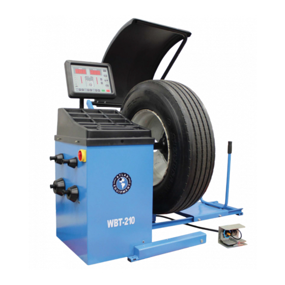
MACHINE DESCRIPTION A. Control panel B. Weight tray C. Body with the main switch and the cone holder D. Distance gauge E. Shaft F. Wheel access ramp G. Wheel lift H. Wheel lift pedal I. Micro switch protection J. Wheel guard Fig. -
Page 7: Transportation, Unpacking And Storage
CHAPTER 3 – TRANSPORTATION, UNPACKING AND STORAGE TRANSPORTATION The machine must be transported in its original packaging and kept in the position shown on the package itself. The packaged machine may be moved by means of a fork lift truck of suitable capacity. Insert the forks at the points shown in figure 2. -
Page 8: Commissioning
CHAPTER 4 – COMMISSIONING 4.1 SPACE REQUIRED When choosing the place of installation, make sure that it complies with current safety at work regulations. Do not operate the balancer while it is on the pallet. The balancer must be located on a flat floor of solid construction, preferably concrete. The balancer must sit solidly on its three feet. -
Page 9: Wheel Guard Mounting
WHEEL GUARD MOUNTING Remove the wheel guard and installation accessories from the package. Mount the wheel guard onto the arm then fix it onto the machine. PANEL INSTALLTION (ref. fig. 6-1) Remove the panel and installation accessories from the package. Mount the panel to the body. -
Page 10: Control Panel And Menu Function
CHAPTER 5 – CONTROL PANEL AND MENU FUNCTION 5.1. CONTROL PANEL Press buttons only with your fingers. Never use the counterweight pincers or other pointed objects. When the beep signal is enabled, pressing of any push button is accompanied by a “Beep”. - Page 11 13. Push button, manual DIAMETER (D) setting 14. Push button, start 15. Push button, emergency/home/braking 16. Push button, confirm 17. Indicator, unbalance reading 5g (25oz) for car mode, <10g (50oz) for truck mode 18. Push button, CAR/TRUCK mode and FUNCTIONS selection 19.
-
Page 12: Menu Functions
MENU FUNCTIONS (figure 8) 12 / 25 REV. 02 2011... -
Page 13: Operation Of The Wheel Balancer
CHAPTER 6 – OPERATION OF THE WHEEL BALANCER Do not use the machine until you have read and understood the entire manual and the warning provided. The wheel guard must not be opened before the wheel stops. The STOP button serves to stop the machine immediately in emergencies. -
Page 14: Wheel Data Entry
Fit the flange or a cone depending on Fig. 9 whether you intend to centre the wheel using a flange or a cone (ref, fig. 9); Place the wheel lift at the lowest height and bring the wheel lift to its fully extended position;... -
Page 15: Balancing Mode
BALANCING MODE Be sure to balance the car wheel in CAR mode and to balance the truck wheel in TRUCK mode. 6.4.1 DYNAMIC MODE The initial screen when switching on is in DYNAMIC mode. The dynamic mode is used for most passenger and light truck wheels using the most common location for corrective weights. -
Page 16: Standard Alu Mode
6.4.3 STANDARD ALU MODE (only for CAR mode) All the ALU modes are dynamic balance. Choose the option that best fits the available locations as shown in the figure 16. From the measurement screen, press to select the modes ALU1 ALU2 ALU3 ALU4. -
Page 17: Unbalance Optimization (Opt)
6.4.4 UNBALANCE OPTIMIZATION – OPT (only for CAR mode) This function is used to determine the best mating of tire and rim that will result in the least amount of total unbalance of the wheel. It severs to reduce the amount of weight to be added in order to balance the wheel. -
Page 18: Set Up
CHAPTER 7 – SET UP SELF-DIAGNOSIS Fig. 16 Diagnosis of phase Rotate the wheel in direction of rotation, the readouts display from 0 to 255. Rotate the wheel in reverse direction of rotation, the readouts displays from 255 to 0. Diagnosis of inner piezo Push the balancing shaft from any direction, the readouts change. -
Page 19: Self-Calibration
SELF-CALIBRATION Make sure to calibrate the machine in CAR mode using a car wheel or in TRUCK mode using a truck wheel. Make sure to entry the exact date of the wheel mounted. Entry of incorrect data would mean that the machine is not correctly calibrated, therefore all subsequent measurements will be incorrect until the new self-calibration is performed with the correct data. -
Page 20: Maintenance
CHAPTER 8 – MAINTENANCE GENERAL WARNINGS Unauthorized personnel may not carry out maintenance work. Regular maintenance as described in the manual is essential for correct operation and long lifetime of the machine. If maintenance is not carried out regularly, the operation and reliability of the machine may be compromised. -
Page 21: Errors And Trouble-Shooting
CHAPTER 9 – ERRORS AND TROUBLE-SHOOTING ERROR DISPLAY During machine operation, various cause of faulty operation can occur. If defected by the micro- processor, they appear on the display as follows: ERRORS: MEANING: SOLUTION: Err -0- The machine is not preset up by the Call for the technical service. -
Page 22: Standard Clamping Accessoires
CHAPTER 19 – STANDARD CLAMPING ACCESSORIES Figure 18 – STANDARD CLAMPING ACCESSORIES P1-12001W Cone D.44-70 P1-12002W Cone D.59-82 P1-12003W Cone D.78-111 P1-12004W Cone D.95-132 P1-50001 Rubber cap P1-50000 Quick nut P3A-00203 Cone D.125-174 P3A-00102 Spacer P3A-00202 Cone D.211-224 P3A-00102 Spacer P3A-00201 Cone D.277-284 P3-61000... -
Page 23: Electric And Pnematic Scheme
CHAPTER 11 –ELECTRIC AND PNEUAMTIC SCHEME Figure 19 - ELECTRIC SCHEME 23 / 25 REV. 02 2011... - Page 24 Figure 20 - PNEUMATIC SCHEME Braking cylinder Flow restrictor Motor clutching cylinder Lift pedal valve Control valve Lubricator Air balloon Pressure regulator Silencer outlet adjuster 1/8” Compressed air supply 24 / 25 REV. 02 2011...
- Page 25 Figure 21 - PNEUMATIC CONNECTION Lubricator + regulator Motor clutching valve Braking valve Motor clutching cylinder Braking cylinder Tee union Air balloon Pedal valve unit 25 / 25 REV. 02 2011...
- Page 26 Warranty This item has a one (1) year LIMITED warranty. Atlas Automotive Equipment warrants the equipment to the ® original purchaser against defects in material or workmanship under normal use for a period of one year from the date of purchase.
Need help?
Do you have a question about the WBT-210 and is the answer not in the manual?
Questions and answers