Table of Contents
Advertisement
Advertisement
Table of Contents

Related Manuals for Atlas Equipment WB55


Summary of Contents for Atlas Equipment WB55
- Page 2 PRINTING CHARACTERS AND SYMBOLS Throughout this manual, the following symbols and printing characters are used to facilitate reading: Indicates the operations which need proper care Indicates prohibition Indicates a possibility of danger for the operators BOLD TYPE Important information 2 / 35 REV.
-
Page 3: Table Of Contents
CONTENTS INTRODUCTION 1.1 - INTRODUCTION MACHINE IDENTIFICATION DATA 1.3 MANUAL KEEPING GENERAL INFORMATION 2.1 GENERAL SAFETY STANDARD SAFETY DVICES 2.3 INTENDED USE 2.4 GENERAL CHARATERISTICS 2.5 MACHINE DESCRIPTION 2.6 TECHNICAL SPECIFICATION TRANSPORTATION, UNPACKING AND STORAGE 3.1 TRANSPORTATION 3.2 UNPACKING 3.3 STORAGE 3.4 SCRAPPING COMMISSIONING 4.1 SPACE REQUIRED... - Page 4 7.4 CALIBRATION OF B GAUGE 7.5 GENERAL SETTINGS 7.6 SELF-DIAGNOSIS 7.7 MULTI-LANGAGUE SETTINGS 7.8 SYSTEM INFORMATION ERRORS TROUBLE-SHOOTING MAINTENANCE ACCESSORIES ELECTRIC DIAGRAM 4 / 35 REV. 01 2012...
-
Page 5: Introduction
CHAPTER 1 – INTRODUCTION INTRODUCTION Thank you for purchasing a product from the line of wheel balancer. The machine has been manufactured in accordance with the very best quality principles. Follow the simple instructions provided in this manual to ensure the correct operation and long life of the machine. Read the entire manual thoroughly and make sure you understand it. -
Page 6: General Information
CHAPTER 2 – GENERAL INFORMATION GENERAL SAFETY The wheel balancing machine should only be used by duly authorized and trained personnel. The wheel balancing machine should not be used for purposes other than those described in the instruction manual. Under no way should the wheel balancing machine be modified except for those modifications made explicitly by MANUFACTURER. -
Page 7: Machine Description
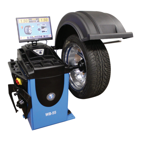
Rapid optimization (OPT) Self-diagnosis Self-calibration Display in grams or ounces, in mm or inch Anchor-down installation unnecessary MACHINE DESCRIPTION A: LCD monitor B: Control panel C: Wheel weight tray D: Main switch E: Tool shelf F Cone holder G: Foot brake H: Balancing shaft I: Quick nut and cones J: Wheel guard... -
Page 8: Transportation, Unpacking And Storage
CHAPTER 3 – TRANSPORTATION, UNPACKING AND STORAGE TRANSPORTATION The machine must be transported in its original packaging and kept in the position shown on the package itself. The packaged machine may be moved by means of a fork lift truck of suitable capacity. Insert the forks at the points shown in figure 2. -
Page 9: Commissioning
CHAPTER 4 – COMMISSIONING 4.1 SPACE REQUIRED When choosing the place of installation, make sure that it complies with current safety at work regulations. Do not operate the balancer while it is on the pallet. The balancer must be located on a flat floor of solid construction, preferably concrete. The balancer must sit solidly on its three feet. -
Page 10: Wheel Guard Mounting
WHEEL GUARD MOUNTING Fig. 6 Remove the wheel guard and installation accessories from the package. Mount the guard onto the guard arms fixed on the machine. Tighten the screws. Mount the wheel guard onto the guard frame. Check the micro switch is held down when the guard is closed. -
Page 11: Control Panel And Menu
CHAPTER 5 – CONTROL PANEL AND MENU CONTROL PANEL Press buttons only with your fingers. Never use the counterweight pincers or other pointed objects. When the beep signal is enabled, pressing of any push button is accompanied by a “Beep”. Fig. -
Page 12: Switch On
SWITCH ON When the machine is switched on, the initial screen displays and seconds later changes to the measurement screen (ref. fig. 8). Fig. 8.2 Fig. 8.1 MEASUREMENT SCREEN Fig. 9 – MEASUREMENT SCREEN 1. Amount of unbalance, inner side 2. -
Page 13: Balancing Mode Selection
4. Unbalanced positions for both inner side and outer side of the rim 5. Wheel dimensions measured 6. User selected 7. Approx/fine readings 5g/1g or 0.25oz/0/1oz selection 8. Manual settings of wheel dimensions 9. Balancing modes selection 10. Units (gram or ounce) selection 11. -
Page 14: Operation Of The Wheel Balancer
CHAPTER 6 – OPERATION OF THE WHEEL BALANCER Do not use the machine until you have read and understood the entire manual and the warning provided. The wheel guard must not be opened before the wheel stops. The STOP button serves to stop the machine immediately in emergencies. -
Page 15: Standard Back Cone Mounting
6.2.1 STANDARD BACK CONE MOUNTING (ref. Fig. 12) Carefully clean the component surface before performing any operation. Most steel wheels can be mounted properly using this method. The wheel is centered on a cone from the inner side of the hub. Fig. -
Page 16: Automatic Setting Of Dimensions
Fig. 14 – STANDARD MODES Fig. 15 – ALU MODES 6.3.2 AUTOMATIC SETTING OF DIMENSIONS 6.3.2.1 STANDARD MODES Move the A/D gauge to measure the A and D dimensions as shown in the figure 16. The dimensions A and D are determined and set automatically, and a beep sound is heard in the meantime. -
Page 17: Manual Setting Of Dimensions
6.3.2.2 ALU MODES Move the A/D gauge to the position “1” as shown in the figure 18, select and press SELECTOR to confirm. The dimensions A1 and D1 are set automatically, and a beep sound is heard in the meantime. The set dimensions are shown on the screen after releasing the gauge. Fig. -
Page 18: Balancing Mode
BALANCING MODES During spinning, do not raise the wheel guard or press STOP button, do not press the brake pedal. The spin cannot be completed and the error information will be shown on the screen. A spin can be performed by pressing START button or closing the wheel guard if START BY LOWERING GUARD is enabled. -
Page 19: Static Mode
Tips (ref. fig. 24): Select and press SELECTOR to show the fine readings of unbalanced amounts. Select and press SELECTOR to convert the reading units (gram or ounce). Select and press SELECTOR to show the unbalanced positions of the rim in 3D graph. Fig. -
Page 20: Unbalance Optimization (Opt)
6.4.3 UNBALANCE OPTIMIZATION (OPT) This function is used to determine the best mating of tire and rim that will result in the least amount of total unbalance of the wheel. It severs to reduce the amount of weight to be added in order to balance the wheel. -
Page 21: Alu Mode
6.4.4 ALU MODES All the ALU modes are dynamic balance. The program of this machine includes seven ALU balancing modes from ALU1 to ALU7 for application of alloy rims with the different profiles (ref. fig. 33). To perform the ALU balancing, do as follows: Select the mode that best fits the available locations. - Page 22 To perform ALU balancing, do as follows: Select the mode ALU1 or ALU2 that best fits the available locations. Measure wheel dimensions automatically or manually. Be sure to set the dimensions referring to the chapter 6.3.2.2 for modes. Start a spin. Fig.
-
Page 23: Split Function
6.4.5.2 CORRECTION OF OUTER SIDE Apply the weight onto the position indicated by the arrow shown on the screen (ref. fig. 41) following the same procedures for correction of inner side. In case that the unbalanced amounts are left on the outer side of the rim, it is advisable to perform SPLIT function. -
Page 24: Motorcycle Mode
Press SELECTOR again and the program will return to the dimension screen. Two unbalanced points will be shown on the outer side of the rim on the screen for corresponding to the two spokes (ref. fig. 46). Fig. 46 Rotate the wheel to any unbalanced point on the outer side of the rim, the readings on the right window of the screen will be changed from 50k to 30g and 25g, and the unbalanced points are... -
Page 25: Setup
CHAPTER 7 – SETUP On the measurement screen, press MENU/SAVE key to access the menu setup screen on which eight configurations are available. Each configuration can be selected by turning and pressing SELECTOR. On the left side of the screen: On the right side of the screen: Multi-users General settings... - Page 26 To make the weight calibration, select press SELECTOR and then proceed as the diagram shown on the screen (fig. 50): Fig. 50 Mount a wheel with average dimensions on the shaft. Be sure the wheel is not mounted with any weight.
-
Page 27: Calibration Of A/D Gauge
CALIBRATION OF A/D GAUGE Fig. 54 Select and press SELECTOR to entry the A/D gauge calibration program. Turn SELECTOR TO select A or D shown on the screen. The item highlighted in red is selected (ref. fig. 54). Press SELECTOR to make the calibration for the item selected. -
Page 28: Calibration Of B Gauge
CALIBRATION OF B GAUGE Fig. 60 Select and press SELECTOR to entry the B gauge calibration program (fig. 60). Place the gauge to the “0” position as shown in Fig. 61 the figure 61. Press SELECTOR to memorize the position. Set the gauge head to the outer surface of the Fig. -
Page 29: Self-Diagnosis
SELF-DIAGNOSIS Select and press SELECTOR to entry the diagnosis program (fig. 63). Select each item by turning and pressing SELECTOR. Check the dynamic status of each item shown on the right side of the screen. Exit by pressing both SELCTOR and STOP/ESC keys at same time. -
Page 30: Multi-Langague Settings
MULTI-LANGUAGE SETTINGS Select and press SELECTOR to entry the multi-language settings. Select the language item by turning SELECTOR. The selected language is highlighted in red Turn SELECTOR to select the language and confirm by pressing it. Press STOP/ESC key to exit. Fig. -
Page 31: Errors
CHAPTER 8 – ERRORS Fig. 66 START button is pressed when the wheel guard is not lowered and, if START BY LOWERING GUARD is enabled. Fig. 67 The wheel guard is raised when the machine is spinning. Fig. 68 A/D gauge is not moved to the correct position when the gauge is needed to be set measurement. -
Page 32: Trouble-Shooting
CHAPTER 9 – TROUBLE-SHOOTING ROUBLE OSSIBLE AUSE OLUTION No display when 1. There is no power. 1. Check power on. switching on 2. The faulty power plug. 2. Replace. 3. The electrical wires are 3. Reconnect. disconnected. 4. Check for correct voltage. 4. -
Page 33: Maintenance
CHAPTER 10 – MAINTENANCE 10.1 GENERAL WARNINGS Unauthorized personnel may not carry out maintenance work. Regular maintenance as described in the manual is essential for correct operation and long lifetime of the machine. If maintenance is not carried out regularly, the operation and reliability of the machine may be compromised. -
Page 34: Accessories
CHAPTER 11 – ACCESSORES 11.1 STANDARD ACCESSORIES 1. P1-50000 Quck locking nut TR40X3 2. P1-50005 Pressure cup 3. P1-12001W Cone D.44-70 4. P1-12002W Cone D.59-82 5. P1-12003W Cone D.78-111 6. P1-12004W Cone D.85-132 11.2 OPTIONAL ACCESSORIES PF-211 Universal flange Universal flange for wheels with/without central hole, suitable for any vehicle wheel with 3-4-5 holes. -
Page 35: Electric Diagram
CHAPTER 12 – ELECTRIC DIAGRAM 35 / 35 REV. 01 2012... - Page 36 Warranty This item has a one (1) year LIMITED warranty. Atlas Automotive Equipment warrants the equipment to the ® original purchaser against defects in material or workmanship under normal use for a period of one year from the date of purchase.
Need help?
Do you have a question about the WB55 and is the answer not in the manual?
Questions and answers