Table of Contents
Advertisement
Quick Links
You can expect updates to this manual over the next few months
Do NOT read this entire manual... unless you want to.
•
At the start of Chapters 1 - 4 are short sections with references to find what you need plus some important
reminders. PLEASE read these short sections at the very least and refer back to them, when needed.
•
Chapters 1 and 2 are very important in terms of correctly setting up your Skycut to work with SignCut Pro2
and learning the ins and outs of cutting.
•
Chapter 3 is for those owners wanting to perform print and cut applications.
•
Chapter 4 covers using Skycut accessory tools and dual head applications.
•
Chapter 5 covers several SignCut Pro2 functions of interest: creating contour cuts and engraving fills.
It's not practical to print this entire manual because:
•
It's a waste of paper and ink if you only ever need certain sections.
•
The live links to videos and web sites in the manual will not work.
•
This manual will be updated from time to time.
•
You cannot search on individual words.
Also:
•
Videos of interest can be found at the following link:
________________________________________________________________
© 2018-2020
Sandy McCauley All Rights Reserved
Skycut Series D with SignCut Pro2
July 3, 2020
Skycut Support Videos
1
Advertisement
Table of Contents

Related Manuals for Skycut D Series


Summary of Contents for Skycut D Series
-
Page 1: Skycut Series D With Signcut Pro2
PLEASE read these short sections at the very least and refer back to them, when needed. • Chapters 1 and 2 are very important in terms of correctly setting up your Skycut to work with SignCut Pro2 and learning the ins and outs of cutting. -
Page 2: Table Of Contents
Table of Contents SKYCUT SERIES D WITH SIGNCUT PRO2 ............1 1. INTRODUCTION AND SETTING UP ......................... 5 1.00 Q ......................5 UICK EFERENCE FOR HAPTER 1.01 S ............................... 5 UPPORT 1.02 S ..........................5 AFETY AND ARNINGS 1.03 W .............................. - Page 3 EFORE 2.08 S ............................. 79 CALE ALIBRATION 2.08.1 Skycut Resolution Using Millimeters for Measurement ..............79 2.08.2 Skycut Resolution Using Inches for Measurement ................82 2.08.3 Scale Calibration Storage on the Control Panel ................. 83 2.09 T ....................86 UTTING...
- Page 4 4.02.1 Draw and Cut ............................ 117 4.02 E ......................... 119 MBOSSING AND CORING 4.02.1 General Info on Embossing ......................119 4.02.2 Score and Cut Project ........................119 4.02.3 Embossing Paper or Cardstock ......................120 4.03 S ..........................121 CRATCH NGRAVING 4.03.1 Engraving a Metal Tag ........................
-
Page 5: Introduction And Setting Up
• If you run into difficulties with the operation of your Skycut, turn off the power and look for a solution in this manual. Note that Appendix A is a Troubleshooting section. If you continue to have technical questions or issues, please contact your dealer as soon as possible. -
Page 6: Warranty
Always turn off the Skycut before unplugging or removing the power cable from the wall outlet or power strip. • Unplug the Skycut from a wall outlet or power strip during an electrical storm or when the cutter will not be used for an extended period of time. •... -
Page 7: Parts Of The Skycut
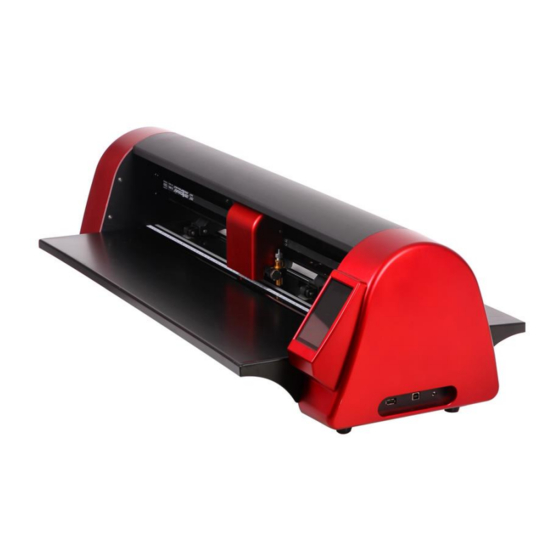
Power cable USB Cable 60° Blade(blue cap) 45° Blade(red cap) Blade Holder Test Pen and 1 Refill 2 sets Cutting Mat 1.06 Parts of the Skycut Front Cutting Strip Alignment Marker (lt. gray) Pinch Wheel Control Panel Right End Cap... -
Page 8: Right Side
USB Flash Drive Port: used to load PLT files via control panel for cutting • USB Port: option to connect computer to Skycut with included USB cable • Reset Button: used to reset Skycut’s cutting buffer (does not reset calibrations) Reset USB Flash USB Port Button... -
Page 9: Accessories
• The screws required for attaching are already installed in the Skycut. They will be removed and then, after aligning the holes in the table, replaced to securely attach the table. •... -
Page 10: Test Pen
1.07.2 Test Pen • The test pen should be used until you are comfortable with the operation of your Skycut and know, with certainty, where images will cut. The test pen should arrive pre-assembled. However, if you want to change... -
Page 11: Blade Installation
• Note that the red capped blade and blue capped blade have a cutback on the opposing side of the blade (right side, in the earlier photo). This reduces the blade offset value and allows for better detailed cutting of small shapes. -
Page 12: Preparing And Caring For The Cutting Mat
• Do not leave the pinch wheels in a down position when the Skycut isn’t in use. This warps the plastic sooner, shortening the useful life of the cutting mat. 1.08.2 Cleaning and Replenishing the Cutting Mat •... -
Page 13: Pinch Wheels
• When necessary, the rubber wheels and the grit shafts may be cleaned with isopropyl alcohol or Un-Du. Apply the cleaner to a clean lint-free rag and rub the entire wheel and/or grit shaft until free of adhesive. 1.09 Pinch Wheels •... -
Page 14: Control Panel
1.10 Control Panel • When you first turn power on the Skycut, after several seconds, the following Main Screen or Home Screen will be displayed: Repeat last cut. While cutting, this icon and function changes to Pause. -
Page 15: Introduction To Sign Cut Pro 2
1.11 Introduction to SignCut Pro 2 1.11.1 Installing SignCut • SignCut Pro 2 can be downloaded from the following link: https://signcutpro.com/#download-section • In some cases, a virus protection software may warn users that there are potentially dangerous files. It is perfectly safe to install this program so temporary changes or disabling of your virus protection program may be required. - Page 16 SignCut Draw: Menu Bar Help Panel Toolbar Properties & Functions Bar Sign Area Tools Design Board Panel Filter Colors & Objects Panel View Options Rulers Shapes Margins Project Bar Color Palette Design Board Bar Status Bar • Hovering your mouse over most of the screen icons will pop up the icon’s name and available shortcut. ...
-
Page 17: Signcut Pro2
1.12 Connecting the Skycut to Your Computer • Place your Skycut on a sturdy horizontal surface. If using the cutting mat, be sure to allow enough free room in both the front and the back for the mat to extend during cutting. -
Page 18: Usb Connection
• Powering On: Plug the power cord into a wall outlet or power strip. Connect the power cord to the Skycut D on the left side end cap. Turn on the power using the power button that is also on the left side end cap. After several seconds, the light inside the Skycut will turn on and the head will do a slight jog. -
Page 19: Wi-Fi Connection
• Note: Not all routers have the same signal strength. It’s usually best to connect the Skycut while it is in the same room with the router. Once connectivity is established, you can then experiment to see how far from the router the Skycut can be located. - Page 20 Click on Scan Click on Wifi (2) Click on the Scan button and a list of the available networks will appear. Select your home/office network and click on Apply. You will then be returned to the Wifi screen: Select your network Click on Set Click on Apply...
- Page 21 IP Address, if needed (6) Next check the IP Address that will be assigned to the Skycut. The Skycut will automatically pick up the first three sets of digits from your router but will continue to display them as shown above. You only need to decide if the last set, which should be defaulting to “200”, can be used.
-
Page 22: Wireless Stand-Alone
• In the drop-down menu for Output Device/Port, select TCP/IP and a new window will open. In that window, enter the same IP Address you selected earlier on the Skycut’s control panel. Also, enter 8080 for the Port assignment: Select TCP/IP... - Page 23 A. The Skycut has never been set up wirelessly to a network • Power on the Skycut and wait for the light to come on. • On your computer, open your list of available networks. In the list, you should see one with this type of name format: HI_LINK_XXXX where “XXXX”...
-
Page 24: Usb Flash Drive
• To reset the Skycut so that it will be found as an available network, press and hold the Default button for 3 seconds. Release and you should see the Apply button now displaying Wait. In a minute the Apply should return and you can then proceed back to A. - Page 25 Enter a file name Click on Save • After saving the file, eject the flash drive and insert it into the USB port on the right side of the Skycut. On the control panel, select USB and then Open File:...
- Page 26 Press Open File Set up repeats, refer to Section 1.14.1 (1) Double tap on USB DISK and a screen will open showing any folders and PLT files on the flash drive. Double tap a folder to open it, as needed. Drag the scroll bar on the right to see more files: Double tap here Drag here to scroll (2) Once you have located the PLT file you want to cut, double tap the name.
-
Page 27: Test Draw Shapes
• New owners tend to be VERY eager to try out their Skycut. It’s important to test your cutter to ensure that data is being sent properly from your computer to the cutter. The following steps will allow you to do some testing with the pen tool. - Page 28 • Use any of the horizontal markings at the front of the Skycut (such as the ruler) to align the mat so that it’s straight. Lift the pinch lever to drop the pinch wheels onto the cutting mat. Most of the mat and the paper should now be behind the cutter, not in the front.
-
Page 29: Default Settings In Signcut Pro
Another setting to verify before proceeding with the testing and all subsequent cutting is to verify that the correct rotation is set for your Skycut. To do this, go to Cutter>Settings and click on the Advanced settings tab. Verify the Rotate setting is set to 90 deg:... -
Page 30: Adding A Test Shape To Draw
Click on Advanced settings Set to 90 deg Click on Ok The third setting is at the top of the Color toolbar on the right side of the screen. This tutorial will cover both options but, for now, click the top icon to the Whole Area setting (if needed) so that it looks like the one in the following screenshot. - Page 31 Skycut before you begin cutting actual projects. Click on the Arrow option: Menu of available basic shapes Select the Arrow • Left click once in the Sign Area and then move the cursor towards the right and down to create an arrow which points towards the right.
-
Page 32: Drawing The Shape From Signcut Pro
The top right portion of the window shows a preview of the arrow and the orientation in which it will be drawn relative to the origin you set on the Skycut (which is represented by the blade holder image. In this case the arrow will be pointing upwards as you face the Skycut. - Page 33 • At this point, if you plan to export this file to a USB flash drive, rather than cut directly to the Skycut from SignCut Pro, please go to Section 1.12.4 for instructions. Otherwise, click on Cut out and the Skycut will...
- Page 34 Feed the mat this direction into the Skycut The arrow is drawn in the same location as in the Work Area and points upwards • You’ll note that the arrow is drawn in the same location as it was positioned in the Work Area. Often, however, users will prefer to save on material and have shapes cut as close as possible to the origin set on the material.
- Page 35 Feed the mat this direction into the Skycut The arrow is drawn at the origin and points to upwards • If you want the arrow to draw so that it points towards the left instead of upwards, click once on the Rotate 90 degrees icon on the Sub-toolbar at the bottom of the screen.
-
Page 36: Default Settings To Consider
In the above screenshot, the shape sent to the Skycut would cut 3 across and 7 up & down, for a total of 21 shapes. The spacing between each shape would be 0.20 inches (Note: to use mm instead of inches, switch the Units setting. - Page 37 • To right power on: With this setting turned on, the cutting head will move to the far right whenever the Skycut is powered on. • Y Key Mode: This setting controls the movement of the material or cutting mat when using the up and down...
-
Page 38: General Settings
Pressing an UP arrow will move Pressing an UP arrow will move the the material forward material towards the back of the cutter Pressing a DOWN arrow will move material towards the back Pressing a DOWN arrow will move of the cutter material forward •... - Page 39 • LED set allows you to change the brightness of the light inside the Skycut or even turn it off: Drag to change the intensity of the light Turn off light • Screen and alarm has two settings: Screensaver time: Set a black-out time, in minutes, for the control panel ...
-
Page 40: Sys Information
This initial screen displays current version numbers. If you ever need to reset your Skycut, press and hold Default All until it turns red. Then wait for the button to update to Success! If you ever need to change which software is in use with your Skycut, press and hold SOFT for two seconds and release. -
Page 41: Maintenance
Flexi/Signcut option and the Signmaster/SCAL option, thus no need to change when using SignCut Pro. 1.15 Maintenance Skycut machines do not require any kind of lubrication or routine checks. However, here are a few things to keep in mind for successful operation of your cutter: •... - Page 42 Awl or Paper Piercer (or other sharp pointed tool): (1) to pick or lift out a test cut to verify results Stabilizers: A stabilizer is an adhesive material that is applied to the bottom of the material you are cutting so that cleaner cuts can be achieved.
-
Page 43: Cutting
• The key to becoming successful at cutting is to do a lot of it. Those who shy away from using their Skycut will never get to the stage of mastering it. It’s very normal for new owners to be intimidated by their cutter, so remember the following key things: ... -
Page 44: Record Your Successes
The recommended method for loading the test pen or another accessory: Place the spacer on top of the material, with the material loaded into the Skycut. Loosen the screw on the blade holder seat and insert the tool so that the tip of the tool is touching... -
Page 45: Adjust The Speed, Force, And Number Of Passes Based On The Material And Shapes
• You have two options: (1) Perform the built-in test cut on the Skycut itself using the Test option on the Main Screen or from within the Speed/Force Screen. (2) Select any basic shape and size it to be around 0.3” – 0.5” (~ 8 mm – 13 mm): Use the same instructions from Section 1.13.3 to add a basic shape for cutting. -
Page 46: Choices Before Cutting
2.02 Choices Before Cutting • There are a number of factors under your control for cutting: What shapes to send to the cutter: Section 2.02.1 Where the shapes will be cut from the material: Section 2.02.2 What tool(s) will be used for cutting (or drawing, scoring, engraving, etc.): Section 2.02.3 ... - Page 47 • There are several methods of selecting which color shapes to send to the cutter: Option 1: If all shapes are showing, then all shapes will be sent to cut: Option 2: Click on any color thumbnail and only those shapes will be displayed. Those will be sent to cut.
- Page 48 Option 5: Instead of selecting by color, you can also mark individual shapes to be cut, excluding others that are still displayed: Click on the Tools for objects icon on the left side Main Panel. In the Sub-toolbar at the bottom of the screen, the following icons appear: Setup path(s) attributes Marking tool...
-
Page 49: Controlling Where Shapes Will Cut
Click on the Cut out icon and, in the preview window, these two selected shapes are the only two present for cutting and have been arranged to optimize material usage: 2.02.2 Controlling Where Shapes Will Cut • The top icon on the Color toolbar is a setting which switches between Whole area and Optimized. -
Page 50: Where To Enter Cut Settings
The bounding box of the shapes is now aligned at the origin • In what applications is one mode preferable over another? Use Whole area mode when it matters where shapes are cut from the material: Two tool applications, such as when scoring with a scoring tool, followed by cutting with the blade holder When engraving on existing objects, such as trophy labels or charms When cutting from a specific location, such as the center of a piece of material... - Page 51 Force and Speed setting on Skycut’s control panel will be used. You haven’t entered specific settings by color or by selected shapes (as will be covered in the subsequent options) ...
- Page 52 Enter Force and Speed Enter Pounce (dashed line) settings (refer to Section 2.03.6) Rotary engraving settings (not applicable to Skycut use) • Color Toolbar Use this option instead of the Advanced settings tab to assign cut settings to each color:...
- Page 53 First, left click on a color thumbnail on the Color Toolbar to select the shapes of that color and hide those of other colors. If another color will share the same cut settings, then hold the Shift key and left click on that color (or more, as appropriate). Right click on any of the selected thumbnails and the same Set Attributes window will open where settings can be entered.
-
Page 54: Cut Settings
“sliver blade.” • As noted earlier, this setting can be made on the Skycut control panel instead. Press the Force/Speed icon and then set the FORCE to the desired level. 2.03.2 Cut Speed and Up Speed •... -
Page 55: Blade Offset
Cut Speed and Up Speed, please use the control panel for this setting. • On the Skycut control panel, the default setting is to have the Up Speed and Cut Speed the same and referred to as SPEED. This can be adjusted by pressing the Force/Speed icon and then setting the SPEED to the desired level. -
Page 56: Overcut
2.03.4 Overcut • Overcut is related to Blade Offset in that it isn’t needed when using a pen, embosser, engraver, and so forth, because the tips of those tools are aligned with the center of the tools themselves. However, leaving Overcut at 0 when using the blade holder will result in large shapes not quite closing: Overcut is too low: paths do not close... - Page 57 • Passes can also be set on the Skycut control panel when, for example, a cut is being made using a USB flash drive. However, unlike using Passes from SignCut Pro, the blade does not stay down to repeat the cut.
- Page 58 Select Use Double Head Press the USB button on the Main Screen and you will see a Passes button in the window which opens: Press Passes Press the Passes button to open the following screen: Mark this option to activate Passes With the upper option selected, Choose the recut mode based on the screen will display Recut...
-
Page 59: Pounce (Dashed-Line Cutting)
Passes • IMPORTANT: Currently the Open recut option will default to off whenever the Skycut is first powered on. Thus, make a mental note (or, even better, put a Post-It note on your cutter) to turn this option on when using multiple passes in dual head operations. -
Page 60: Presets
Presets allow you to save your settings for a particular material or application, such as cutting posterboard or scoring cardstock. A preset can be entered in SignCut Pro or saved on the Skycut control panel. 2.04.1 Saving a Preset in SignCut Pro •... - Page 61 Even if you are not using the right side for a particular material, make sure the control panel is set to Double under Set>Advanced Settings. Otherwise any presets entered will be automatically assigned to the right side. Because settings for any given material or application would need to be entered twice to make those settings available for both right and left sides, consider which side you might always choose to use.
- Page 62 Select an Select unused box Rename Press one of the unused preset boxes, e.g. name5, and it will turn blue indicating it is highlighted. Select Rename. A window opens where you can enter the name for the new Preset. The characters are entered in the same manner as the Password entry window in Section 1.12.2.
-
Page 63: Setting The Origin Before Cutting
• IMPORTANT! The Skycut D24 has a maximum cutting width of 24 inches. If you move the head too far to the left to begin the cut and your project is wide, you may exceed the left side limit and cutting will stop at that point with no option but to abort. -
Page 64: Setting An Origin Using The Camera
If you do choose the latter, make sure there’s a way to clearly distinguish which intersection you want to use. (3) On the Skycut’s Main Screen, use the arrows to move the center of the blade holder roughly over the origin target. In this example, a dot will be used. - Page 65 (4) Select Set and Camera. In the Camera Screen, press OK. A photo will be taken and displayed. If needed, press X3 so that you are zoomed out and able to see the origin target (dot) in the photo: Origin Target (dot) Blue dashed + Red + (5) Press the center of the origin target in the photo so that the...
-
Page 66: Other Cut Setting Functions
2.06 Other Cut Setting Functions • There are other functions and features available in SignCut Pro and on Skycut’s control panel that will be useful depending on your applications. Some have already been covered. Some will be covered in this section. -
Page 67: Mirror
Select from these three options Use “-“ and “+” buttons to set an advance amount to start will cause the blade holder to return to the origin after cutting. to end will cause the blade holder to advance forward to the end of the cut project. ... - Page 68 Inverted Short weed Normal vertical weed line rectangle weed line Normal horizontal Delete all weed lines weed line Short Detailed Automatic weed line weed line weed lines • Before covering each option, note the following: For most of the functions, left clicking the mouse will add a weed line. Holding Shift and/or Ctrl will provide additional options.
- Page 69 Hold the Ctrl key and left click to add short horizontal weed lines Holding both the Shift key and the Ctrl key while clicking allows you to add short vertical weed lines, as needed. • – Left click once where you want a vertical weed line added: Normal Vertical Weed Line Click to add a vertical weed line ...
- Page 70 Left click to add short horizontal weed lines Hold the Shift key and left click to add short vertical weed lines • Inverted Weed Line - In some cases, such as stencil applications, the part being weeded is the opposite. Thus, what is normally the waste part of the material is the part being kept. Thus, in this example, it would be the letters themselves being weeded away, so having weed lines inside the letters would be desirable.
-
Page 71: Tiling Options
Drag mouse from here to here Rectangle is created with extending lines • Automatic Weed Lines - Automatically adds weed lines to the design. Left click to add horizontal lines and/or Shift + left click to add vertical lines: Left click here Shift + left click here ... - Page 72 Tiles Panel • In some cases, the limiting factor which leads to the need for tiling is the maximum cutting width of the cutter. In other cases, as presented here, the limiting factor is the width of the material available. •...
- Page 73 Click on Create tiles to generate tiles based on current size settings Tile 4 Tile 3 Tile 2 Tile 1 Note that the Width indicated as 10.9843” instead of 11” is a programming round-off error and is neglible in size. •...
- Page 74 In the Cut out window, only the top tile appears These three tiles are deactivated Activate/deactivate tiles selected • The Cutout window has additional tile settings whereby you can have copies of tiles made and specify the distance between each copy. For example: Copies set to 3 with a spacing of 0.25”...
- Page 75 Note the purple dashed line indicates that the design exceeds the maximum cutting width of the C16 Skycut, which will be used. This purple line is automatically the first tile line. • Before covering each option, note the following: ...
- Page 76 Click to add a vertical tile line Add vertical tile line selected Hold the Shift key while clicking and instead of creating a vertical line, another horizontal tile line will be added. While there is a second option on the sub-toolbar for adding horizontal tile lines, it can be more convenient to add them while in Vertical tile line mode if you’re needing both types.
- Page 77 Left click to add a short vertical tile line Left click to add a short vertical tile line Add short vertical tile line selected • Manual tile overlap - Some users prefer to have a small amount of overlap in the tiles so as to avoid any possible gap when aligning the cut pieces.
-
Page 78: Important Checklist Before You Cut
2.07 Important Checklist Before You Cut! • Do you have your material on the mat and the mat inserted into the Skycut? (Note: materials with a backing sheet, such as vinyl and iron-on transfer do not require a mat for cutting) •... -
Page 79: Scale Calibration
Before beginning the calibration, it’s a good idea to make sure the Scale values which can also be stored on the Skycut’s control panel are set at a default of 1. Go to Set>Advanced Settings> Scale. The following window opens: Verify X Scale and Y Scale are both set to 1.0000... - Page 80 • Using a mm ruler, carefully measure the Width (the left-to-right length that drew) and the Height (the top-to- bottom length that drew: Feed the mat this direction into the Skycut Width, X Height, Y • Write those measurements onto your sheet:...
- Page 81 • Verify that the units are set to Millimeters on the Cutter Panel. If not, click on the button until Millimeters is displayed: Click here to change untis to Millimeters • To open the Calibrate cutter size window, click on the Cutter button on the Cutter Panel. Select the Advanced settngs tab and, in that same window, click on the Calibrate cutter size button (lower right corner): Click on Advanced...
-
Page 82: Skycut Resolution Using Inches For Measurement
2.08.2 Skycut Resolution Using Inches for Measurement • In SignCut Draw, go to Settings>Settings and select inch: Select inch (in) • With the square still selected, change the width and height to the largest size that will fit on the paper you have available. -
Page 83: Scale Calibration Storage On The Control Panel
• Use a calculator to convert the fractions to decimals. In the example here, the Width would be 9.94 amd the Length would be 10.03. • Verify that the units are set to Inches on the Cutter Panel. If not, click on the button until Inches is displayed: Click here to change untis to Inches... - Page 84 • The Scale Calibration results can be stored on the Skycut’s control panel instead of within SignCut Pro. To do this, you’ll need to calculate the actual scaling value based on the results you ended up entering in SignCut Pro.
- Page 85 Draw the square again and measure to verify the square is now 10 in x 10 in. • Once you have your calibration set, please record these values in your “little black book” in case you ever need to reset your Skycut to default settings or install a firmware update.
-
Page 86: Test Cutting Flow Chart For The Skycut
• Select a small test shape. You can use the built-in test on the Skycut. However, a shape w ith an internal path, such as a ring, works better as it allows you to more easily check to see if the blade is cutting into the backing sheet or cutting mat. -
Page 87: Settings Form For Cutting Materials
2.10 Settings Form for Cutting Materials Material Brand or Blade Material Blade Force Speed Other Comments Source Offset Passes © 2009- 2020 Sandy McCauley, All Rights Reserved... -
Page 88: Suggested Settings For Various Materials
2.11 Suggested Settings for Various Materials IMPORTANT: These settings should be used for the initial test cut only. Adjustments may be necessary based on the condition of the blade, variations in the material, humidity, condition of the cutting mat, blade tip height, etc. - Page 89 Material Type Material Brand/Source Blade Passes Force Speed Other Comments Tracing Paper Helix Vellum Paper Vinyl - Heat Transfer Siser EasySubli - with the mat Cut on the mat Siser Glitter - Gold - No cutting 2 passes makes it easier to weed, also slight Vinyl - Heat Transfer 35-40 scratch cut in the backing layer...
-
Page 90: Print And Cut (Contour Cut)
The print and cut process (also called PNC and contour cutting) involves printing an image from SignCut Pro2 to any printer you own and then, with the aid of the Skycut’s camera, have the image or images cut out with perfect precision. Below are three typical kinds of print and cut applications but there can be other kinds. -
Page 91: What Is Apnc Calibration
3.03.2 Calibration Process (1) Insert the test pen into the Skycut on the left side blade holder seat. Place the sheet of paper into the Skycut. You can use the cutting mat to hold the paper or insert the paper directly. - Page 92 Select Use L Head (P0) (4) Select Speed/Force and set SPEED to ~ 8 and FORCE to ~ 30. Click on Test to verify that a square is clearly drawn. If it is too faint, increase FORCE as needed and repeat. (5) Move the pen an inch or two away from the test so that there is room for the calibration shape to be drawn.
- Page 93 Press Adjust button… … and Start button appears (8) Press Start. The test shape, which is a square with a inside, will be drawn on the paper and the camera will move over the test shape, take a photo, and display the photo on the control panel. If you cannot see the test shape clearly, press the LED button once so that it reads LED 50% and press the Get PIC button.
-
Page 94: Performing Apnc In Sign Cut Pro
(14) Press X3 to return to normal magnification. Click on the Home icon to return to the Main Screen. Your Skycut is now calibrated for print and cut (PNC) applications. 3.04 Performing a PNC in SignCut Pro 3.04.1 Summary of Steps... -
Page 95: Preparing The Registration Marks
Perform the cutting process from SignCut Pro2. 3.04.2 Preparing the Registration Marks • There are two options for adding registration marks in SignCut Draw for use with the Skycut: Option A: Open a template file with registration marks already in place ... -
Page 96: Contour Cutting Project - Accuracy Test
3. This should match the Sign dimension 2. Select Skycut entered in Step (3). from the Type menu 1. Select Reg marks 4. Click on Apply Distance: This setting can be made smaller if intermediate registration marks are needed. Refer to Section 3.06.3. - Page 97 Click on the printer you wish to use Click on Preferences to make other changes before printing your project Click on Print after confirming Preferences The Preferences window should always be checked unless you are certain the defaults match your needs.
- Page 98 Contour cut icon (9) Click on Next and the Skycut’s camera will now move over each registration mark, take a photo, and make an adjustment. Once it has read all four marks plus the first one a second time, it will proceed to cut out the printed shapes.
-
Page 99: Inaccurate Cuts
3.05 Inaccurate Cuts • There are several reasons why your print and cut results may not be as accurate as you need: The calibration needs to be adjusted The contours around the printed image are not accurate The cut settings or pinch wheels need to be adjusted •... -
Page 100: Inaccurate Tracings
Try slowing down the speed. If the mat is moving numerous times, in and out of the cutter, a slight shifting can occur, especially at high speeds. On the Skycut, try a speed of 6 or lower. Verify that the pinch wheels are still centered over grit shafts beneath. Even if one of the wheels is half... -
Page 101: Contour Cutting Multiple Images And Adding Intermediate Registration Marks
Make sure the blade isn’t over-extended which can cause it to cut too deeply and drag the cutting mat. Make sure the bottom of the mat isn’t sticky and the pinch wheels and grit shafts are clean and not sticky. -
Page 102: Using Intermediate Registration Marks
• Make duplicates of the imported shapes, as needed. Remember that if an image is too close to a registration mark, the camera may confuse the two: The middle dog was moved up so that the paws weren’t so close to the middle reg mark •... - Page 103 Select this option • Select the bitmap image and enter the dimensions to match those in Inkscape (if that is a requirement). Drag the project, as needed, to re-center in the Sign Area: Dimensions changed Drag project, if needed • Before adding the contour lines, click on the Select/deselect all layers icon at the bottom of the Filter Colors and Objects Panel until the registration marks are no longer visible (or appear as dashed lines).
- Page 104 • Proceed with the printing and the cutting processes, as presented in Section 3.04. The Skycut’s camera will scan the following reg marks first and cut only the shapes which are located in that segment. The Skycut will scan these 4 reg marks first This part will cut •...
-
Page 105: Automatically Adding Intermediate Registration Marks In Signcut Draw
The Skycut will then scan these 4 reg marks This part will then cut • If additional registration marks are desired, copy and paste the middle set and relocate to desired locations. Note that they do not have to be equally spaced with respect to the others, but do need to be in alignment: 3.06.3 Automatically Adding Intermediate Registration Marks in SignCut Draw... -
Page 106: Pnc From Usb Flash Drive
4. Click on Apply Select Skycut from the Type menu. Entering the spacing (in this example, 4 inches) into the Distance field. Click on Apply: Intermediate registration marks are added to the project. Note that while the marks appear as red outlines, they will print solid black. - Page 107 Name the file Click on Save • On the Skycut’s control panel, set the Force and Speed, if you elected not to have them activated on the Tool Settings tab in SignCut Pro. • Go to Set>Camera. With Align selected, press Set and the following window will open: 2.
-
Page 108: Pnc From Flash Drive - Using Array Mark For Repeats
• Insert the flash drive into the right side of the Skycut and use the instructions in Section 1.12.4 to open the file into the Skycut: File name should appear here Press Start Cut • Click on Start Cut and the marks will be scanned by the camera and the shapes cut out. - Page 109 1. Four marks in green set are scanned first and first three shapes cut. 2. Four marks in orange set scanned, next three shapes cut. 3. Four marks in purple set scanned, next three shapes cut. etc. • 1 Mark: Scan first four marks on first set only. Then scan one mark only on each remaining repeat 1.
-
Page 110: Mark Set Options
Interval set to 2 1. Marks in green set scanned and first three shapes cut. 2. Single mark by orange arrow scanned, next three shapes cut. 3. Single mark by purple arrow scanned, next three shapes cut. 4. Marks in blue set scanned, next three shapes cut. - Page 111 Check the option if you want the adjustment to be made on the current shape that was being cut when you paused the Skycut. Note that the start and end point on that path will not completely close, as a result.
- Page 112 Adjustments to be made to cut line Click the arrow buttons to move the cut line in the direction needed. Δ Δ Once you have entered the x and y values you wish to use, press the Go on button and the cutting will resume.
-
Page 113: Accessory Tools And Dual Head Calibration
4. Accessory Tools and Dual Head Calibration 4.00 Quick Reference for Chapter 4 • How to calibrate an accessory tool with the blade holder or other tool: Section 4.01 • How to draw with the test pen and cut around the drawing: Section 4.02.1 •... - Page 114 Select Use Double Head (2) Insert a sheet of paper into the Skycut, either on the cutting mat or directly inserted. Load a test pen into both the left and right side blade holder seats, making sure the pen nib is a little ways above the paper, as you did in Section 1.13.
- Page 115 Press Adjust button… … and Start button appears (6) Press Start. A test shape, which is a square with a inside, will be drawn by the right side pen on the paper and the camera will move over the test shape, take a photo, and display the photo on the control panel.
- Page 116 X3 toggles the magnification It is now much easier to see the of the image red +, relative to the center of the test shape (9) Use the arrows keys to move the center of the to the center of the test shape: red + is now centered in the test...
-
Page 117: Drawing With The Test Pen
• With the Skycut, you can draw shapes and lettering with the test pen. If you wish to fill (i.e. color in) a shape, SignCut Draw offers a Hatch Fill function. Refer to Section 5.03 for instructions on how to adjust settings to create a line fill. - Page 118 • The flower now has a contour path around it. However, the Select by color panel indicates there are three colors present: Contour line White, grey, and red shapes are present Original red flower • The white shapes are the separate internal contour paths that were also created. To better illustrate their presence for this tutorial, they are recolored green: •...
-
Page 119: Embossing And Scoring
• Mount the blade holder on the left side of the Skycut D and the test pen on the right side. Load the cutting mat into the Skycut and set the origin based on the left side blade holder (or use the camera method presented in Section 2.05.1). -
Page 120: Embossing Paper Or Cardstock
Mount the blade holder on the left side of the Skycut D and the test pen on the right side. Load the cutting mat into the Skycut and set the origin based on the left side blade holder (or use the camera method presented in Section 2.05.1). -
Page 121: Scratch Engraving
When engraving items that are already cut (such as metal tags, trophy plates, charms, etc.), it’s very important to have precise alignment before proceeding. Therefore, the camera on the Skycut will be used to set the origin for engraving. If you haven’t already calibrated the camera, go to Section 3.03. - Page 122 Skycut: • On the Skycut, the metal tag needs to be very firmly attached to the cutting mat. Place strips of double-sided tape onto the mat, where the tag will be mounted:...
- Page 123 Align the mat on both sides with the cutting strip • Load the engraver into the Skycut using 15 Post-It notes, making sure the notes are on top of the tag so that the tip is clearly above the tag. •...
- Page 124 • Click on the Cut out icon and select the Tool settings tab. Note the engrave pattern shows the position and orientation relative to the origin you set on the Skycut: Origin • Enter the settings for engraving and create a preset, if desired:...
- Page 125 Mark this option Enter Force and Speed for engraving Enter Passes Leave these set to 0 Click on Cut out to start the engraving process • After entering all settings, click on Cut out and the engraver will engrave the pattern onto the metal tag:...
-
Page 126: Settings Form For Accessory Tools
4.05 Settings Form for Accessory Tools Speed Application/Material Tool Force Surface Other Comments (Cut/Up) Passes © 2009- 2020 Sandy McCauley, All Rights Reserved... -
Page 127: Signcut Draw Functions Of Interest
5. SignCut Draw Functions of Interest 5.00 Quick Reference for Chapter 5 • How to add a contour cut: Section 5.01 • How to edit a contour cut: Section 5.02 • How to fill a design with engraving lines: Section 5.03 •... -
Page 128: Step-By-Step Tracing Process
• If you tend to keep raster images in one particular folder, then holding the Shift key while clicking on the Open bitmap file icon will open a Bitmap window where you can set up a Favorites folder. • Note that you can also copy/paste bitmap images from what’s been copied onto the Windows clipboard (such as from Google images) into SignCut Draw. - Page 129 • After importing the bitmap, click on the Create outline on bitmap icon and the following additional settings appear: Offset from image borders Blackout option (no internal shapes) Apply Create outline on bitmap Adjust sharp turns in the tracing • The Distance setting is how far the trace line will be placed from the borders of the image: ...
- Page 130 Enter a negative Distance Trace line is inside the borders of the printed image To apply the settings, click on the Create All icon. The orange dashed lines will change color and will no longer be dashed, indicating the tracing is now set. To hide the original imported image, click on the Hide Bitmap icon.
-
Page 131: Editing A Trace
1. Click on 3.Click on Apply Black & white 4. Click on Create all Threshold can now be changed If a tighter fit is needed, lower the Threshold setting and more nodes will be added. If a looser fit is needed, raise the Threshold setting and fewer nodes will be used. -
Page 132: Deleting Paths Within A Contour Cut Trace
Node editing in SignCut Draw offers many more features which are covered in the SignCut user manual. 5.02.2 Deleting Paths Within a Contour Cut Trace In the following example, a crab cartoon from Doodle Dragon Studios is traced: Also needed is a trace of this area between the eyes An outside trace is and the body... -
Page 133: Engraving Fills
Select the desired angle for the first line from the drop-down menu. Below, in the Radius 1 field, enter the desired spacing between the lines. Normally, with a tool such as the Skycut engraver, a very small value would be used, such as 0.1 mm (or 0.004”). However, to better illustrate the effect for the screenshots used in this tutorial, a much larger value has been entered. - Page 134 • To add a second set of lines for a hatch fill, select a different angle from the Angle 2 drop-down menu and enter the desired spacing in the Radius 2 field: • The Overlap setting is typically used with rotary tools where the exactly diameter of the tool is known. That is entered into the Radius field(s) and the Overlap is usually set to half that radius (or more) to make sure there are no gaps when the engraving occurs, assuming a complete fill is the goal: Enter Radius...
-
Page 135: Contour Fill
• Below Fill, enter the desired spacing between the lines. Normally, with a tool such as the Skycut engraver, a very small value would be used, such as 0.1 mm (or 0.004”). However, to better illustrate the effect for the screenshots used in this tutorial, a much larger value has been entered. -
Page 136: Inside Fills Versus Outside Fills
• With a smaller tool, the gaps seen in the prior screenshot will not necessarily be present. Thus, test out the actual settings you plan to use. Note that with a very small spacing, it can take a number of minutes for the pattern to be rendered. - Page 137 • Note that flat colored clipart would not be suitable for this type of trace as the effect is dependent on variations of light and dark pixels. • After importing a bitmap image, click on the Create line raster from bitmap icon and the following window opens.
- Page 138 Once the line pattern is created and the window is closed, the image on the screen will still have the imported raster visible. Hide the raster, as needed, to view the results of the trace. • The Engrave lines option is further described here as it is used in scratch engraving applications. It can also be used with other tools such as pens and markers.
- Page 139 measurable, so testing with a few small patterns first (e.g. try a diameter 0.01” and test larger or smaller as needed) will help you determine what works best. ▪ The difference in the pattern between two Tool diameters is shown here: Tool diameter = 0.04”...
-
Page 140: Appendix A Troubleshooting Faq's
Make sure the power cable is securely plugged into the adaptor. • Make sure the adaptor light is a steady blue light and it is plugged securely into the Skycut. • If you still cannot get the Skycut powered on, contact your dealer. -
Page 141: A2 Operating Issues
Set>Sys Information. • Try a different USB cable. ____________________ I had to cancel a cut. Now my Skycut is no longer responding when I click on Cut out. • Try restarting the Skycut and SignCut Pro. ____________________ A2 Operating Issues The control panel isn’t responding very well. - Page 142 ____________________ The Skycut stopped during a cut. • If the Skycut stops with the head over on the left side of the cutter, you have most likely exceeded the cutting range. Several things to consider: Check the width of your project. It cannot exceed 16”.
-
Page 143: A3 Cutting/Drawing Issues
• Make sure you raise the pen (or blade holder) in the blade holder seat on the Skycut before tightening the screw. The blade holder seat needs to be able to drop the tool down when it reaches the spot to start the shape. - Page 144 • Try raising the blade holder in the blade holder seat. If the blade is too close to the material, not enough force is being applied. Refer to Section 2.01.3, Set the Blade Height Above the Material. • Make sure your material is pressed firmly onto a clean and sticky mat (assuming you are cutting a material such as paper or cardstock).
- Page 145 • Make sure you have set an appropriate Overcut setting. • Make sure the mat is not skewing during the cut. This can happen if even one of the pinch wheels is no longer centered under a white arrow. It can also happen if the speed and/or pressure is set too high. _____________________ My cardstock is not cutting all the way through.
Need help?
Do you have a question about the D Series and is the answer not in the manual?
Questions and answers