Table of Contents
Advertisement
Quick Links
RFHSB - 060.010
RFHSB - 060.011
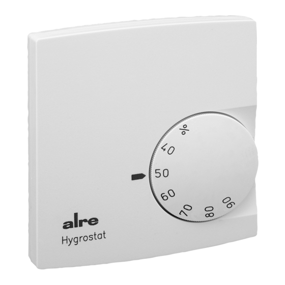
RFHSB - 060.010
– Raumhygrostat Befeuchten / Entfeuchten mit Sollwerteinstellung außen
– Room hygrostat for humidifying / dehumidifying with external set value setting
RFHSB - 060.011
– Raumhygrostat Befeuchten / Entfeuchten mit Sollwerteinstellung innen
– Room hygrostat for humidifying / dehumidifying with internal set value setting
Sicherheitshinweis!
Dieses Gerät darf nur durch eine Elektrofachkraft geöffnet und gemäß dem entsprechenden
Schaltbild im Gehäusedeckel / auf dem Gehäuse / in der Bedienungsanleitung installiert
werden. Dabei sind die bestehenden Sicherheitsvorschriften zu beachten. Nach der Installation
ist der Betreiber, durch die ausführende Installationsfirma, in die Funktion und Bedienung der
Regelung einzuweisen. Die Bedienungsanleitung muss für Bedien- und Wartungspersonal an frei
zugänglicher Stelle aufbewahrt werden.
1. Anwendung
Dieser Regler wurde speziell zur Ansteuerung von Be- und Entfeuchtungsgeräten oder
entsprechenden Klimaanlagen für Hotel-, Wohn- und Geschäftsräume, und anderen Räumen
mit sauberer, nichtaggressiver Umgebung entwickelt. Für andere, vom Hersteller nicht
vorherzusehende Einsatzgebiete, sind die dort gültigen Sicherheitsvorschriften zu beachten.
Eignung hierfür siehe Punkt 8. Gewährleistung.
2. Funktion
Die Geräte verfügen über einen Wechselkontakt der mechanisch durch ein hygroskopisches
Kunststoffband, das auf die Umgebungsfeuchte reagiert, betätigt wird. Der Wechselkontakt darf
im Schaltspannungsbereich von 24 V ~ bis 250 V ~ betrieben werden. Der RFHSB - 060.010
verfügt über einen von außen zugänglichen Einstellknopf. Der RFHSB - 060.011 ist wegen der
Inneneinstellung des Sollwerts besonders für Behörden, Schulen und ähnlich öffentliche Gebäude
geeignet. Lange Standzeiten unter 30 % r.H. kann zum Austrocknen des Kunststoffbandes und
zu Fehlmessungen nach Rückkehr in den Regelbereich führen. Nach Austrocknung benötigt der
Fühler längere Zeit um sich wieder anzugleichen. Es empfiehlt sich in diesen Fall den Regler einer
höheren Umgebungsfeuchte auszusetzen. Eine Betauung ist in jedem Fall zu vermeiden.
3. Installation
Je nach Gerätetyp oder Verpackungsgröße, wird das Gerät entweder geschlossen oder der
schnelleren Montage wegen geöffnet ausgeliefert. Der Regler ist zur Montage auf die Wand oder
UP - Dose bestimmt und darf nicht direkt Wärme- oder Kältequellen ausgesetzt werden. Es ist
darauf zu achten, dass der Regler auch rückseitig keiner Fremderwärmung oder - kühlung,
z.B. bei Hohlwänden durch Zugluft oder Steigleitungen ausgesetzt wird. Vor dem Schließen
des RFHSB - 060.011 wird der gewünschte Sollwert eingestellt. Hierzu befindet sich im
Gehäusedeckel eine gesonderte Anweisungsskizze. Das Öffnen und Schließen erfolgt wie in den
Zeichnungen dargestellt.
Achtung! Bei Verwendung von Spannungen außerhalb des Kleinspannungsbereiches, darf das
Gerät nicht auf leitfähigem Untergrund installiert werden.
3.1 Bereichseinengung des Einstellbereichs
Mittels der Einstellfahnen unter dem Einstellknopf kann der Einstellbereich des RFHSB - 060.010
mechanisch begrenzt werden. Hierzu muss der Knopf abgezogen und nach verstellen der
Anschläge (rot für maximale Feuchte, blau für minimale Feuchte) wieder aufgesteckt werden.
4. Technische Daten
Schaltkontakt:
Wirkungsweise:
Schaltspannung:
Max. zulässiger Schaltstrom:
Befeuchten:
Entfeuchten:
Regelbereich:
Schaltdifferenz:
Fühler:
Elektrischer Anschluss:
Schutzart:
Schutzklasse:
Montage:
Verschmutzungsgrad:
Bemessungsstoßspannung:
Temperatur der Kugeldruckprüfung:
5. Anschlussklemmen
Klemme
Anschlussleitung
1
L, Eingang Schaltspannung
2
Ausgang Befeuchten
3
Ausgang Entfeuchten
Stand 03.2020 (20/024)
potentialfreier Wechselkontakt
Typ 1C
24 V ~ ... 250 V ~, bei 24 V ~ Mindeststrom 100 mA
2 (0,2) A
5 (0,2) A
35 ... 85 % r.H.
ca. 7 % r.H.
hygroskopisches Kunststoffband
Schraubklemmen 0,5 mm² ... 2,5 mm²
IP 30 nach entsprechender Montage
II nach entsprechender Montage
auf Wand oder UP - Dose Ø 55 mm
2
4000 V
75 °C
Safety information!
D
No persons other than expert electricians only must open this device in due compliance with the
wiring diagram shown in the housing cover / on the housing / represented in the corresponding
operating instructions. All expert electricians committed to the execution of any such works must
comply with the relevant safety regulations currently operative and in force. The company charged
with the installation of the device must, after the completion of the installation works, instruct the
user of the control system into its functions and in how to operate it correctly. These operating
instructions must be kept at a place that can be accessed freely by the operating and / or servicing
personnel in charge.
1. Application
This controller has been specially devised for the control and supervision of humidifiers and
dehumidifiers or corresponding air conditioning systems that are used in clean, nonaggressive
ambiances, such as in living spaces, hotel - and office - as well as in other rooms. Regarding other
applications not to be foreseen by the manufacturer of this device, the safety standards these
applications need to be followed and adhered to. Regarding the aptitude of the device for any such
application, please refer to section 8. herein (Warranty).
2. Functional description
The devices dispose of a changeover contact. The actuation of the contact is effected mechanically,
meaning through the operation of a hygroscopic plastic ribbon that reacts to the level of humidity
in the ambient air. The changeover contact is admitted for operation withina switching voltage
range from 24 V ~ up to 250 V ~. The RFHSB - 060.010 has been equipped with an externally
accessible adjusting knob. The RFHSB - 060.011 in contrast, is, owing to the fact that the set
value has to be adjusted internally with this model, particularly suited for the use in office buildings,
schools and other public buildings of similar nature. Longer idle times in ambiances within which
the relative humidity has fallen to below 30 % may lead to the dehydration of the plastic ribbon
and, consequently, to incorrect measuring results after its return to the control range covered by
the device. Once a dehydration of the sensing element occurs, it will take a longer period of time
until the element is again able to converge itself to its former state. It was, in any such case,
recommendable to expose the device to a higher ambient humidity level. The condensation of
moisture must be avoided in any event.
3. Mounting / Installation
The device is, depending on the type version of the device or size of the package used for it,
either delivered in closed or, in order to facilitate its fast installation, also in opened condition. The
controller is determined for installation on an UP box and must not be exposed to any heat or cold
sources whatsoever. Also care must be taken to ensure that it is not exposed to the influence
of heat or cold sources that warm or cool the device at its back (through air flows in cavity walls
or the temperatures radiated by ascending pipelines, f. ex.). The desired set value needs to be
adjusted prior to closing the RFHSB - 060.011. The way in which to do this can be learned from
the separate instruction scheme shown in the housing cover. The opening and closing of the
device takes place as delineated in the related drawings.
Caution: The device must not be installed on a conducting surface when applying any voltages
outside of the low voltage range!
3.1 Delimitation of the setting range
The setting pins located underneath of the adjusting knob enable to delimit the setting range of the
RFHSB - 060.010 mechanically. To enable this, the adjusting knob must be removed by pulling it
off and, after the adjustment of the related pins (red for max. humidity and blue for min. humidity
setting) be put on again in order to lock the limitations.
4. Technical data
Switching contact:
Mode of operation:
Switching voltage:
Max. admissible switching current:
Humidifying:
Dehumidifying:
Control range:
Switching difference:
Sensing element:
Electrical connection:
Degree of protection:
Protection class:
Installation:
Degree of pollution:
Rated impulse voltage:
Temperature of ball indentation test: 75°C
5. Terminals
Terminal
Connecting cable
1
L, switching voltage input
2
output „humidifying"
3
output „dehumidifying"
potential - free changeover contact
Type 1C
24 V ~ ... 250 V ~, (minimum current 24 V ~ 100 mA)
2 (0.2) A
5 (0.2) A
35... 85 % r.h.
approx. 7 % r.h.
hygroscopic plastic ribbon
terminal screws (0.5 mm² ... 2.5 mm²)
IP 30 (after according installation)
II (after according installation)
on the wall or on an UP box Ø 55 mm
2
4000 V
GB
4 12 696 05
Advertisement
Table of Contents

Subscribe to Our Youtube Channel
Related Manuals for alre RFHSB-060.010


Summary of Contents for alre RFHSB-060.010
- Page 1 RFHSB - 060.010 RFHSB - 060.011 RFHSB - 060.010 – Raumhygrostat Befeuchten / Entfeuchten mit Sollwerteinstellung außen – Room hygrostat for humidifying / dehumidifying with external set value setting RFHSB - 060.011 – Raumhygrostat Befeuchten / Entfeuchten mit Sollwerteinstellung innen –...
- Page 2 RFHSB - 060.010 – Hygrostat d’ambiance type humidification / déshumidification avec ajustage de la valeur de consigne externe – Umidificazione / deumidificazione igrostato ambiente con regolazione esterna del valore nominale RFHSB - 060.011 – Hygrostat d’ambiance type humidification / déshumidification avec ajustage de la valeur de consigne interne –...
- Page 3 RFHSB - 060.010 – Pokojový hygrostat Zvlhčení / odvhlčení s vnějším nastavením požadované hodnoty – Higrostat pokojowy nawilżanie/osuszanie z zewnętrzną regulacją wartości zadanej RFHSB - 060.011 – Pokojový hygrostat Zvlhčení / odvhlčení s vnitřním nastavením požadované hodnoty – Higrostat pokojowy nawilżanie/osuszanie z wewnętrzną regulacją wartości zadanej Bezpečnostní...
- Page 4 Kontrola przydatności w zakresie przewidzianym przez zleceniodawcę/ klienta lub do zastosowania w konkretnych warunkach użytkowania jest zadaniem zleceniodawcy/ klienta; nie udzielamy żadnych gwarancji w tym zakresie. Zmiany techniczne zastrzeżone. ALRE-IT Regeltechnik GmbH · Richard-Tauber-Damm 10 · D-12277 Berlin Tel.: +49(0)30/399 84-0 · Fax: +49(0)30/39170 05 · mail@alre.de · www.alre.de...
Need help?
Do you have a question about the RFHSB-060.010 and is the answer not in the manual?
Questions and answers