Advertisement
Quick Links
WARNINGS AND CAUTIONS
•
Read and understand all instructions. Follow all warnings and instructions marked on the product.
•
Do not use this product near water - e.g., near a tub, wash basin, kitchen sink or laundry tub, in a wet
basement, or near a swimming pool.
•
Never push objects of any kind into this product through openings, as they may touch dangerous voltages.
•
SAVE THESE INSTRUCTIONS.
DESCRIPTION
The Model 45A00-1 Supervised Wireless Receiver allows up to 64 unique wireless security transmitters to report
information to an Leviton controller. The wireless transmitters replace wired door and window sensors, as well as
wired smoke, motion, glassbreak detectors, and handheld keyfobs. These transmitters report status information
to the 45A00-1 Receiver which, in turn, processes the information and reports it to the Leviton controller.
COMPATIBLE TRANSMITTERS
The Model 45A00-1 Supervised Wireless Receiver is compatible with Leviton Wireless Transmitters.
These transmitters include the 46A00-1 Door/Window Transmitter,
47A00-1 Quad Pet Immune Motion Detector, 48A00-1 4 Button Keyfob, 49A00-1 Smoke and Carbon
Monoxide Detector, and 50A00-1 Panic/Alert Pendant.
INSTALLATION
Install the receiver in a central area of the premises, as high above
ground as practical. The receiver may be mounted up to 1000 feet
from the Leviton controller.
•
The receiver should be at least 5 feet from the controller or any
other electronic device.
•
Avoid areas where receiver will be exposed to moisture.
•
Avoid areas with excessive metal or electrical wiring. If unavoidable,
mount where antenna extends above a metallic surface.
When the location of the receiver has been established:
1. Position the supplied Mounting Base so that the Mounting Base
Latch is at the top. Hold the Mounting Base against the mounting
surface (allow at least a 6-inch clearance above the Mounting
Base) and secure it using the supplied screws (see Figure 1).
2. Align the notches on the back of the Wireless Receiver case with the
tabs on the Mounting Base. Make sure the tabs are fully inserted into
the notches and push downward to latch.
SPECIFICATIONS
Dimensions:
2.5W x 3.75H x 1.0D, excluding antenna
Current Consumption:
30mA maximum
Operating Temperature: 32o F - 140o F (0 o C - 60o C)
Maximum Humidity:
90% relative humidity, non-condensing
OPERATION
The two operating modes of the receiver are "Run" and "Setup".
In Run Mode, with the receiver connected to and communicating with the
controller, the Mode LED (see Figure 2) should blink once per second. The
receiver monitors the status of each transmitter. If the status condition of
a transmitter changes, it is reported to the receiver and the information is
updated on the LED display and the Status LED will flash.
The transmitter number flashes on the display and the Status LED flashes
whenever a report is received from a transmitter. The display will continually
display the status of any transmitters that are violated (not ready) or that
have trouble. The transmitter number flashes on the display followed by the
status condition(s).
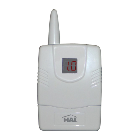
LED DISPLAY
INFORMATION ABOUT THE LED DISPLAY
1.1
Displays the number of the transmitter with a change in condition.
A L
Displays that the current transmitter is "NOT READY".
C O
Displays that the cover was removed from the current transmitter.
S F
Displays that the current transmitter has a supervision failure.
L O
Displays that the current transmitter has reported a battery low.
NOTE: If the receiver is not communicating with the controller, the Mode LED will blink four times per second.
SET - The Set switch (see Figure 2) is used to increment or change the current selection.
MODE /ADVANCE - The Mode/Advance switch (see Figure 2) is used to enter Setup Mode, advance to the next
Setup item, and to confirm a selection. It is also used to exit Setup Mode.
LED DISPLAY - The LED Display (see Figure 2) is used to show the status of each transmitter and to ensure proper
setup.
MODE LED - In Run Mode, the Mode LED (see Figure 2) is used to indicate communication status with the controller.
In Setup Mode, the Mode LED is used to indicate if a transmitter sends a restore code.
TYPE LED - In Setup Mode, the Type LED (see Figure 2) is used to indicate if a transmitter is supervised.
SETUP MODE - The Setup Mode is used to configure the general operating parameters of the receiver, to program a
transmitter into the receiver, and to change the characteristics of a programmed transmitter. The Mode LED does not
blink in Setup Mode.
To enter the Setup Mode:
A. Press and hold the Mode/Advance switch for approximately two seconds.
B. Press the Set switch to increment the value of a Setup item.
C. Press the Mode/Advance switch is to advance to the next Setup item.
FOR CANADA ONLY
For warranty information and/or product returns, residents of Canada should contact Leviton in writing at Leviton Manufacturing of Canada Ltd to the attention of the Quality Assurance Department, 165 Hymus Blvd, Pointe-Claire (Quebec), Canada H9R 1E9 or by telephone at 1 800 405-5320.
Leviton warrants to the original consumer purchaser and not for the benefit of anyone else that products manufactured by Leviton under the Leviton brand name ("Product") will be free from defects
in material and workmanship for the time periods indicated below, whichever is shorter: • OmniPro II and Lumina Pro: three (3) years from installation or 42 months from manufacture date.
• OmniLT, Omni IIe, and Lumina: two (2) years from installation or 30 months from manufacture date. • Thermostats, Accessories: two (2) years from installation or 30 months from manufacture date.
• Batteries: Rechargeable batteries in products are warranted for ninety (90) days from date of purchase. Note: Primary (non-rechargeable) batteries shipped in products are not warranted.
Products with Windows
®
Operating Systems: During the warranty period, Leviton will restore corrupted operating systems to factory default at no charge, provided that the product has been
used as originally intended. Installation of non-Leviton software or modification of the operating system voids this warranty. Leviton's obligation under this Limited Warranty is limited to the repair or
replacement, at Leviton's option, of Product that fails due to defect in material or workmanship. Leviton reserves the right to replace product under this Limited Warranty with new or remanufactured product.
Leviton will not be responsible for labor costs of removal or reinstallation of Product. The repaired or replaced product is then warranted under the terms of this Limited Warranty for the remainder
of the Limited Warranty time period or ninety (90) days, whichever is longer. This Limited Warranty does not cover PC-based software products. Leviton is not responsible for conditions or applications
beyond Leviton's control. Leviton is not responsible for issues related to improper installation, including failure to follow written Installation and operation instructions, normal wear
and tear, catastrophe, fault or negligence of the user or other problems external to the Product. To view complete warranty and instructions for returning product, please visit us at www.leviton.com.
Use herein of third party trademarks, service marks, trade names, brand names and/or product names are for informational purposes only, are/may be the trademarks of their
respective owners; such use is not meant to imply affiliation, sponsorship, or endorsement.
© 2013 Leviton Mfg. Co., Inc.
WIRELESS 64 ZONE RECEIVER
CAT. NO. 45A00-1
Installation Instructions and User's Guide
INSTALLATION
WARNINGS AND CAUTIONS
•
•
•
•
Receiver Address
You are first prompted to enter the receiver address. "A" is shown on the left of the display and the current address
is shown on the right. Press the Set switch to increment the address value. The current address will be stored into
memory when the Mode/Advance switch is pressed. Setup Mode is exited when the Mode/Advance switch is pressed
and held for two seconds.
Number of Addresses
Next, you are prompted to enter the "number of addresses" (see the Setup information in this document for
configuration of each controller). The letter "n" is shown on the left of the display and the digit for the current number
of addresses is shown on the right of the display. Press the Set switch to increment the number of addresses value.
The current number of addresses will be stored into memory when the Mode/Advance switch is pressed. Setup Mode
MOUNTING
is exited when the Mode/Advance switch is pressed and held for two seconds.
BASE LATCH
Configuring Transmitters
All of the following locations are used for configuring and programming transmitters. Each new transmitter can be
programmed into the receiver and each programmed transmitter, along with its characteristics, is displayed and can
MOUNTING HOLE
be modified. The transmitter number is shown in the LED Display. If no transmitter is programmed in an address
TAB
location, neither the Mode LED nor the Type LED will be lit. If a transmitter is programmed in an address location:
1. The Mode LED indicates whether the transmitter sends restore transmissions.
MOUNTING
BASE
2. The Type LED shows whether the transmitter is supervised.
TAB
The Set switch is used to change the characteristics of a programmed transmitter. Each press of the Set switch cycles
MOUNTING HOLE
through each combination of supervised, sends restores, or no transmitter programmed.
The Mode/Advance switch is used to advance to the next transmitter address location. Setup Mode is exited by
ANTENNA
pressing and holding the Mode/Advance switch for two seconds.
TEACHING THE RECEIVER A TRANSMITTER ADDRESS
If no transmitter is programmed in an address location, a new transmitter may be programmed into that address
MODE
location by activating the desired transmitter. The activated transmitter will then be entered into that address location.
LED
The transmitter must be activated according to the instructions that accompany the transmitter.
Based on the type of transmitter, the receiver will try to set the supervisory and restore characteristics that are
TYPE
LED
LED
appropriate for that type of transmitter. These can be changed as desired using the Set switch.
DISPLAY
Once a transmitter is programmed into an address location, the transmitter address will briefly turn off whenever
a transmission from that transmitter is received. This can be used to verify that the correct transmitter has been
programmed and is operating reliably.
NOTE: The controller ignores the current status of each transmitter while the receiver is in Setup Mode.
TRANSMITTER SETUP
1. Press and hold the Mode/Advance button for two (2) seconds.
2. "A1" will appear. On OmniLT, Omni II, and Lumina "A1" is always used. On OmniPro II and Lumina Pro the
MODE
SET
3. Press the Mode/Advance button to save any changes and proceed.
4. Next, "n1" will appear. The value of "n" will determine the number of addresses used.
D3
+12V
A
B GND
5. Press the Mode/Advance button to save any changes and proceed.
SET
6. "1" will appear (1st transmitter address location). Trip the transmitter. When the 45A00-1 receives the
SWITCH
MODE/ADVANCE
SWITCH
7. Press the Mode/Advance button to save the changes and proceed.
8. "2" will appear (2nd transmitter address location). Trip the transmitter. When the 45A00-1 receives the
9. Press the Mode/Advance button to save the changes and proceed.
10. Repeat for each transmitter address (1-64) until all transmitters have been programmed.
11. After all transmitters have been programmed, replace the cover.
RESETTING OR REMOVING A TRANSMITTER
To replace an existing transmitter, reset the characteristics of a transmitter, or remove a transmitter, enter Setup Mode
as described under "Transmitter Setup" in this manual. When the transmitter address location appears on the display,
remove the transmitter's characteristics by pressing the SET button until there are no dots (blinking or otherwise) on
either side of the address number. The transmitter in now removed. To replace the transmitter, simply trip the new
transmitter. When the 45A00-1 receives the transmission, the 45A00-1 will display the digit (transmitter address
location) with a dot on either side (the dots indicate the transmitter's characteristics).
RESET MEMORY
To erase all transmitters from memory and to reset to the factory default configuration, press and hold both the Set
and Mode/Advance switches simultaneously for 2 seconds. The display will show "EE". If you choose to continue,
press and hold the Set and Mode/Advance switches simultaneously for 2 seconds once again. Memory is reset at the
end of the two seconds.
NOTE: If you choose not to reset memory at the "EE" display, don't press any keys for 10 seconds and the receiver
will return to Run Mode.
CONNECTING TO OMNILT
Connect the receiver to the OmniLT controller using 4-conductor, 22-gauge or larger wire as follows:
1. Connect the "A" and "B" terminals of the 45A00-1 to the "YEL" (Yellow) and "GRN" (Green) terminals under the
2. Connect the "+12" and "GND" terminals of the 45A00-1 to the "RED" and "BLK" (Black) terminals under the
LEVITON LIMITED WARRANTY
For Technical Assistance Call: 800-824-3005 - www.leviton.com
Never install communications wiring or components during a lightning storm.
Never install communications components in wet locations unless the components are designed
specifically for use in wet locations.
Never touch uninsulated wires or terminals unless the wiring has been disconnected at the network interface.
Use caution when installing or modifying communications wiring or components.
•
The Mode LED is on if the transmitter sends restore transmissions, and off if it doesn't.
•
The Type LED is on steady if the transmitter is supervised, and blinks if it isn't.
address will depend on the number of expansion enclosures used (see "OmniPro II / Lumina Pro Setup" for more
information).
transmission, the 45A00-1 will display the digit (transmitter address) with a dot on either side (the dots indicate the
transmitter's characteristics).
transmission, the 45A00-1 will display the digit (transmitter address) with a dot on either side (the dots indicate the
transmitter's characteristics).
section marked "CONSOLE" on the OmniLT controller (Yellow = A and Green = B).
section marked "CONSOLE" on the OmniLT controller (Red = +12V and Black = GND).
DI-021-SY450-05A
AR2243
(45I00-1)
ENGLISH
DI-021-SY450-05A
AR2243
Advertisement

Subscribe to Our Youtube Channel
Related Manuals for Leviton 45A00-1


Summary of Contents for Leviton 45A00-1
- Page 1 For warranty information and/or product returns, residents of Canada should contact Leviton in writing at Leviton Manufacturing of Canada Ltd to the attention of the Quality Assurance Department, 165 Hymus Blvd, Pointe-Claire (Quebec), Canada H9R 1E9 or by telephone at 1 800 405-5320.
- Page 2 B. When connected to Omni II / Lumina, Zones 33-48 are the wireless receiver zones. C. When connected to Omni II / Lumina, the receiver address on the 45A00-1 must be set to “A1” and the To enter Setup Mode, press and hold the Mode/Advance switch for 2 seconds.
Need help?
Do you have a question about the 45A00-1 and is the answer not in the manual?
Questions and answers