Table of Contents
Advertisement
Quick Links
Advertisement
Table of Contents

Related Manuals for Flashcut CNC 401A

Summary of Contents for Flashcut CNC 401A
- Page 1 Computer Numerical Control for Windows Model 401A Motor Signal Generator Hardware Guide LIMIT RXD TXD POWER © 1998 FlashCut CNC, Inc. 1263 El Camino Real, Suite W, Menlo Park, CA 94025 Phone (650) 853-1444 • Fax (650) 853-1405 • www.flashcutcnc.com...
-
Page 3: Table Of Contents
Table of Contents GETTING STARTED............................1 ............................1 BOUT THIS ANUAL ..............................2 YSTEM AFETY HARDWARE GUIDE............................3 ....................3 VERVIEW OF OTOR IGNAL ENERATOR ..............................3 RONT ANEL ............................... 3 ANEL .......................... 6 URNING OFF THE ONTROLLER... -
Page 5: Getting Started
Getting Started Section About this Manual FlashCut CNC is a unique application involving both hardware and software, so you’ll need some instruction to get started. Since automated machining is potentially dangerous, please take the time to completely read through this manual and the Software User’s Guide to understand the operation of the electronics,... -
Page 6: System Safety
Getting Started System Safety When running any machining operation, safety is of utmost importance. For proper and safe use of the FlashCut CNC program and your CNC machine, the following safety guidelines must be followed: Never let the machine run unattended. -
Page 7: Hardware Guide
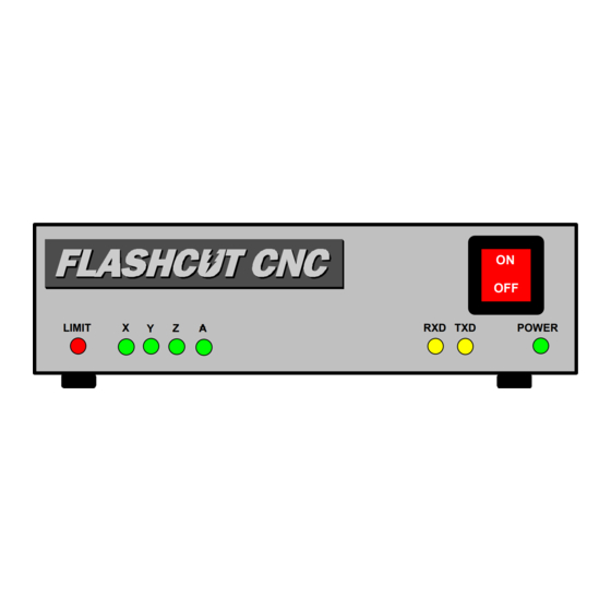
Power - Turns green when the power switch is turned on. On/Off Switch - Turns the unit on and off. If there is ever a communications error while running FlashCut CNC, turn the switch off and on to reset the internal microprocessor. - Page 8 When a switch is open, its input signal is high (+5V). When the switch is closed, its input signal is grounded low (0V). The 401A is wired for normally closed (NC) switches. Each line that is not connected to a switch must be wired directly to its ground. When any of the input lines are open the red limit light will illuminate and a signal will be sent to the host PC to indicate which input line(s) went high.
- Page 9 MOTOR SIGNALS - The DB-25 male connector for all signals going out to the stepper motor driver(s). If you are using one of the FlashCut CNC stepper motor drivers, connect this to the DB-25 female connector on the stepper motor driver using a DB25 M-F interface cable.
-
Page 10: Turning Off The Controller
FlashCut CNC FlashCut CNC Section Section 2 2 Hardware Guide Hardware Guide BE VERY CAREFUL WHEN DOING ANY WIRING. IMPROPER WIRING WILL DAMAGE THE MOTOR SIGNAL GENERATOR. Two pins are directly connected to ground and +5V from the internal power supply. These are provided for convenience as a source for the optical ground and optical +5V if there is no external power source available.
Need help?
Do you have a question about the 401A and is the answer not in the manual?
Questions and answers