Table of Contents
Advertisement
Quick Links
™
Control Made Simple
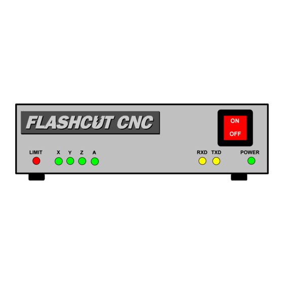
Model 401A
Signal Generator
Hardware Guide
ON
OFF
LIMIT
1
2
3
4
RXD TXD
POWER
West Coast Office
Midwest Office
1263 El Camino Real
444 Lake Cook Road, Suite 17
Menlo Park, CA 94025
Deerfield, IL 60015
Phone (650) 853-1444 ♦ Fax (650) 853-1405
Phone (847) 940-9305 ♦ Fax (847) 940-9315
www.flashcutcnc.com
www.flashcutcnc.com
Revised 5-28-03
© 1998-2003 FlashCut CNC, Inc.
Advertisement
Table of Contents

Related Manuals for Flashcut CNC 401A


Summary of Contents for Flashcut CNC 401A
- Page 1 1263 El Camino Real 444 Lake Cook Road, Suite 17 Menlo Park, CA 94025 Deerfield, IL 60015 Phone (650) 853-1444 ♦ Fax (650) 853-1405 Phone (847) 940-9305 ♦ Fax (847) 940-9315 www.flashcutcnc.com www.flashcutcnc.com Revised 5-28-03 © 1998-2003 FlashCut CNC, Inc.
-
Page 3: Table Of Contents
Table of Contents GETTING STARTED ............................1 ..............................1 BOUT THIS ANUAL ..........................2 AFETY AND SAGE UIDELINES HARDWARE GUIDE ............................3 ........................3 VERVIEW OF THE IGNAL ENERATOR ................................3 RONT ANEL ................................3 ANEL ..............................7 UMPER ETTINGS JP2 .................................7 JP3..................................8 JP4, JP5 &... -
Page 5: Getting Started
Section Getting Started About this Manual FlashCut CNC is a unique application involving hardware and software, so you’ll need some instruction to get started. Since automated machining is potentially dangerous, please take the time to completely read through this manual and the software User’s Guide to understand the operation of the electronics,... -
Page 6: Safety And Usage Guidelines
Safety and Usage Guidelines When running an automated machine tool, safety is of utmost importance. For proper and safe use of the FlashCut CNC program and your CNC machine, the following safety guidelines must be followed: 1. Never let the machine tool run unattended. -
Page 7: Hardware Guide
The Signal Generator provides a flexible interface that controls up to 4 stepper or digital servo motor drivers, 8 output lines and 8 input lines. It works in conjunction with the FlashCut CNC software. Please note that there are several software and hardware settings that affect the use of the Signal Generator. These settings are described in this manual and in the software User’s Guide. - Page 8 (+5V). When the switch is closed, its input signal is grounded low (0V). The 401A is wired for all normally closed (NC) or all normally open (NO) switches. When in NC mode, each line that is not connected to a switch must be wired directly to its ground.
- Page 9 FlashCut CNC Section 2 Hardware Guide The input lines are all optically isolated. This means that a 5V power source must be provided to power the external end of the optical couplers. There are two ways to do this listed below. Note that you must use only one of the two options below.
- Page 10 MOTOR SIGNALS – The DB-25 male connector for all signals going out to the stepper or digital servo motor driver(s). If you are using one of the FlashCut CNC motor drivers, connect this to the DB-25 female connector on the motor driver using a DB25 M-F interface cable.
-
Page 11: Jumper Settings
FlashCut CNC Section 2 Hardware Guide Two input pins are provided for optical ground (pin 25) and optical VCC (pin 23) to power the optical couplers on the input lines (see above). You can place a 5 VDC power source across these two pins. If you are powering input lines internally using JP1 and JP2, do not connect these input pins. -
Page 12: Jp3
If you are not using any limit switches, you should set JP3 to NO mode (shorted). If you are using the FlashCut CNC Limit Switch Kit, you should set JP3 to NC mode (open). JP4, JP5 & JP6 These switches are for FlashCut CNC Personnel use only and should always be open. -
Page 13: Sample Wiring Diagrams
FlashCut CNC Section 3 Sample Wiring Diagrams Section Sample Wiring Diagrams... -
Page 14: Typical Motor Signal Circuit For Half-Stepping And Microstepping Drives
FlashCut CNC Section 3 Sample Wiring Diagrams Typical Motor Signal Circuit For Half-Stepping and Microstepping Drives Signal Generator Model 401 A STEP VDC+ 32VDC VDC- DB25-22 74LS32N The above schematic shows a typical connection of a single axis motor driver to the motor signals of the Signal Generator. -
Page 15: Typical Motor Signal Circuit Ii
FlashCut CNC Section 3 Sample Wiring Diagrams Typical Motor Signal Circuit II Signal Generator Model 401 A Step Clock Phase A CW/CCW Phase A~ Enable Phase B~ Half/Full Phase B Logic Ground 40VDC Ground Current Adjust 2KΩ DB25-24 74LS32N The above schematic shows a typical connection of a single axis motor driver to the motor signals of the Signal Generator. -
Page 16: Motor Signal Circuit For Gecko Drives
FlashCut CNC Section 3 Sample Wiring Diagrams Motor Signal Circuit For Gecko Drives Signal Generator Model 401 A STEP Phase A Phase B DISABLE Phase C Phase D COMMON 40VDC Ground DB25-22 74LS32N The above schematic shows a typical connection of a single axis motor driver to the motor signals of the Signal Generator. -
Page 17: Typical Output Line Circuit
FlashCut CNC Section 3 Sample Wiring Diagrams Typical Output Line Circuit Load Signal Generator Model 401 A Output1 AC Power Fuse Solid State Relay Continental Industries S505-0SJ610-000 The above schematic shows a typical connection of one solid state relay controlled by output line 1 of the Signal Generator. -
Page 18: Typical Input Line Circuit
23 and 25 of the DB25 Motor Signal connector. Input lines 1-4 and 5- 8 are internally connected to pins 15-18 and 5-8 respectively of the DB25 Motor Signal connector. Note that the FlashCut CNC limit switch kit has the same wiring as shown in this example. -
Page 19: I/O Connector And Header Schematic
FlashCut CNC Section 3 Sample Wiring Diagrams I/O Connector and Header Schematic... -
Page 20: Signal Generator Board Layout
FlashCut CNC Section 3 Sample Wiring Diagrams Signal Generator Board Layout... - Page 21 FlashCut CNC Section 3 Sample Wiring Diagrams...
Need help?
Do you have a question about the 401A and is the answer not in the manual?
Questions and answers