Advertisement
Advertisement

Subscribe to Our Youtube Channel
Related Manuals for SainSmart Genmitsu 3018-MX3


Summary of Contents for SainSmart Genmitsu 3018-MX3
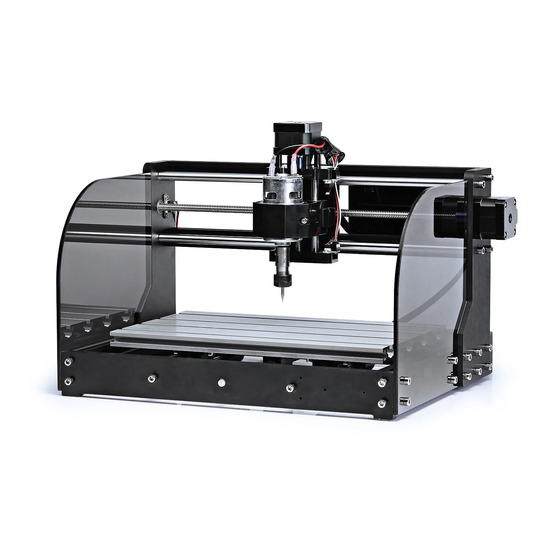
- Page 1 Genmitsu CNC Router 3018-MX3 USER MANUAL V1.1 Jun 2020...
-
Page 2: Table Of Contents
Contents ......................... Part 1: Package List ..................... Part 2: Mechanical installation ................Part 3: 3018 MX3 Control Card Introduction ....................... Part 4: Installation the Mach3 ................... Part 5: Engraving process example ............... Part 6: How to release the limit switch trigger ................ -
Page 3: Part 1: Package List
Part 1: Package List TYPE NAME SIZE/PARAMETERS PICTURES QTY. 20 x 40 x 290mm MX3-1 Aluminum Profile 20 x 20 x 360mm MX3-2 Aluminum 180 x 300mm MX3-3 Workbench Mechanical Part Guide Rail Ø10 x 360mm MX3-4 (X Axis) Guide Rail Ø10 x 290mm MX3-5 (Y Axis) - Page 4 TYPE NAME SIZE/PARAMETERS PICTURES QTY. Phenolic resin plate-R 90 x 220mm MX3-8 (X Axis) Phenolic resin plate-L 90 x 220mm MX3-9 (X Axis) Phenolic resin plate-F 46 x 360mm MX3-10 Mechanical (Y Axis) Part Phenolic resin plate-B 46 x 360mm MX3-11 (Y Axis) X-Z Axis...
- Page 5 TYPE NAME SIZE/PARAMETERS PICTURES QTY. 42 Stepper NEMA17 34mm MX3-13 motor Spindle 775-ER11 MX3-14 ER11 Collet ER11-3.175 MX3-15 Coupling 5mm-8mm MX3-16 Mechanical T-Copper Nut MX3-17 Part Spring 12 x 30 mm MX3-18 Bearing mount MX3-19 (Y Axis) Nut mount MX3-20 (Y Axis) Acrylic protection...
- Page 6 TYPE NAME SIZE/PARAMETERS PICTURES QTY. Control Board NEMA17 34mm MX3-22 MC3D3 Insulated MX3-23 Board USB cable MX3-24 Electrical Part 24V power 24V 5A MX3-25 supply Power cable 1.2M MX3-26 (US) Power cable 1.2M MX3-27 (EU) Limit Switch MX3-28...
- Page 7 TYPE NAME SIZE/PARAMETERS PICTURES QTY. X LIM+ 15cm MX3-29 X LIM- 53cm MX3-30 Limit Switch Y LIM+ 30cm MX3-31 Connecting Y LIM- 60cm MX3-32 wire Z LIM+ 34cm MX3-33 Mechanical Z LIM- 40cm MX3-34 Part X Axis 17cm MX3-35 Stepper motor Y Axis 52cm MX3-36 Connecting...
- Page 8 TYPE NAME SIZE/PARAMETERS PICTURES QTY. Work fixture MX3-39 Probe Tool MX3-40 Tools/ Engraving accessories NJ3.2001 MX3-41 Knife 2.0mm, 2.5mm, 3.0mm, Allen wrench MX3-42 4.0mm, 5.0mm Open end 17 x 108mm MX3-43 wrench 13 x 87mm MX3-44 Screwdriver Cable tie 3 x 80mm MX3-45...
- Page 9 TYPE NAME SIZE/PARAMETERS PICTURES QTY. Wire holder MX3-46 Sealing strip 270mm MX3-47 (Y Axis) Sealing strip 340mm MX3-48 (X Axis) Tools/ Nylon braided 200mm MX3-49 accessories tube Memory card MX3-50 with reader Manual book MX3-51...
- Page 10 TYPE NAME SIZE/PARAMETERS PICTURES QTY. M3 bolt M3 x 14mm MX3-52 M5 x 10mm MX3-53 M5 x 14mm MX3-54 M5 bolt M5 x 16mm MX3-55 M5 x 20mm MX3-56 M6 bolt M6 x 16mm MX3-57 M3 x 20mm MX3-58 M3 screw Screw/Nut M3 x 6mm MX3-59...
-
Page 11: Part 2: Mechanical Installation
Part 2: Mechanical installation Step 1: Stepper motor Assembly Installation NAME CODE QTY. BEFORE MX3-13 x 2Pcs 42 Stepper Motor MX3-13 flat Prepare materials Coupling MX3-16 MX3-16 x 2Pcs Tools Allen wrench (2mm) AFTER Load the hole of φ5mm part of the coupling, fix into the Operation Axis of motor, must lock the screws on the flat of the Steps... - Page 12 Step 2: Install Phenolic resin plate-R (X Axis) NAME CODE QTY. BEFORE Phenolic resin plate-R (X Axis) MX3-8 MX3-58 x 2Pcs MX3-59 x 4Pcs Stepper motor Assembly (from Step1) MX3-28 MX3-63 Bolt M3 x 14mm MX3-52 x 2Pcs Limit switch MX3-28 Prepare materials...
- Page 13 Step 3: Install Phenolic resin plate-L (X Axis) NAME CODE QTY. BEFORE Phenolic resin plate-L (X Axis) MX3-9 MX3-28 MX3-59 x 2Pcs MX3-9 Prepare Limit switch MX3-28 materials M3 ScrewM3 x 6mm MX3-59 Tools Screwdriver AFTER Operation Steps Check Make sure the right direction of the limit switch. Remind...
- Page 14 Step 4: Install Phenolic resin plate-B/F (Y Axis) NAME CODE QTY. BEFORE Phenolic resin plate-B (Y Axis) MX3-11 MX3-28 x 2Pcs MX3-11 Phenolic resin plate-F (Y Axis) MX3-10 Prepare MX3-59 x 10Pcs M3 Screw M3 x 6mm MX3-59 materials Limit switch MX3-28 MX3-10 MX3-46 x 6Pcs...
- Page 15 Step 5: Base Installation NAME CODE QTY. BEFORE Aluminum Profile 20 x 40 MX3-1 MX3-11 Phenolic resin plate-F (from Step4) MX3-1 x 2Pcs Prepare MX3-10 materials MX3-56 x 8Pcs Phenolic resin plate-B (from Step4) M5 Bolt M5 x 20mm MX3-56 Tools Allen wrench (4mm) AFTER...
- Page 16 Step 6: Install (Y Axis) Bearing mount (Y Axis) NAME CODE QTY. BEFORE Guide Rail (Y Axis) MX3-5 MX3-5 x 2Pcs Bearing mount (Y Axis) MX3-19 Prepare materials Base (from Step5) MX3-55 x 4Pcs M5 Bolt M5 x 16mm MX3-56 MX3-19 x 4Pcs Tools Allen wrench (4mm)
- Page 17 Step 7: Install Lead Screw Assembly (Y Axis) NAME CODE QTY. BEFORE Lead Screw 297mm (Y Axis) MX3-7 MX3-18 MX3-7 T-Copper Nut MX3-17 MX3-17 Prepare materials Spring MX3-18 13mm MX3-20 Nut mount (Y Axis) MX3-20 Tools AFTER Make the T-Copper rotate to the Lead Screw, pay attention to the distance between the nut and Lead Screw for 13mm.
- Page 18 Step 8: Running part (Y Axis) Installation NAME CODE QTY. BEFORE Stepper motor Assembly (from Step1) MX3-13 M3 Bolt M3 x 14mm MX3-52 Prepare materials Base (from Step6) MX3-52 x 4Pcs Lead Screw assembly (from Step7) Tools Allen wrench (2mm, 2.5mm, 4mm) AFTER Put the Lead Screw assembly into The Base, insert the end of the Phenolic...
- Page 19 Step 9: Aluminum Nuts Installation NAME CODE QTY. BEFORE Nut 30 x M6 MX3-61 MX3-61 x 10Pcs Prepare materials MX3-57 x 10Pcs M6 Bolt M6 x 16mm MX3-57 Allen wrench (5mm) Tools AFTER Operation Using the Allen wrench turn the screw just 20% into the nut.
- Page 20 Step 10: Aluminum Workbench Installation NAME CODE QTY. BEFORE MX3-3 Aluminum Workbench MX3-3 Prepare materials Base (from Step 9) Allen wrench (5mm) & Open end wrenchs AFTER Tools Turn over the Base in the side of the Aluminum workbench, move the base and make sure the nuts insert into the three channels of the workbench.
- Page 21 Step 11: Prepare Phenolic resin plate-R/L NAME CODE QTY. BEFORE (X Axis) Phenolic resin plate-R (from Step2) (X Axis) Phenolic resin plate-L (from Step3) Prepare MX3-60 MX3-55 x 12Pcs x 12Pcs materials Nut 20 x M5 MX3-60 M5 Bolt M5 x 16mm MX3-55 Tools AFTER...
- Page 22 Step 12: Install Phenolic resin plate-R/L NAME CODE QTY. BEFORE Phenolic resin plate-R (from Step 11) Prepare Phenolic resin plate-L (from Step 11) materials Base (from Step 11) Tools Allen wrench (4mm) AFTER Fix the Phenolic resin plates on the base, Use the Allen Operation wrench tighten the Bolts 80% in advance, remain 20% Steps...
- Page 23 Step 13: Install X-Z Axis Assembly & Guide Rail NAME CODE QTY. BEFORE MX3-55 x4Pcs X-Z Axis Assembly MX3-12 Prepare M5 Bolt M5 x 20mm MX3-55 materials MX3-12 MX3-4 x2Pcs Guide Rail (X Axis) Tools Allen wrench (4mm) AFTER Make the Phenolic resin plates mismatch, First insert the Operation guide rail to the holes and tighten the Bolt 20% in one Steps...
- Page 24 Step 14: Aluminum Profile (X Axis) Installation NAME CODE QTY. BEFORE MX3-2 Aluminum Profile 20 x 20 MX3-56 x 4Pcs Prepare MX3-2 M5 Bolt M5 x 20mm MX3-56 x 2Pcs materials Base (from Step 13) Tools Allen wrench (4mm) AFTER Fix the Aluminum Profile on the Phenolic resin plate, Operation Use the Allen wrench tighten all the Bolts 80% in advance,...
- Page 25 Step 15: Prepare Lead Screw Assembly (X Axis) NAME CODE QTY. BEFORE Lead Screw (X Axis) 365mm MX3-6 Phenolic resin plate-L MX3-17 Prepare T-Copper Nut MX3-17 materials 33~38mm MX3-6 MX3-18 Spring MX3-18 Tools AFTER First, insert the Lead Screw into the Phenolic resin plate-L, then make the T-Copper rotate to the Lead Operation Screw, pay attention to the distance between the nut...
- Page 26 Step 16: Install Lead Screw Assembly (X Axis) NAME CODE QTY. BEFORE Lead Screw Assembly Prepare Lead Screw Assembly (from Step15) materials Tools Allen wrench (2mm) AFTER Insert the Lead Screw assembly to the X-Z Axis Assembly, then rotate the Lead Screw into the nut inside of the X-Z Axis assembly.
- Page 27 Step 17: Install Spindle NAME CODE QTY. BEFORE MX3-14 Prepare Spindle MX3-14 M4 Bolt materials Tighten the screw Tools AFTER Allen wrench (3mm) Loosen the M4 bolt in the X-Z Axis assembly, Vertical place the spindle to the ring of the X-Z Axis assembly. Operation When the gray cover of the spindle complete fall into the Steps...
- Page 28 Step 18: Install Control board Assembly NAME CODE QTY. BEFORE MX3-60 MX3-62 Control board MC3D3 MX3-22 MX3-22 x 4Pcs x 4Pcs Insulated Board MX3-23 Prepare M5 Bolt M5 x 14mm MX3-54 materials Nut20 x M5 MX3-60 ABS spacer MX3-62 MX3-23 MX3-54 x 4Pcs Tools Allen wrench (4mm)
- Page 29 Step 19: Install Acrylic protection board NAME CODE QTY. BEFORE Acrylic protection board MX3-21 MX3-53 MX3-21 x x 8Pcs 2Pcs Prepare MX3-29 M5 Bolt M5 x 10mm MX3-53 materials Nut 20 x M5 MX3-60 MX3-60 x 8Pcs Tools Allen wrench(4 mm) AFTER Use the Allen key to turn the screw into the nut for 20% only...
- Page 30 Step 20: Wiring Connecting wires ( X Axis Limit Switch) NAME CODE QTY. BEFORE Limit Switch Connecting wire MX3-29 X LIM + 15cm MX3-30 MX3-29 Prepare Limit Switch Connecting wire MX3-30 materials X LIM - 53cm Sealing strip 340mm (X Axis) MX3-48 Tools AFTER...
- Page 31 Step 21: Wiring Connecting wires (Y Axis Limit Switch) NAME CODE QTY. BEFORE Limit Switch Connecting wire MX3-31 Y LIM + 30cm Prepare Limit Switch Connecting wire MX3-32 MX3-32 materials Y LIM - 60cm MX3-31 MX3-47 Sealing strip 270mm (Y Axis) MX3-47 use here Tools...
- Page 32 Step 22: Wiring Connecting wires (Z Axis Limit Switch) NAME CODE QTY. BEFORE MX3-33 Limit Switch Connecting wire MX3-33 Z LIM + 34cm Prepare MX3-34 materials Limit Switch Connecting wire MX3-34 Z LIM - 40cm Tools AFTER Operation Put Limit switch connecting wire insert the Control board Steps and Limit switch, the switch near by the motor is the LIM+.
- Page 33 Step 23: Wiring Connecting wires (Stepper motors) NAME CODE QTY. BEFORE MX3-37 (X Axis) Stepper motor connecting MX3-35 wire 17cm Prepare (Y Axis) Stepper motor connecting MX3-36 MX3-35 materials wire 52cm (Z Axis) Stepper motor connecting MX3-37 MX3-36 wire 28cm Tools AFTER Operation...
- Page 34 Step 24: Wiring Spindle motor wires NAME CODE QTY. BEFORE MX3-38 Prepare Spindle motor wires 35cm MX3-38 materials Tools AFTER Operation Use the spindle motor wire insert the Control board, Steps NOTE: Red wire to M +, Black wire to M - Pay attention the mark on the Control board, make sure Check the correct sequence and direction of the connectors.
- Page 35 Step 25: Sorting wires & Prepare Commissioning NAME CODE QTY. BEFORE Cable tie (Black) MX3-45 MX3-49 use here Prepare materials MX3-45 use here Nylon braided tube MX3-49 Lubricating oil ( provide by yourself ) Tools AFTER Use cable tie to fix all the wires which across the wire Operation holder.
-
Page 36: Part 3: 3018 Mx3 Control Card Introduction
Part 3: Control Card Introduction a. Connection diagram a. Connection diagram X Axis Y Axis Z Axis Spindle motor motor motor 12V power + PWM signal for laser power module PWM signal output USB connection Laser module X Y Z axis limit/home switch ESTOP / Z Zero Tool... - Page 37 b. 3018 MX3 control card features 1. Applicable to mach3mill CNC software, support Windows XP, Windows 7 32 / 64bit, Windows8, Windows10 operating system; 2. USB interface communication, support 3-axis engraving, support laser cutting; 3. Support automatic tool setting function; 4.
- Page 38 c. PCB mark Description Mark Description Mark Description MPG interface YLIM- Y limit switch - USB interface ZLIM+ Z limit switch + 24VDC 24V power interface ZLIM- Z limit switch - Power ON Laser module interface Power OFF PWM signal output interface Input signal common 12V power output interface ESTOP...
- Page 39 d. MPG Interface pin definition Support for external connect electronic hand wheel, use HDR15 interface to connect electronic hand wheel, Interface pin definition as shown below, You can weld the hand wheel connector according to the definition, or you can contact us to buy the hand wheel that has been welded.: Note: The hand wheel does not directly control the motor operation, but controls the motor through software.
-
Page 40: Part 4: Installation The Mach3
Part 4: Installation the Mach3 1. Open the mach3 official download link and download the mach3 installation file.(Version may vary) https://www.machsupport.com/software/mach3/ 2. Double-click the installation file 3. Follow the prompts to install, until the last step. Note: For 64-bit computer, it is best not to select “LoadMach3 Driver” this one, because it will cause the system to prompt installation errors. - Page 41 4. Mach3 configuration and plug-in import: Copy the file "Mach3Mill.xml" 、folder "Plugins" from CD,replace those files in the mach3 installation directory, as shown in the following figure: Copy these files and place them in the mach3 installation directory folder, replacing the original files.
- Page 42 You can also use DrufelCNC (100,000 lines code for free) Mach3 Software http://wiki.sainsmart.com/index.php/101-60-380MX3 6. Start the Mach3 software: Click on the desktop icon “Mach3Mill”, a dialogue of “Motion Control Hardware PlugIn sensed!” will be show.
- Page 43 7. About the mach3 “Reset” button: If "Reset" is flashing, the software will not work. If it cannot be reset, please check if the motion control is connected, Check software input settings. Click "Reset" to reset...
-
Page 44: Part 5: Engraving Process Example
Part 5: Engraving process example Step 1 Turn on the control card's power switch button, LED (24V.PWR) is on. Reset the software and display “Usbmach connected”. The control card is successfully connected, as shown below:... - Page 45 Step 2 Click "Load G-Code" to import the engraving code, for example, import the NC file in the CD: sainsmart.nc, as shown below: Load G code...
- Page 46 Step 3 Use the manual function to move the X Y Z axis to find the machining start point of the workpiece: Press the “Tab” button on the keyboard to bring up the MPG interface. Click on X Y axis button to manually control the motor work, to find the machining start point of the workpiece, as shown below: NOTE: The Z-axis can use the automatic tool zero function.
- Page 47 Step 4 Step 5 Run for engraving: Zero X Y Z coordinates: Click button, Zero X Y Z coordinates Run for engraving...
-
Page 48: Part 6: How To Release The Limit Switch Trigger
Part 6: How to release the limit switch trigger How to release the limit switch trigger? After the limit trigger, the software can't do anything. At this time, the " Auto LimitsoverRide " function can be used to restore the manual operation function, Manual operation away from the limit switch, release limit trigger as shown in the figure: click here Click the button and... -
Page 49: Part 7: Optional Upgrades (Not Included)
Part 7: Optional Upgrades (Not included) 5.5w Laser Module MPG Hand Wheel Engraving Material CNC Router Bits Purchase the accessories for 3018-MX3 with the link below: www.sainsmart.com/mx3-addon $10 off Mach3 Software... - Page 50 Copyright © 2020 by SainSmart All rights reserved. This manual or any portion thereof may not be reproduced or used in any manner whatsoever without the written permission of the publisher, except for the use of brief quotations embodied in critical reviews and certain other noncommercial uses permitted by copyright law.
Need help?
Do you have a question about the Genmitsu 3018-MX3 and is the answer not in the manual?
Questions and answers