Table of Contents
Advertisement
Quick Links
Manufacturer:
Address:
Hereby declares that the following product
Product name:
Part number:
Manufacturer:
Complies with the following standards:
Notes:
The tests were carried out in normal mode and refer to the tested
device under the specified tests. This certificate applies only to the
devices tested.
Emsdetten, 10.07.2017
EC declaration of conformity
celexon Germany GmbH & Co. KG
Gutenbergstraße 2, 48282 Emsdetten, DE
celexon projector lift PL2000
PL2000
celexon Germany GmbH & Co. KG,
48282 Emsdetten, DE
CE EN 50081-1, CE EN 50082-1
celexon
www.celexon.com
Christoph Hertz
Managing Director
.
TM
Advertisement
Table of Contents

Related Manuals for Celexon PL2000

Summary of Contents for Celexon PL2000
- Page 1 EC declaration of conformity Manufacturer: celexon Germany GmbH & Co. KG Address: Gutenbergstraße 2, 48282 Emsdetten, DE Hereby declares that the following product Product name: celexon projector lift PL2000 Part number: PL2000 Manufacturer: celexon Germany GmbH & Co. KG, 48282 Emsdetten, DE...
- Page 2 Installation Manual celexon projector lift PL2000 Thank you for purchasing this product. Before installing the projector lift, please read the following instructions carefully.
-
Page 3: Safety Instructions
Safety instructions Do not start installation before reading the complete installation manual and the safety warnings. This product should only be installed by qualified personnel (with mechanical and electrical experience). Please ensure that the ceiling can carry the complete weight of ceiling lift and mounted hardware. -
Page 4: Product Label
Product label This ceiling lift is clearly identified by a product identification label that contains its key technical information. A Product type celexon Germany GmbH & Co. KG B Product name Gutenbergstraße 2 C Serial number 48282 Emsdetten Deutschland D Year of manufacture www.celexon.com... - Page 5 Position of product label product label Warnings Warning 1 is important and must be followed: It is possible to be harmed by the scissor joint if you are positioned too close. Please ensure that there is sufficient distance when using the lift and that people, cables or other objects are kept a safe distance from the mechanism.
- Page 6 Warnings Warning 2 refers to the maximum load capacity of the lift which is the total of the weight of the projector, the lift itself and the ceiling tile that is attached to the lift. The actual weight must never exceed the maximum load specified. warning 2 position of warning 2...
- Page 7 Important advice for the installation and use Important advice for the installation and use of the ceiling lift: The celexon ceiling lift PL2000 is a motorised lift for projectors. The lift should only be installed indoors, protected from environmental factors such as humidity, cold or heat.
- Page 8 Important advice for the installation and use The lift is designed for professional use only. Failure to comply with these instructions may result in damage to the lift itself or to the video projector located therein and/or may create dangerous situations for which the manufacturer is not responsible or liable.
- Page 9 Description of safety devices The lift is equipped with two safety screws which are located on the bottom left profile and the bottom right profile (see illustration below). The screws can be positioned freely and will prevent the lift from dropping in the event of a defective rope.
- Page 10 Residual risks (rs) Please ensure that no people, animals or objects are underneath the lift or near the area that the lift needs to move in and out when the lift is in use. The drawing below identifies the residual risk area which should be avoided when using the lift and during installation of the projector.
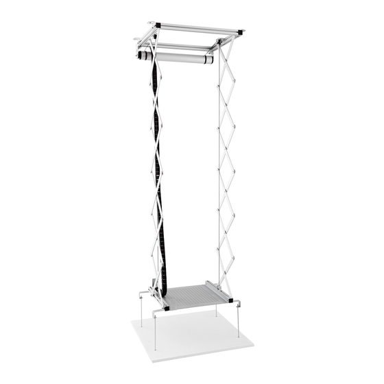
- Page 11 General description of the projector lift The following drawing provides an overview of the main components of the lift: Left structural profile 30x30 (mm) Back structural profile Fix pulley 30x30 (mm) Ceiling mounting bracket 40x40x60 (mm) Motor roller tube Cable management Closing plug for system...
- Page 12 Dimensions Side view Rear view Power supply Fig: Lift retracted (mm) Side view Rear view Power supply Fig: Lift extended (mm)
-
Page 13: Technical Specifications
Technical specifications Dimensions ‘lift retracted’: 575 x 240 x 554 mm (WxHxD) Dimensions ‘lift extended’: 575 x 1964 x 554 mm (WxHxD) Max usable area - projector hanging: 410 x 450 mm (WxD) Max usable area - projector sitting: 350 x 450 mm (WxD) Max size area of projector fixing points: 320 x 350 mm (WxD) Max projector size:... -
Page 14: Installation
Installation Please check PRIOR to installation that you have received all the components listed below. In case one or more parts are missing, please contact your dealer from whom you purchased the product. 4 x L brackets for ceiling mounting 1 x wall mounted switch with 8 screws and 8 washers Installation and user guide... - Page 15 Installation Do not remove the transport safety protection until the ceiling lift has been mounted. The spacers ensure the required tension of the wire ropes. Ceiling Installation Attach the L brackets (A) to the frame profiles. Use the appropriate screws and washers.
- Page 16 Installation For a safe installation, it is recommended to position the L brackets similar as per the illustration. We assume in this manual that the installation is to a flat and horizontal ceiling. Please use a spirit level to ensure a horizontal installation.
-
Page 17: Electrical Connection
Installation Once the lift has been mounted on the ceiling, remove the transport safety protection. Electrical connection Wall switch Fixing screws Switch base Electric panel Switch face 1 Remove the up / down switch face by pulling it upwards. Please do not use any tools to avoid causing damage 2 If necessary, loosen the screws, turn the switch face and remove it from the electric panel of the switch... - Page 18 Electrical connection Select the power cable in accordance with power consumption of the lift. The cable should be protected against high temperatures, oils, sharp edges and being crushed by other components. The following illustration shows the electrical connection to the supplied wall switch. 1: Blue (Neutral) 3: Black (Live) 2: Brown (Live)
- Page 19 Setting up the stop positions You can adjust the stop position points with the allen key adjusting points to meet your requirements. Please carry out this step with the lift ONLY without the projector or ceiling tile attached. Upper Stop Position (when projector is in ceiling) PLEASE NOTE: The upper stop position comes supplied in its highest position and being moved higher could seriously damage the lift.
- Page 20 Installation of the projector When you mount the projector to the lift, the lift has to be completely extended. Attach the projector to the profiles using appropriate screws (not supplied). Please ensure that the projector is installed with the centre of gravity in the centre of the lift.
- Page 21 Installation of the ceiling tile First attach the four sliding brackets (D) to the lower right and left frame profiles of the ceiling lift. Use the hex head screws (I) and screw them into the nuts already on the frame profiles. Attach the threaded rods (E) to the mounting brackets using the nuts (F).
-
Page 22: Maintenance And Repair
Disposal The disposal of the components must be carried out in accordance with the laws of the country in which the ceiling lift has been installed. The EC directives must be observed: 91 / 156 / CEE waste 91 / 689 / CEE hazardous waste 94 / 62 / CE packaging and packaging waste Maintenance and repair The ceiling lift should be subject to a safety check every six months. - Page 23 Maintenance and repair Date Notes Month Year Positive result Negative result Signature Date Notes Month Year Positive result Negative result Signature...
- Page 24 Maintenance and repair Date Notes Month Year Positive result Negative result Signature Date Notes Month Year Positive result Negative result Signature...
Need help?
Do you have a question about the PL2000 and is the answer not in the manual?
Questions and answers