Advertisement
Quick Links
PTAC Duct Kits
Introduction
These kits allow the PTAC unit to supply conditioned air, not
only to the room where the unit is installed, but also to an
adjoining room.
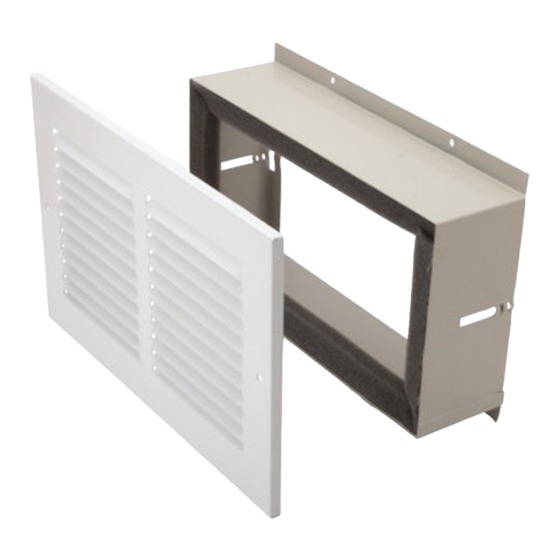
NOTE: In the Main Duct Kit, Extension Duct Kit and the
Terminal Duct Kit all required hardware is provided (not
shown in Figures 1, 2 and 3).
TRANSITION
Figure 1
Main Duct Kit - MDK02
Figure 2
Extension Duct Kit - EDK02
ATTENTION INSTALLING PERSONNEL
As a professional installer you have an obligation to
know the product better than the customer. This
includes all safety precautions and related items.
Prior to actual installation, thoroughly familiarize
yourself with this Instruction Manual. Pay special
attention to all safety warnings. Often during
installation or repair it is possible to place yourself
in a position which is more hazardous than when
the unit is in operation.
September 2000
Rev. 2
RECOGNIZE THIS SYMBOL AS A SAFETY PRECAUTION
Installation Instructions
Terminal Duct Kit - TDK02
5"
1/2"
BAFFLES
18-3/8"
3-1/4" MIN
FLOOR LINE
Installation Dimensions
Remember, it is your responsibility to install the
product safely and to know it well enough to be able
to instruct a customer in its safe use.
Safety is a matter of common sense...a matter of
thinking before acting. Most dealers have a list of
specific good safety practices...follow them.
The precautions listed in this Installation Manual
are intended as supplemental to existing practices.
However, if there is a direct conflict between existing
practices and the content of this manual, the
precautions listed here take precedence.
Made in USA
Figure 3
10"
END OF
INNER WALL
DUCT
CUT-OUT
EXTENSION
TRANSITION
1-3/8" MIN
(FOR DUCT KIT)
UNIT FRONT
WALL SLEEVE
OUTSIDE
WALL
2-3/4" MIN
(FOR SUBBASE KIT)
BOTTOM OF
WALL SLEEVE
SUBBASE KIT
7-1/2"
20-1/2"
Figure 4
1/4" MIN
11113402
Advertisement

Related Manuals for Amana TDK02


Summary of Contents for Amana TDK02
- Page 1 NOTE: In the Main Duct Kit, Extension Duct Kit and the Terminal Duct Kit all required hardware is provided (not shown in Figures 1, 2 and 3). Figure 3 Terminal Duct Kit - TDK02 10" END OF INNER WALL 5"...
- Page 2 WARNING Installation Disconnect power source before removing 1. If the cabinet front is screwed to the chassis then remove the screws located behind the inlet grille. Pull the chassis. the inlet grille forward from the top of the grille to access two screws (Figure 5).
- Page 3 Two mounting slots are provided in each bracket. To Grille Support Brackets mount extension on right side, adjust bracket so the screws are in left side of bracket slots; for mounting extension on the left, adjust brackets so the screws are in right side of slots.
- Page 4 Terminal Duct Kit (TDK02) Installation The sheet metal collar of the terminal duct kit must be mounted in the wall of the adjoining room opposite the room where the main duct kit is attached to the PTAC chassis. 1. Cut a hole in the wall of the adjoining room such that the hole is centered on the extension duct that is currently in the wall of the opposite room.